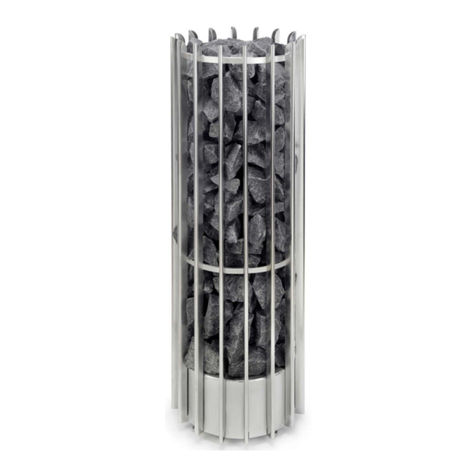
Norseman XPAS Guide

Special Notes
It is important to read this entire document and to keep it for future reference.
The following special notices highlight important information in the installation
and maintenance sections. Each serves a special purpose and is displayed
in the format shown:
This symbol indicates a potentially hazardous situation, which, if not
avoided, can result in personal injury or damage to the equipment.
This symbol indicates a potentially hazardous situation, which,
if not avoided, may be a shock hazard.
This symbol indicates an imminently hazardous situation, which,
if not avoided, could result in death or serious injury.
CAUTION
CAUTION
WARNING
Part No. M11882.Rev.6.01 August 2019 Printed in Canada
XPA Series
Explosion-Proof Panel Heater
Installation, Operation, & Maintenance Instructions

2
2
TABLE OF CONTENTS
A. Product Certification 2
B. Pre-Installation 3
C. Installation 3
C.1 General Requirements..........................................................................................3
C.2 Mounting Bracket Installation: XPA & XPAS Heaters.............................................4
C.3 Mounting Bracket Installation: XPAR Heaters .......................................................4
D. Wiring 6
D.1 General.................................................................................................................6
D.2 Wire Guard (optional)............................................................................................6
E. Start-up 6
F. Maintenance 7
G. Repairs 7
H. Troubleshooting 7

33
Product Certication / Pre-installation / Installation
A. PRODUCT CERTIFICATION
Depending on the particular model ordered, the heater is suitable
for the following areas:
• CSA C/US Certied for Class I, Div 1, Groups A, B, C, D or
Groups C, D, CSA Type 4; Temp. Code T2 (215°C) T2D, T3,
T3B, T3C or T4
• ATEX II 2G Ex d IIC or IIB, T2 (215°C), T3 or T4, GbIP66
• IECEx Ex d IIC or IIB, T2 (215°C), T3 or T4, Gb, IP66
NOTE: - Standard XPA Models: -50°C to +40°C
- High Ambient XPA Models: -50°C to +55°C or 60°C
depending on model. CSA Only
B. PRE-INSTALLATION
1. Initially, inspect the heater for possible damage due to
shipping and handling. Claims for shipping damages shall
be placed with the carrier.
2. Check the heater nameplate to ensure that the heater area
classication and temperature code are suitable for the
hazardous area classication. For details of hazardous
locations with potential for explosion, refer to the
Canadian Electrical Code or National Electrical Code.
3. Check to ensure that the heater voltage is the same as the
supply voltage.
4. The heater must be installed by qualied personnel in strict
compliance with national and local electrical codes.
WARNING
WARNING. Do not connect the heater to an electrical
supply voltage other than that shown on the
productnameplate.
Figure 1 – Model XPAL/XPAS convection heater
Figure 2 – Model XPAL/XPAS convection heater
Figure 3 – Model XPAR convection heater
C. INSTALLATION
C.1 General Requirements
1. The XPA heater is intended for industrial use and is to
be mounted in an enclosure. The main function of this
heater is to prevent the damaging effects of moisture and
condensation on the components inside the enclosure. It
is not intended for comfort heating use.
2. XPAL and XPAS heaters are approved for enclosure
mounting either horizontally or side mounted with the
junction box at the side. XPAR heaters are approved for
vertical mounting only with the junction box at the bottom.
Ensure that the enclosure is sufciently strong to support
the heater which, depending on the model, could weigh
up to 15 lbs (7 kg).
3. Do not recess the XPA heater into the wall. Use the
bracket supplied with the unit to ensure that the minimum
spacing from the wall of 1" (25 mm) is maintained.
4. If more than one heater is being installed, maintain at least
3" (76 mm) between adjacent heater extrusions.
5. The XPA heater relies on natural convection and “black
heat” radiation to transfer heat to the surroundings. See
Table 1, page4 for minimum clearances above heater.

4
4
Installation
Table 1 – Minimum clearance above heater
T-Code
XPAS XPAL
Side Mount
XPAL
Horizontal
XPAR
Vertical
in mm in mm in mm in mm
T4 6152 6152 6152 6152
T3C/T3B 6152 6152 9229 6152
T3 12 305 9229 12 305 9229
T2D 15 381 12 305 18 457 12 305
6. Maintain a 3" (76 mm) clearance and NEVER LESS THAN 1"
(25 mm) clearance in front of and at the sides of the heater.
7. The XPAL and XPAS heater relies on vertical convective
ow through its ns to operate properly. The unit must
be mounted in the horizontal or side mount orientation,
as applicable. Under no circumstance can the heater be
mounted vertically on its end with the junction box on
the top or bottom and the at n surfaces in a horizontal
position. The XPAR heater must be mounted vertically with
the junction box at the bottom. Refer to Figure 11– Figure
13, page5 for allowable mounting orientations.
CAUTION
CAUTION. The heater’s surface is hot when the heater
is energized. Keep all combustibles away from the
heater and maintain the recommended installation
clearances at all times.
C.2 Mounting Bracket Installation: XPAL & XPAS Heaters
Install heater with the supplied hardware in accordance with
the gures and instructions below (Figure 14 and Figure 15,
page6).
Step 1: Scribe lines into the mounting surface signifying the top
and side of the mounting bracket, indicating where the
mounting bracket will be located after installation (Figure 4
and Figure 5, page4)
Figure 4 – Scribe the top of the mounting bracket
Figure 5 – Scribe the side of the mounting bracket
Step 2: Remove the mounting bracket from the heater and install
it to the mounting surface, aligning the bracket with the
scribe marks from Step 1 (Figure 6, page4)
Figure 6 – Install the mounting bracket
Step 3: Secure the heater to the bracket by tightening the
provided Socket Head Cap Screws into the threaded
holes on each end of the heater (Figure 7, page4).
Figure 7 – Attach mounting bracket to heater itself
C.3 Mounting Bracket Installation: XPAR Heaters
Step 1: Scribe a mark into the mounting surface indicating where
the top part of the mounting bracket will be located after
installation (Figure 5, page4).
Figure 8 – Scribe the drop of the mounting bracket
Step 2: Measure down 0.625” (16 mm) from the scribed mark
and scribe a mark for the top bolt location. Measure an
additional 5.5” (140 mm) from the top bolt location to
indicate the bottom bolt location (Figure 9, page4).
Drill holes at the marked locations for the mounting bolts.
Figure 9 – Measure and scribe the top and bottom hole
locations and drill holes

55
Installation
Step 3: Pre-install the mounting bolts onto the mounting surface
allowing enough clearance to slide the mounting bracket
under the head of the supplied bolts. Position the heater
onto the mounting bolts and tighten securely (Figure 10,
page5).
Figure 10 – Position heater onto mounting bolts
NOTE: Proper use of supplied mounting bracket will
ensure minimum distance of 1” (25 mm) from the
mountingsurface.
Figure 11 – XPAL and XPAS heater mounting orientations
(horizontal only)
Figure 12 – XPAL and XPAS heater mounting orientations
(horizontal and side mount
Figure 13 – XPAR heater mounting orientations (vertical only)
Figure 14 – XPAL and XPAS heater basic mounting drawing
Figure 15 – XPAR heater basic mounting drawing
CAUTION
CAUTION. Never install one heater above the other.
To ensure safe operation, heater must be installed as
shown in Figure 11– Figure 13, page5). Installation
with ns in the incorrect orientation may result in an
unsafe condition (refer to Table 2, page6)
WARNING
WARNING. Improper orientation of the heater can
affect the safe and reliable operation of the heater.
YES NO NO
NO
YES YES
YES NO
Mounting bracket (included)
Hex bolts (included)
1/4-20UNC x 3/4" LG
Socket head
cap screws (included)
1/4-20 UNC x 1/2"
Protection grill
(optional)
3.31"
(84.1 mm)
Ø3/4 NPT threaded
conn. (typ.)
2.294"
(58.3 mm)
3/4" NPT THREADED
CONN. (TYP.)
MOUNTING BRACKET
SLIDE MOUNT ONTO
PANEL MOUNTED BOLTS
PROTECTION GRILL
(OPTIONAL)
5.50”
(139.7 mm)
0.625”
(15.9 mm)
7.00”
(178 mm)
0.625"
(15.9 mm)
5.50" (139.7 mm)
Mounting bracket slide mount
onto panel mounted bolts
Protection grill
(optional)
3/4" NPT
threaded conn.
(typ.)
2.294"
(58.3 mm)

6
6
Installation
Table 2 – Mounting orientation (Standard XPA Models)
Length Wattage Fig. No. Class I, Div 1& 2, see notes for Groups Weight Part No.
T2/T2D T3 T3B/T3C T4 lbs (kg)
4.375”
(111 mm)
75 12
7.4 (3.4)
XPAS-075
100 12 –XPAS-100
125 12 –XPAS-125
150 12 – – XPAS-150
200 12 – – XPAS-200
250 12 – – – XPAS-250
9”
(229 mm)
100 13
12.8 (5.9)
X PA L-10 0
150 13 X PA L-15 0
200 13 X PA L- 20 0
250 13 Horizontal Only X PA L- 25 0
300 13 –X P A L- 3 0 0
400 13 Horizontal Only –X PA L- 4 0 0
500 13 – – XPAL-500
600 13 Horizontal Only – – X PA L- 6 0 0
700 13 Horizontal Only – – – X PA L-7 0 0
7”
(178 mm)
50 14 Vertical Only Vertical Only Vertical Only Vertical Only
3.8 (1.7)
XPAR-050
80 14 Vertical Only Vertical Only Vertical Only –XPAR-080
125 14 Vertical Only Vertical Only – – XPAR-125
150 14 Vertical Only – – – XPAR-150
Table 3 – High Ambient XPA Models
Length Wattage Fig. No. Temperature Code Part No.
T2D(1) T3 T3A T3C
4.375”
(111 mm)
75 12 XPASH-075
100 12 n/a XPASH-10 0
125 12 n/a XPASH-125
150 12 n/a n/a n/a XPASH-150
200 12 n/a n/a n/a XPASH-200
9”
(229 mm)
100 13 XPALH-100
150 13 XPALH-150
200 13 XPALH-200
250 13 Horizontal Only XPALH-250
300 13 n/a XPALH-300
400 13 Horizontal Only Horizontal Only n/a XPALH-400
500 13 n/a n/a n/a XPALH-500
600 13 Horizontal Only n/a n/a n/a XPALH-600
7”
(178 mm)
50 14 Vertical Vertical Vertical Vertical XPARH-050
80 14 Vertical Vertical Vertical n/a XPARH-080
125 14 Vertical n/a n/a n/a XPARH-125
NOTE: 1. T2D models are rated for 55°C maximum ambient temperature.
2. All other heaters are rated for 60°C maximum ambient temperature.
3. High ambient units only available with XJB-4 junction box.
NOTE: Groups A, B, C & D, IIC apply when XJB-4 and XTWA junction boxes.
Groups C & D, IIB apply when using XT-311 and XT-411 junction boxes with adjustable thermostats.

77
Wiring / Start-Up
D. WIRING
D.1 General
1. Whenever hazardous materials are present, ensure that
the junction box covers are secure before energizing the
heater. Follow all applicable national and local codes
for hazardous location installation. The XPA heater is
available with a terminal housing. A terminal housing
may be required by national and/or local codes for
hazardouslocations.
2. Use supply wires suitable for 221°F (105°C) for standard
units or 257°F (125°C) for hight ambient units.
3. The connecting supply wires shall be installed to provide
for permanent wiring and have adequate protection
against mechanical damage.
4. Use approved conduit and conduit seals as required by
the national and local codes for hazardous locations.
5. To provide maximum protection, each XPA heater should
be fused individually using HRC fuses.
6. All heaters come factory prewired ready for direct
connection to power supply leads (see Figure 16,
page7).
6.1 Connect the power leads to terminals marked L1
and N or L2.
6.2 Connect the ground wire to the ground connection
located in the heater junction box cover.
7. Replace junction box cover securely. Do not
over-tighten.
8. For Cable Only XPA Units, heaters must be installed to
an unisulated grounded metal surface with the mounting
bracket supplied. Please refer to national and/or local
electrical codes for proper grounding installation in
hazardous locations.
Figure 16 – Wiring diagram for XPA convection heater
WARNING
WARNING. Whenever hazardous materials are present,
ensure that the terminal housing covers, plugs, etc,. are
secured (but not over-tightened) before energizing
theheater.
CAUTION
CAUTION. All circuits must be in the open position
before removing junction or terminal box covers.
CAUTION
CAUTION. Use supply wires suitable for 221°F (105°C)
or 257°F (125°C). Supply wires are to be fused
appropriately size HRCfusing.
WARNING
WARNING. Use approved conduit and conduit seals as
required by hazardous location standards.
CAUTION
CAUTION. Ensure that no power is connected to the
equipment prior to making any connections.
D.2 Wire Guard (optional)
Install wire guard by inserting wire arms into holes on heater ns.
E. START-UP
1. If the unit contains a junction box ensure the junction box
lid is securely installed onto the terminal housing.
2. Check to ensure that all plugs, screws, and covers are
securely in place.
3. Check associated electrical equipment.
4. Check that all wall mounting bracket connections are tight.
5. Turn on supply power.
6. If the unit is equipped with an adjustable thermostat, dial
the temperature required by twisting the thermostat knob.
WARNING
WARNING. To prevent unsafe operation of the heater
do not exceed the maximum allowable ambient
operating temperature of 104°F (40°C).
WARNING
WARNING. To prevent unsafe operation of the heater
do not exceed the maximum allowable ambient
operating temperature of 55°C or 60°C on high
ambient units.

8
8
Maintenance / Repair / Troubleshooting
Oakville
1-800-410-3131
1-905-829-4422
F 905-829-4430
Orillia
1-877-325-3473
1-705-325-3473
F 705-325-2106
WARRANTY:Under normal use the Company warrants to
the purchaser that defects in material or workmanship will be
repaired or replaced without charge for a period of 18 months
from date of shipment, or 12 months from the start date of
operation, whichever expires rst. Any claim for warranty must
be reported to the sales ofce where the product was purchased
for authorized repair or replacement within the terms of this
warranty.
Subject to State or Provincial law to the contrary, the Company
will not be responsible for any expense for installation, removal
from service, transportation, or damages of any type whatsoever,
including damages arising from lack of use, business interruptions,
or incidental or consequential damages.
The Company cannot anticipate or control the conditions of
product usage and therefore accepts no responsibility for
the safe application and suitability of its products when used
alone or in combination with other products. Tests for the
safe application and suitability of the products are the sole
responsibility of the user.
This warranty will be void if, in the judgment of the Company,
the damage, failure or defect is the result of:
• Vibration, radiation, erosion, corrosion, process
contamination, abnormal process conditions, temperature
and pressures, unusual surges or pulsation, fouling,
ordinary wear and tear, lack of maintenance, incorrectly
applied utilities such as voltage, air, gas, water, and others
or any combination of the aforementioned causes not
specically allowed for in the design conditions or,
• Any act or omission by the Purchaser, its agents, servants
or independent contractors which for greater certainty, but
not so as to limit the generality of the foregoing, includes
physical, chemical or mechanical abuse, accident,
improper installation of the product, improper storage
and handling of the product, improper application or the
misalignment of parts.
No warranty applies to paint nishes except for manufacturing defects
apparent within 30 days from the date of installation.
The Company neither assumes nor authorizes any person to assume for it
any other obligation or liability in connection with the product(s).
The Purchaser agrees that all warranty work required after the initial
commissioning of the product will be provided only if the Company
has been paid by the Purchaser in full accordance with the terms and
conditions of the contract.
The Purchaser agrees that the Company makes no warranty or
guarantee, express, implied or statutory, (including any warranty of
merchantability or warranty of tness for a particular purpose) written
or oral, of the Article or incidental labour, except as is expressed or
contained in the agreement herein.
LIABILITY: Technical data contained in the catalog or on the
website is subject to change without notice. The Company reserves
the right to make dimensional and other design changes as required.
The Purchaser acknowledges the Company shall not be obligated
to modify those articles manufactured before the formulation of the
changes in design or improvements of the products by the Company.
The Company shall not be liable to compensate or indemnify the
Purchaser, end user or any other party against any actions, claims,
liabilities, injury, loss, loss of use, loss of business, damages, indirect
or consequential damages, demands, penalties, nes, expenses
(including legal expenses), costs, obligations and causes of action of
any kind arising wholly or partly from negligence or omission of the
user or the misuse, incorrect application, unsafe application, incorrect
storage and handling, incorrect installation, lack of maintenance,
improper maintenance or improper operation of products furnished
by the Company.
Edmonton
1-780-466-3178
F 780-468-5904
5918 Roper Road
Alberta, Canada T6B 3E1
Houston
1-800-654-2583
1-713-433-2600
F 713-433-4541
Denver
1-855-244-3128
1-303-979-7339
F 303-979-7350
For further assistance, please call 24hr hotline: 1.800.661.8529 (U.S.A. and Canada)
Please have model and serial numbers available before calling.
PLEASE ADHERE TO INSTRUCTIONS IN THIS MANUAL
Failure to do so may be dangerous and may void certain provisions of
your warranty.
F. MAINTENANCE
Check the following before every heating season:
WARNING
WARNING. Disconnect power from the heater before
performing any maintenance. Failure to do so can result
in property damage, injury, or death.
WARNING
WARNING. Painted and anodized surfaces have a
potential risk of electrostatic discharge. Do not use a
dry cloth to clean this device, use only a damp cloth.
G. REPAIRS
H. TROUBLESHOOTING
WARNING
WARNING. Only open the junction box if it is safe to
doso!
These heaters contain a thermal fuse. If the unit is not operating
within proper constraints, the unit may have overheated, causing
the thermal fuse to open. Check the thermal fuse by disconnecting
the power, opening the junction box and measuring the resistance
across the terminals. If the resistance is innite, the fuse has been
triggered and the unit must be sent to Thermon Heating Systems,
for repair.
1. Remove junction box cover and inspect the electrical
connections. Ensure the connections are tight and wires
are not burned or frayed.
2. Inspect the heater and its surroundings. Make sure that
heater clearances are maintained and no debris is around
the heater or stuck in the ns.
3. Check all mounting hardware and ensure fasteners
aretight.
4. Replace the cover securely and turn on the
power supply.
1. If the heater malfunctions, and is no longer operating,
send the heater to the factory for servicing. Do not attempt
to service the unit.
2. When returning the heater you can ll out the online
repair form at:
http://www.ccithermal.com/online-repair-form.php
Or, include the following information with the heater
whenshipping:
– Company name and address
– Contact name
– Telephone/fax number/email
– Product model and serial numbers
– Tagging codes
– Advise if an estimate is required prior to starting
the repair
– P.O. Number
– Description of problem(s) and/or require repairs
– Special instructions (if applicable)
– Return shipping instructions
NOTE: If your circuit contains a thermostat and the ambient
temperature is high enough to turn off the thermostat,
the measured resistance will be innite, this test will
not check the thermal fuse.

Oakville
1-800-410-3131
1-905-829-4422
F 905-829-4430
Orillia
1-877-325-3473
1-705-325-3473
F 705-325-2106
WARRANTY:Under normal use the Company warrants to
the purchaser that defects in material or workmanship will be
repaired or replaced without charge for a period of 18 months
from date of shipment, or 12 months from the start date of
operation, whichever expires rst. Any claim for warranty must
be reported to the sales ofce where the product was purchased
for authorized repair or replacement within the terms of this
warranty.
Subject to State or Provincial law to the contrary, the Company
will not be responsible for any expense for installation, removal
from service, transportation, or damages of any type whatsoever,
including damages arising from lack of use, business interruptions,
or incidental or consequential damages.
The Company cannot anticipate or control the conditions of
product usage and therefore accepts no responsibility for
the safe application and suitability of its products when used
alone or in combination with other products. Tests for the
safe application and suitability of the products are the sole
responsibility of the user.
This warranty will be void if, in the judgment of the Company,
the damage, failure or defect is the result of:
• Vibration, radiation, erosion, corrosion, process
contamination, abnormal process conditions, temperature
and pressures, unusual surges or pulsation, fouling,
ordinary wear and tear, lack of maintenance, incorrectly
applied utilities such as voltage, air, gas, water, and others
or any combination of the aforementioned causes not
specically allowed for in the design conditions or,
• Any act or omission by the Purchaser, its agents, servants
or independent contractors which for greater certainty, but
not so as to limit the generality of the foregoing, includes
physical, chemical or mechanical abuse, accident,
improper installation of the product, improper storage
and handling of the product, improper application or the
misalignment of parts.
No warranty applies to paint nishes except for manufacturing defects
apparent within 30 days from the date of installation.
The Company neither assumes nor authorizes any person to assume for it
any other obligation or liability in connection with the product(s).
The Purchaser agrees that all warranty work required after the initial
commissioning of the product will be provided only if the Company
has been paid by the Purchaser in full accordance with the terms and
conditions of the contract.
The Purchaser agrees that the Company makes no warranty or
guarantee, express, implied or statutory, (including any warranty of
merchantability or warranty of tness for a particular purpose) written
or oral, of the Article or incidental labour, except as is expressed or
contained in the agreement herein.
LIABILITY: Technical data contained in the catalog or on the
website is subject to change without notice. The Company reserves
the right to make dimensional and other design changes as required.
The Purchaser acknowledges the Company shall not be obligated
to modify those articles manufactured before the formulation of the
changes in design or improvements of the products by the Company.
The Company shall not be liable to compensate or indemnify the
Purchaser, end user or any other party against any actions, claims,
liabilities, injury, loss, loss of use, loss of business, damages, indirect
or consequential damages, demands, penalties, nes, expenses
(including legal expenses), costs, obligations and causes of action of
any kind arising wholly or partly from negligence or omission of the
user or the misuse, incorrect application, unsafe application, incorrect
storage and handling, incorrect installation, lack of maintenance,
improper maintenance or improper operation of products furnished
by the Company.
Edmonton
1-780-466-3178
F 780-468-5904
5918 Roper Road
Alberta, Canada T6B 3E1
Houston
1-800-654-2583
1-713-433-2600
F 713-433-4541
Denver
1-855-244-3128
1-303-979-7339
F 303-979-7350
For further assistance, please call 24hr hotline: 1.800.661.8529 (U.S.A. and Canada)
Please have model and serial numbers available before calling.
PLEASE ADHERE TO INSTRUCTIONS IN THIS MANUAL
Failure to do so may be dangerous and may void certain provisions of
your warranty.

Avertissements particuliers
Les avertissements particuliers précisés dans les sections
suivantes relatives à l’installation et à l’entretien visent à fournir des
renseignements importants. Chacun répond à une situation particulière
et est illustré comme suit:
Ce symbole indique une situation potentiellement dangereuse
pouvant provoquer des blessures corporelles ou des
dommages à l’appareil dans l’éventualité où celle-ci ne
pourrait être évitée.
Ce symbole indique une situation potentiellement dangereuse
pouvant présenter un danger d’électrocution dans
l’éventualité où celle-ci ne pourrait être évitée.
Ce symbole indique une situation potentiellement dangereuse
pouvant provoquer une mort ou des blessures graves dans
l’éventualité où celle-ci ne pourrait être évitée.
ATTENTION
AVERTISSEMENT
ATTENTION
N° de pièce M11882.Rev.6.01 Date de publication: août 2019 Imprimé au Canada
Série XPA
Radiateurs muraux antidéagration
Instructions d’installation, d’utilisation et d’entretien
MC

1111
Certications du produit
A. Certifications du produit 10
B. Avant l’installation 11
C. Installation 11
C.1 Exigences générales ..........................................................................................11
C.2 Installation du support de montage: Radiateurs XPAL et XPAS..........................12
C.3 Installation du support de montage: Radiaeurs XPAR ........................................12
D. Câblage 14
D.1 Général...............................................................................................................14
D.2 Grillage de protection (en option)........................................................................14
E. Mise en marche 14
F. Entretien 15
G. Réparations 15
H. Dépannage 15
TABLE DES MATIÈRES

12
12
Avant l’installation / Installation
B. AVANT L’INSTALLATION
1. Inspecter d’abord le radiateur an de repérer d’éventuels
dommages causés par le transport et la manutention. Les
réclamations pour les dommages causés par le transport
doivent être déposées auprès du transporteur.
2. Vérier la plaque signalétique du radiateur an de conrmer
que la classication de zone et le code de température
du radiateur sont adaptés à la classication de la zone
dangereuse. Pour obtenir plus de renseignements
relativement aux emplacements présentant des dangers
potentiels de déagration, se reporter au Code canadien
de l’électricité ou au Code national de l’électricité.
3. Vérier que le voltage requis par le radiateur correspond à
la tension d’alimentation.
4. Le radiateur doit être installé par un personnel qualié se
conformant strictement aux codes nationaux et locaux de
l’électricité.
AVERTISSEMENT
AVERTISSEMENT. Ne pas brancher le radiateur
dans une alimentation électrique d’une tension autre
que celle indiquée sur la plaque signalétique
duproduit.
Figure 1 – Radiateur à convection des séries XPAL/XPAS
Figure 2 – Radiateur à convection des séries XPAL/XPAS
Figure 3 – Radiateur à convection de série XPAR
A. CERTIFICATIONS DU PRODUIT
Selon le modèle particulier commandé, le radiateur est approprié
pour les zones suivantes:
• Certié CSA C/US pour la Classe I, Division 1, Groupes A, B, C,
D ou Groupes C, D, CSA Type 4; code de température T2 (215
°C) T2D, T3, T3B, T3C ou T4
• ATEX II 2G Ex d IIC ou IIB, T2 (215 °C), T3 ou T4, Gb, IP66
• IECEx Ex d IIC ou IIB, T2 (215 °C), T3 ou T4, Gb, IP66

1313
Installation
C. INSTALLATION
C.1 Exigences générales
1. Le radiateur XPA est destiné à un usage industriel et doit
être installé dans une enceinte. La fonction principale
de ce radiateur est de prévenir les effets néfastes de
l’humidité et de la condensation sur les composants qui se
trouvent à l’intérieur de l’enceinte. Il n’a pas été conçu pour
être utilisé comme appareil de chauffage de confort.
2. Les radiateurs XPAL et XPAS sont approuvés pour un
montage sur la cloison d’une enceinte, horizontalement
ou sur le côté,avec la boîte de jonction sur le côté (voir
le Tableau 2, page14). Les radiateurs XPAR sont
approuvés pour un montage vertical uniquement avec
la boîte de jonction en bas. Conrmer que la cloison
de l’enceinte est sufsamment solide pour soutenir le
radiateur dont le poids, selon le modèle, peut atteindre
15lb (7 kg).
3. Ne pas encastrer le radiateur XPA dans le mur. Utiliser le
support fourni avec l’appareil pour respecter l’espacement
minimal requis à partir du mur de 1 po (25 mm).
4. Si plus d’un radiateur est installé, respecter une distance
d’éloignement minimale de 3 po (76 mm) entre les pièces
extrudées des radiateurs adjacents.
5. Le radiateur XPA utilise la convection naturelle et le
rayonnement thermique sans émission de lumière pour
le transfert de la chaleur dans son environnement. Voir
le Tableau 1, page13 pour connaître les distances
minimales au-dessus du radiateur.
Tableau 1 – Distance minimale au-dessus du radiateur
Code T
XPAS
XPAL
Montage sur
le côté
XPAL
Horizontal
XPAR
Vertical
po mm po mm po mm po mm
T4 6152 6152 6152 6152
T3C/T3B 6152 6152 9229 6152
T3 12 305 9229 12 305 9229
T2D 15 381 12 305 18 457 12 305
6. Maintenir un espacement de 3 po (76 mm) et JAMAIS
MOINS DE 1 po (25 mm) à l’avant et sur les côtés du
radiateur.
7. Les radiateurs XPAL et XPAS nécessitent un ux convectif
vertical à travers les ailettes pour fonctionner correctement.
L’appareil doit être monté à l’horizontale ou sur le côté,
selon le cas. Le radiateur ne doit en aucun cas être monté
verticalement sur son extrémité avec la boîte de jonction
en haut ou en bas et les surfaces planes des ailettes
dans une position horizontale. Le radiateur XPAR doit être
monté verticalement avec la boîte de jonction en bas. Voir
les gures 11, 12 et 13 pour connaître les orientations de
montage admissibles.
ATTENTION
ATTENTION. La surface du radiateur est chaude
lorsque le radiateur est sous tension. S’assurer de
conserver tout combustible loin du radiateur et
respecter les distances de dégagement
recommandées en tout temps.

14
14
Installation
C.2 Installation du support de montage: Radiateurs XPAL et
XPAS
Installer le radiateur à l’aide de la quincaillerie fournie conformément
aux gures et aux instructions ci-dessous (Figure 14 et Figure 15,
page15).
Étape 1: Faire des lignes sur la surface de montage de façon à
indiquer l’emplacement du haut et des côtés du support
de montage après l’installation (Figure 4 et Figure 5,
page14).
Figure 4 – Marquage du haut du support de montage
Figure 5 – Marquage du côté du support de montage
Étape 2: Retirer le support de montage du radiateur et l’installer
sur la surface de montage, en alignant le support avec
les marques faites à l’étape 1 (Figure 6, page14).
Figure 6 – Installation du support de montage.
Étape 3: Fixer le radiateur au support en serrant les vis
hexagonales à tête creuse fournies dans les trous
letés situés à chaque extrémité du radiateur (Figure 7,
page14).
Figure 7 – Fixation du support de montage au radiateur lui-
même.
C.3 Installation du support de montage: Radiaeurs XPAR
Étape 1: Faire une marque dans la surface de montage indiquant
l’endroit où la partie supérieure du support de montage
sera située après l’installation (Figure 8, page14).
Figure 8 – Marquage de l’emplacement de la partie supérieure
du support de montage.
Étape 2: Faire une marque 0,625 po (16 mm) sous la marque faite
précédemment pour l’emplacement du boulon supérieur.
Faire une marque 5,5 po (140 mm) sous l’emplacement
du boulon supérieur pour indiquer l’emplacement du
boulon inférieur (Figure 9, page14). Percer des trous
aux emplacements marqués pour les boulons de xation.
Figure 9 – Mesure et marquage des emplacements de xation
supérieurs et inférieurs et forage des trous.
Étape 3: Préinstaller les boulons de montage sur la surface de
montage en laissant un dégagement sufsant pour faire
glisser le support de montage sous la tête des boulons
fournis. Placer le radiateur sur les boulons de montage et
serrer fermement (Figure 10, page14).
Figure 10 – Mise en place du radiateur sur les boulons de
montage.
Remarque: Une bonne utilisation du support de montage fourni assurera le
respect de la distance minimum de 1 po (25 mm) par rapport à la
surface de montage.

1515
Installation
ATTENTION
ATTENTION. Ne jamais installer un radiateur au-dessus
d’un autre radiateur. An d’assurer un fonctionnement
sécuritaire, le radiateur doit être installé comme illustré
dans les gures 11, 12 et 13. Une installation où les
ailettes ne sont pas dans la bonne orientation pourrait
causer une situation dangereuse (voir le tableau 2).
AVERTISSEMENT
AVERTISSEMENT. Une mauvaise orientation du
radiateur pourrait réduire la sécurité et la abilité du
fonctionnement du radiateur.
OUI NON NON
Figure 11 – Orientations de montage des radiateurs XPAL et XPAS – à
l’horizontale seulement.
NON
OUI OUI
Figure 12 – Orientations de montage des radiateurs XPAL et XPAS – à
l’horizontale et sur le côté.
OUI NON
Figure 13 – Orientation de montage du radiateur XPAR – à la verticale
seulement.
Support de montage
(incluses)
Boulons à tête
hexagonale (inclus)
Vis hexagonales à tête
creuse (incluses)
¼-20UNC x ½ po LG
Grille de
protection
(en option)
3.31"
(84.1 mm)
Ø3/4 Connecteur
leté NPT (typ.)
Figure 14 – Schéma de montage de base des radiateurs XPAL et XPAS.
2.294"
(58.3 mm)
3/4" NPT THREADED
CONN. (TYP.)
MOUNTING BRACKET
SLIDE MOUNT ONTO
PANEL MOUNTED BOLTS
PROTECTION GRILL
(OPTIONAL)
5.50”
(139.7 mm)
0.625”
(15.9 mm)
7.00”
(178 mm)
0.625"
(15.9 mm)
5.50" (139.7 mm)
Support de xation coulissant sur les
boulons montés sur la cloison
Grille de protection
(en option)
3/4" Connecteur
leté NPT (typ.)
2.294"
(58.3 mm)
Figure 15 – Schéma de montage de base du radiateur XPAR
Remarque: Pour les dimensions du radiateur, qui sont propres à la conguration
de votre radiateur, voir les schémas d’homologation applicables
disponibles sur le site Web à l’adresse www.norsemanheaters.com
ou auprès de votre représentant du service à la clientèle.

16
16
Installation
Tableau 2 - Orientation de montage (Modèles XPA Standard)
La
Longueur Les Watts Le Numéro
Du Tableau
Class I, Div 1& 2, les remarques pour les groupes Le Poids Le Numéro
De La Pièce
T2/T2D T3 T3B/T3C T4 lbs (kg)
4.375”
(111 mm)
75 12
7.4 (3.4)
XPAS-075
100 12 –XPAS-100
125 12 –XPAS-125
150 12 – – XPAS-150
200 12 – – XPAS-200
250 12 – – – XPAS-250
9”
(229 mm)
100 13
12.8 (5.9)
X PA L-10 0
150 13 X PA L-15 0
200 13 X PA L- 20 0
250 13 Horizontal Seulement X PA L- 25 0
300 13 –X P A L- 3 0 0
400 13 Horizontal Seulement –X PA L- 4 0 0
500 13 – – XPAL-500
600 13 Horizontal Seulement – – X PA L- 6 0 0
700 13 Horizontal Seulement – – – X PA L-7 0 0
7”
(178 mm)
50 14 Vertical Seulement Vertical Seulement Vertical Seulement Vertical Seulement
3.8 (1.7)
XPAR-050
80 14 Vertical Seulement Vertical Seulement Vertical Seulement –XPAR-080
125 14 Vertical Seulement Vertical Seulement – – XPAR-125
150 14 Vertical Seulement – – – XPAR-150
Tableau 3 - Les modèles XPA à température Ambiante Élevée
Remarque: Pour les groupes A, B, C et D : IIC s’applique lorsque les boîtes de jonction XJB-4 et XTWA sont employées.
La Longueur Les Watts Le Numéro
Du Tableau
Code De Température Le Numéro De
La Pièce
T2D(1) T3 T3A T3C
4.375”
(111 mm)
75 12 XPASH-075
100 12 n/a XPASH-100
125 12 n/a XPASH-125
150 12 n/a n/a n/a XPASH-150
200 12 n/a n/a n/a XPASH-200
9”
(229 mm)
100 13 XPALH-100
150 13 XPALH-150
200 13 XPALH-200
250 13 Horizontal Seulement XPALH-250
300 13 n/a XPALH-300
400 13 Horizontal Seulement Horizontal Seulement n/a XPALH-400
500 13 n/a n/a n/a XPALH-500
600 13 Horizontal Seulement n/a n/a n/a XPALH-600
7”
(178 mm)
50 14 Vertical Seulement Vertical Seulement Vertical Seulement Vertical Seulement XPARH-050
80 14 Vertical Seulement Vertical Seulement Vertical Seulement n/a XPARH-080
125 14 Vertical Seulement n/a n/a n/a XPARH-125
Remarque: 1. Les modèles T2D sont évalués pour une température ambiante maximale de 55C.
Pour les groupes C et D : IIB s’applique lorsque les boîtes de jonction avec thermostats XT-311 et XT-411 sont employées.
2. Tous les autres chauffages sont évalués pour une température ambiante de 60C.
3. Les unites à haute température ambiante ne sont que disponibles avec les boîtes de jonction XJB-4.

1717
Câblage / Mise en marche
D. CÂBLAGE
D.1 Général
1. Lorsque des matières dangereuses sont présentes,
veiller à ce que les couvercles de la boîte de jonction
soient bien en place avant de mettre le radiateur sous
tension. Suivre tous les codes nationaux et locaux
applicables pour l’installation dans un emplacement
dangereux. Le radiateur XPA est offert avec un boîtier
terminal. Un boîtier terminal peut être exigé par les codes
nationaux et/ou locaux pour les endroits dangereux.
2. Utiliser des câbles d’alimentation conçus pour une
température de 221°F (105°C) ou 257°F (125°C) for haute
ambiante.
3. Les câbles d’alimentation doivent être installés pour
assurer un câblage permanent et une protection adéquate
contre les dommages mécaniques.
4. Utiliser des conduits et des joints d’étanchéité de conduit
homologués et conformes aux codes nationaux ou locaux
en matière d’emplacements dangereux.
5. Pour assurer une protection maximale, chaque radiateur
XPA devrait avoir son propre fusible HPC.
6. Tous les radiateurs sont précâblés en usine et prêts pour
une connexion directe aux câbles d’alimentation (voir la
Figure 16, page17).
6.1 (Connecter les câbles d’alimentation aux bornes
marquées L1 et N ou L2.
6.2 Brancher le câble de mise à la terre à la prise de
terre située dans le couvercle de la boîte de jonction
du radiateur.
7. Bien remettre le couvercle de la boîte de jonction en place.
Ne pas trop serrer.
8. Pour les appareils XPA avec câble nu, les radiateurs
doivent être installés sur une surface métallique non
isolée et mise à la terre avec le support de montage
fourni. Voir les codes électriques nationaux et/ou locaux
pour l’installation d’une mise à la terre adéquate dans les
endroits dangereux.
Figure 16 – Schéma de câblage – Radiateur à convection XPA
AVERTISSEMENT
AVERTISSEMENT. Lorsque des matières
dangereuses sont présentes, veiller à ce que les
couvercles du boîtier abritant les bornes, les ches,
etc., soient bien en place (sans être trop serrés)
avant de mettre le radiateur sous tension.
ATTENTION
ATTENTION. Tous les circuits doivent être ouverts
avant de retirer les couvercles de la boîte de jonction
ou du caisson de borne.
ATTENTION
ATTENTION. Utiliser des câbles d’alimentation
conçus pour une température de 221°F (105°C) ou
257°F (125°C). Les câbles d’alimentation doivent être
raccordés à un fusible HPC de calibre adéquat.
AVERTISSEMENT
AVERTISSEMENT. Utiliser des conduits et des joints
d’étanchéité de conduit homologués conformes aux
emplacements dangereux.
D.2 Grillage de protection (en option)
Installer un grillage de protection en insérant les pattes du grillage
dans les trous sur les ailettes du radiateur.
E. MISE EN MARCHE
1. Si l’appareil contient une boîte de jonction, conrmer que
le couvercle de la boîte de jonction est solidement installé
sur le boîtier abritant les bornes.
2. Vérier que les ches, les vis et les couvercles sont
solidement en place.
3. Vérier les équipements électriques connexes.
4. Vérier que tous les ancrages du support de xation au
mur sont bien serrés.
5. Mettre sous tension.
6. Si l’appareil est équipé d’un thermostat réglable, ajuster la
température requise en tournant le bouton du thermostat.
AVERTISSEMENT
AVERTISSEMENT. An d’éviter tout fonctionnement
non sécuritaire du radiateur, ne pas dépasser la
température ambiante de fonctionnement maximale
permise de 104°F (40°C).
La Longueur Les Watts Le Numéro
Du Tableau
Code De Température Le Numéro De
La Pièce
T2D(1) T3 T3A T3C
4.375”
(111 mm)
75 12 XPASH-075
100 12 n/a XPASH-100
125 12 n/a XPASH-125
150 12 n/a n/a n/a XPASH-150
200 12 n/a n/a n/a XPASH-200
9”
(229 mm)
100 13 XPALH-100
150 13 XPALH-150
200 13 XPALH-200
250 13 Horizontal Seulement XPALH-250
300 13 n/a XPALH-300
400 13 Horizontal Seulement Horizontal Seulement n/a XPALH-400
500 13 n/a n/a n/a XPALH-500
600 13 Horizontal Seulement n/a n/a n/a XPALH-600
7”
(178 mm)
50 14 Vertical Seulement Vertical Seulement Vertical Seulement Vertical Seulement XPARH-050
80 14 Vertical Seulement Vertical Seulement Vertical Seulement n/a XPARH-080
125 14 Vertical Seulement n/a n/a n/a XPARH-125
AVERTISSEMENT
ATTENTION. Assurez-vous qu’aucun courant
électrique est branché à l’équipement avant de faire
toutes connexions.
Charge de chauffage
N (120V unités)
L2 (208V & 240V
unités)
Thermostat
L1
AVERTISSEMENT
AVERTISSEMENT. An d’éviter tout fonctionnement
non sécuritaire du radiateur, ne pas dépasser la
température ambiante de fonctionnement maximale
permise de 55°C ou 60°C pour les appareils à
température ambiante élevée.

18
18
Entretrien / Réparations / Dépannage
F. ENTRETIEN
Vérier les éléments suivants avant chaque saison de chauffage:
AVERTISSEMENT
AVERTISSEMENT. Débrancher l’alimentation du
radiateur avant d’effectuer un entretien. Ne pas
respecter cette directive peut causer des dommages
matériels, des blessures ou provoquer lamort.
AVERTISSEMENT
AVERTISSEMENT. Les surfaces peintes et
anodisées présentent un risque potentiel de
décharge électrostatique. Ne pas utiliser un chiffon
sec pour nettoyer ce radiateur, utiliser uniquement
un chiffonhumide.
1. Retirer le couvercle de la boîte de jonction et inspecter
les connexions électriques. Conrmer que les connexions
sont serrées et que les câbles ne sont pas brûlés ou
eflochés.
2. Inspecter le radiateur et ses environs. Conrmer que les
distances de dégagement du radiateur sont respectées et
qu’aucun débris ne se trouve autour du radiateur ou n’est
collé aux ailettes.
3. Vérier tout le matériel de montage et conrmer que les
xations sont bien serrées.
4. Remettre le couvercle en place en le xant solidement et
mettre sous tension.
G. RÉPARATIONS
1. En cas de dysfonctionnement du radiateur et d’arrêt de
son fonctionnement, envoyer le radiateur à l’usine pour
une réparation. Ne pas tenter de réparer l’appareil.
2. Lors du retour du radiateur, veuillez remplir le formulaire de
réparation en ligne à l’adresse:
http://www.ccithermal.com/onlinerepair-form.php
Ou, inclure les informations suivantes avec le radiateur
lors de l’expédition:
– Nom et adresse de l’entreprise
– Personne-ressource
– Numéro de téléphone, numéro de télécopieur,
adresse courriel
– Numéros du modèle et de série du produit
– Codes de marquage
– Précisez si une estimation est nécessaire avant
d’effectuer la réparation
– Numéro du bon d’achat
– Description du ou des problèmes et/ou des
réparations requises
– Instructions particulières (le cas échéant)
– Instructions d’expédition pour le retour
H. DÉPANNAGE
AVERTISSEMENT
AVERTISSEMENT. Seulement ouvrir la boîte de
jonction s’il est sécuritaire de le faire!
Ces radiateurs contiennent un fusible thermique. Si l’appareil
ne fonctionne pas en respectant les contraintes appropriées,
il pourrait avoir surchauffé, provoquant l’ouverture du fusible
thermique. Vérier le fusible thermique en déconnectant
l’alimentation, en ouvrant la boîte de jonction et en mesurant la
résistance entre les bornes. Si la résistance est innie, le fusible
a été déclenché et l’appareil doit être envoyé à Thermon Heating
Systems pour réparation.
Remarque: Si votre circuit contient un thermostat et que la température
ambiante est sufsamment élevée pour éteindre le thermostat, la
résistance mesurée sera innie et ce test ne vériera pas le fusible
thermique.

NOTES

Pour obtenir une aide supplémentaire, veuillez appeler: 1-800-661-8529 (U.S.A. and Canada)
Merci de préparervos numéros de modèle et de série avante d’appeler.
MC
Oakville
1-800-410-3131
1-905-829-4422
F 905-829-4430
Orillia
1-877-325-3473
1-705-325-3473
F 705-325-2106
GARANTIE:Dans des conditions normales d’utilisation, la
Société garantit à l’acheteur que les produits ayant des défauts
matériels ou de fabrication seront réparés ou remplacés sans frais
pour une période de 18 mois à compter de la date d’expédition
ou 12 mois à partir de la date de début de fonctionnement, selon
la date qui arrive à expiration la première. Toute réclamation dans
le cadre de la garantie doit être adressée à l’agence commerciale
dans laquelle le produit a été acheté afin d’obtenir une réparation
ou un remplacement selon les termes de cette garantie.
Non obstant toute loi fédérale ou provinciale au contraire, la Société
ne pourra être tenue pour responsable des frais encourus pour
l’installation, le retrait du service, le transport ou les dommages de
quelque nature que ce soit, y compris les dommages résultant d’un
manque d’utilisation, d’interruptions d’activité ou de dommages
directs ou indirects.
La Sociéte ne peut anticiper ou contrôler les conditions
d’utilisation du produit et, par conséquent, décline toute
responsabilité quant à l’application et l’adaptation en toute
sécurité de ses produits lors de leur utilisation seuls ou
en combinaison avec d’autres produits. Il est de la seule
responsabilité de l’utilisateur d’effectuer des tests pour vérier
l’application et l’adaptation en toute sécurité des produits.
Cette garatie sera nulle si, à l’appréciation de la Socitété, le
dommage, la panne ou le défaut a été causé par:
• Des vibrations, des radiations, de l’érosion, de la corrosion,
une contamination du processus, des conditions opératiores
anormales, le températion et la pression, une poussée ou
une pulsation anormale, l’encrassement, une usure normale,
un manque d’entretien, des services appliqués de manière
inappropriée tels que le voltage, l’air, le gaz l’eau et autres, ou
toute autoriées par les conditions de régime; ou
• Tout acte omission de la part de l’Acheteur ses agents,
employés ou entrepreneur indépendant, comprenant pour
une plus grande précision, mais pas au point de limiter
la généralité de ce qui précède, une mauvaise utilisation
physique, chimique ou mécanique, un accident, une
mauvaise installation du produit, de mauvaises conditions
de stockage ou de manipulation du produit, une application
inappropriée ou en défaut d’alignment des pièces.
Aucune garantie ne s’applique à la nition de peinture, excepté dans le
cas de défauts de fabrication apparents dans les 30 jours à compter
de la date d’installation.
Le Société n’assume ni m’autorise auncune personne à assumer en son
nom toute autre obligation ou responsabilité en rapport avec
le/les produit(s).
L’Acheteur accepte que la Société ne fournisse aucune garantie,
expresse, implicite ou légale (y comprise toute garantie de qualité
marchande ou de convenance à des ns particulières), écrite ou
orale, du produit ou de la main-d’oeuvre indirecte, à l’exception des
dispositions exprimées ou contenues dans le présent accord.
RESPONSABILITÉ: Les données techniques contenues dans
le catalogue ou sur le site Web song sujettes à modication sans préavis.
La Société se réserve le droit d’apporter des modications par rapport
aux dimensions ou à la conception si nécessaire. L’Acheteur reconnaît
que la Société ne sera pas dans l’obligation de modifier ces articles
manufacturés avant la formulation des modifications de conception ou
des améliorations apportées aux produit par la Société
La Société ne sera pas tenue de dédomanger ou d’indemniser
l’Acheteur, l’utilisateur final ou toute autre partie pour les actions, les
réclamations les responsabilités, les préjudices les sinistres, la perte
d’usage, le perte d’activité, les dommages, les dommages indirects ou
consécutifs, les demands, les sanctions, les amendes, les dépanses
(y compris les dépenses légales), les pertes, les obligations et les
conséquences d’une action de quelque nature que ce soit découlant
entièrement ou en partie de la négligence ou de l’omission de l’utilisateur
ou de la mauvise utilisation, de la mauvaise application, de l’utilisation
dangereuse, de mauvaise installation, du manque d’entretien, du
mauvaise entretien ou de la mauvaise opération des produits fournis par
la Société.
Edmonton
1-780-466-3178
F 780-468-5904
5918 Roper Road
Alberta, Canada T6B 3E1
Denver
1-855-244-3128
1-303-979-7339
F 303-979-7350
Tout manquement à ces dernières pourrait s’avérer dangereux et
invalider certaines dispositions de votre garantie.
VEUILLEZ VOUS CONFORMER AUX INSTRUCTIONS
CONTENUES DANS CE MANUEL.
This manual suits for next models
3
Table of contents
Languages:
Other Norseman Heater manuals
