Barthelme 66000574 User manual

3. TECHNISCHE DATEN
Betriebsspannung: 10 bis 48 V DC
Schutzklasse: III
Ausgangsstrom: max. 2,2 A / Kanal
Maße (L|B|H): 180|52|22 mm
Eigen-Stromverbrauch (ohne LED):
ca. 5 bis 20 mA
Umgebungstemperatur:
0 °C bis max. +50 °C
(Betrieb nur in trockenen Innenräumen mit
ausreichender Luftzirkulation zur Wärme-
abfuhr, nicht betauend)
Schutzart: IP 20
Hersteller: Josef Barthelme GmbH & Co. KG
4. SICHERHEITSHINWEISE
Das Gerät erzeugt bei Betrieb Wärme. Auf
ausreichende Luftzirkulation muss geach-
tet werden. Das Gerät darf sich im Regelbe-
trieb bei max. Last nicht mehr als auf 80 °C
erwärmen.
Es ist unbedingt auf die richtige Polung der
Anschlüsse zu achten. Das Modul verfügt in-
tern über einen Verpolungsschutz, trotzdem
kann Verpolen (auch kurzzeitig) das Gerät
zerstören.
Beim nicht bestimmungsgemäßem Betrieb,
Verpolen, bei Umbau des Gerätes, bei Sach-
oder Personenschäden, die durch unsach-
gemäße Handhabung oder Nichtbeachten
der Sicherheitshinweise verursacht werden,
übernehmen wir keinerlei Haftung und der
Garantieanspruch erlischt vollständig.
Sofern sich die LEDs in Feuchtbereichen
(z.B. Schwimmbäder, Sauna, ...) befinden, ist
besonders auf die geltenden Vorschriften
bezüglich der Stromversorgung zu achten.
Die Installation des Produktes darf nur
durch eine qualifizierte Fachkraft erfolgen,
die mit den geltenden Vorschriften (z.B. DIN,
VDE, EN) vertraut ist.
Dieses Produkt ist kein Spielzeug und ge-
hört nicht in Kinderhände. LEDs können
sehr heiß werden! Es ist in jedem Fall rat-
sam, die vorgegebene Maximaltemperatur
der Leuchtmittel nicht zu überschreiten, da
sich dies nachhaltig auf Lebensdauer und
Lichtintensität der LEDs auswirken kann.
WARNUNG 1:
LEDs können eine sehr hohe Lichtintensität
entwickeln, selbst im gedimmten Zustand!
Speziell in Verbindung mit Optiken können
selbst schwache LEDs sehr gefährlich wer-
den. Der direkte Blick in LEDs kann irrepa-
rable Schäden an der Netzhaut des Auges
hervorrufen. Verwenden Sie Diusoren zur
Lichtstreuung.
WARNUNG 2:
Bitte beachten Sie, dass LED-Licht seine
Intensität sehr schnell wechseln kann.
Schnell wechselnde Lichteekte können
die Wahrnehmung beeinflussen, Beschwer-
den hervorrufen, oder Anfälle bei Personen
mit Neigung zu Epilepsie auslösen.
5. MONTAGE
Der elektrische Anschluss darf nur durch
eine Elektrofachkraft durchgeführt wer-
den, die mit den geltenden Richtlinien
vertraut ist!
Vorsicht: Schalten Sie die Stromversor-
gung bzw. die Anschlussleitung span-
nungsfrei, bevor Sie jegliche Arbeiten
vornehmen!
MONTAGEORT
Achten Sie darauf, dass das Produkt auf
einen stabilen, ebenen, kippfesten Unter-
grund montiert wird. Das Gerät erzeugt
beim Betrieb Wärme. Auf ausreichende
Luftzirkulation muss geachtet werden.
GEBRAUCHS-
ANLEITUNG
FÜR
CHROMOFLEX PRO
DALI STRIPE CV
4-KANAL
DALI-DT8-KOMPATIBEL
BITTE AUFMERKSAM LESEN UND
AUFBEWAHREN!
Art.-Nr. 66000574
1. EINFÜHRUNG
Der CHROMOFLEX Pro DALI Stripe CV (DALI
DT8) ist entwickelt worden, um spannungs-
gesteuerte LEDs auf bis zu 4-Ausgangs-
kanälen über DALI zu steuern. Die Anzahl
der verwendeten Ausgangskanäle und
auch die Art Dimmkurve kann einfach über
DIP-Schalter eingestellt werden.
2. BESTIMMUNGSGEMÄSSE
VERWENDUNG
Das Steuergerät ist für trockene Innenräume
konzipiert! Sollten sich dafür geeignete LEDs
im Außen- oder Feuchtbereich befinden, bie-
ten wir hierfür auch optionale Gehäuse an.
Das Steuergerät darf nur mit einer an die
LEDs angepassten Stromversorgung betrie-
ben werden. Andere Verbraucher als LEDs
(insbesondere induktive Verbraucher, wie
etwa Motoren, Trafos oder Drosseln) können
das Gerät zerstören.
Sollten diese zuvor genannten Punkte nicht
eingehalten werden, kann es zum Kurz-
schluss oder elektrischen Schlag kommen.
Der CHROMOFLEX Pro stripe CV, 4-Kanal
(DALI-DT8) wurde nach den geltenden Richt-
linien entwickelt. DALI (Digital Addressable
Lighting Interface) ist eine standardisierte
digitale Kommunikationsschnittstelle im Be-
reich der Gebäudeautomation.
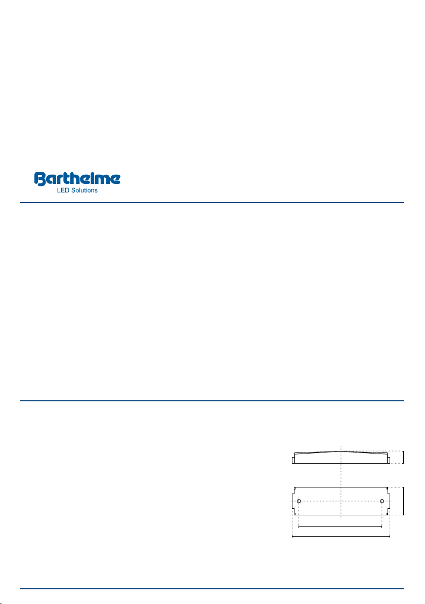
ABB.: 1
Abmessungen/Montagelöcher
2252
152,60
180
6. ANSCHLUSS
Bitte beachten Sie, dass die LEDs unbe-
dingt im stromlosen Zustand des Dim-
mers angeschlossen werden müssen.
HINWEISE ZUR WAHL DES NETZTEILES:
Wichtig: Das Netzteil muss über entspre-
chende Puls-Belastbarkeit verfügen. Un-
stabilisierte oder zu schwache Netzteile
können Flackern bei Farbübergängen
hervorrufen.
Wichtig: Die Spannungsversorgung muss
auf die verwendeten LEDs abgestimmt
sein! Eine ungeeignete Spannungsver-
sorgung kann zu Funktionsstörungen,
unerwünschtem Flackern, Zerstörung der
LEDs, Zerstörung der Elektronik oder im
schlimmsten Fall, zu Überhitzung führen.
Wir raten dringend von der Verwendung
unstabilisierter Billig-Netzteile ab! Auch
spezielle „LED-Netzteile“ sind meist unge-
eignet, da diese bereits Steuerungselekt-
ronik für Konstatstrom enthalten können,
welche nicht mit nachgeschalteten Steu-
ergeräten, wie etwa den CHROMOFLEX
Pro DALI stripe CV , 4-Kanal (DALI-DT8),
kompatibel sind.
Wir empfehlen in jedem Fall Spannungs-
versorgungen in Schaltnetzteil-Techno-
logie! Geeignete Netzteile sind bei uns
erhältlich.
Ein Netzteil kann natürlich auch mehrere
Module gleichzeitig speisen. In diesem Fall
ist auf ausreichende Leistung des Netz-
teils zu achten. Zur Verdrahtung können
Leitungen mit einem Querschnitt von ma-
ximal 2,5 mm² verwendet werden.
Die Module sollten mit mindestens 10
V DC versorgt werden, die maximal zu-
lässige Spannung beim CHROMOFLEX Pro
DALI stripe CV, 4-Kanal (DALI-DT8) beträgt
48 V DC.
6.1 CHROMOFLEX PRO DALI STRIPE CV,
4-KANAL (DALI-DT8)
„CV“ steht für „Constant Voltage“, also
Konstantspannung. Dieses Modell ver-
fügt über keine Strombegrenzung. Es
gibt die Versorgungsspannung direkt an
die LED-Streifen weiter. Wenn also der
LED-Streifen 24 V DC benötigt, muss dies
auch als Spannung durch das vorgeschal-
tete Netzteil bereitgestellt werden.
Hinweis: In der Praxis sind LED-Streifen
mit 12, 24 und 48 V DC üblich. LED-Strei-
fen können teilweise, je nach Länge, sehr
hohe Ströme benötigen.
Hinweis zu unseren LED-Streifen: Barthel-
me LED-Streifen werden meist auf Rollen
mit einer Länge von bis zu 6 Metern gelie-
fert. Der Stromverbrauch liegt dabei in der
24 V DC-Version bei 1,5 A, pro Farbe.
Beim CHROMOFLEX Pro DALI stripe
CV, 4-Kanal (DALI-DT8) beträgt der max.
Strom dabei beim 4-Kanal-Betrieb 2,2 A
pro Kanal. Hierbei ist unbedingt darauf zu
achten, dass alle Ausgänge miteinander
gebrückt werden!
ANMERKUNGEN/ERGÄNZUNGEN
Bei den Ausgangskanälen:
• Verpolung vermeiden
• auf korrekte Spannung achten
• sicherstellen, dass die Leistung je Aus-
gangskanal nicht überschritten wird
• keinesfalls stromgesteuerte LEDs (CC)
anschließen.
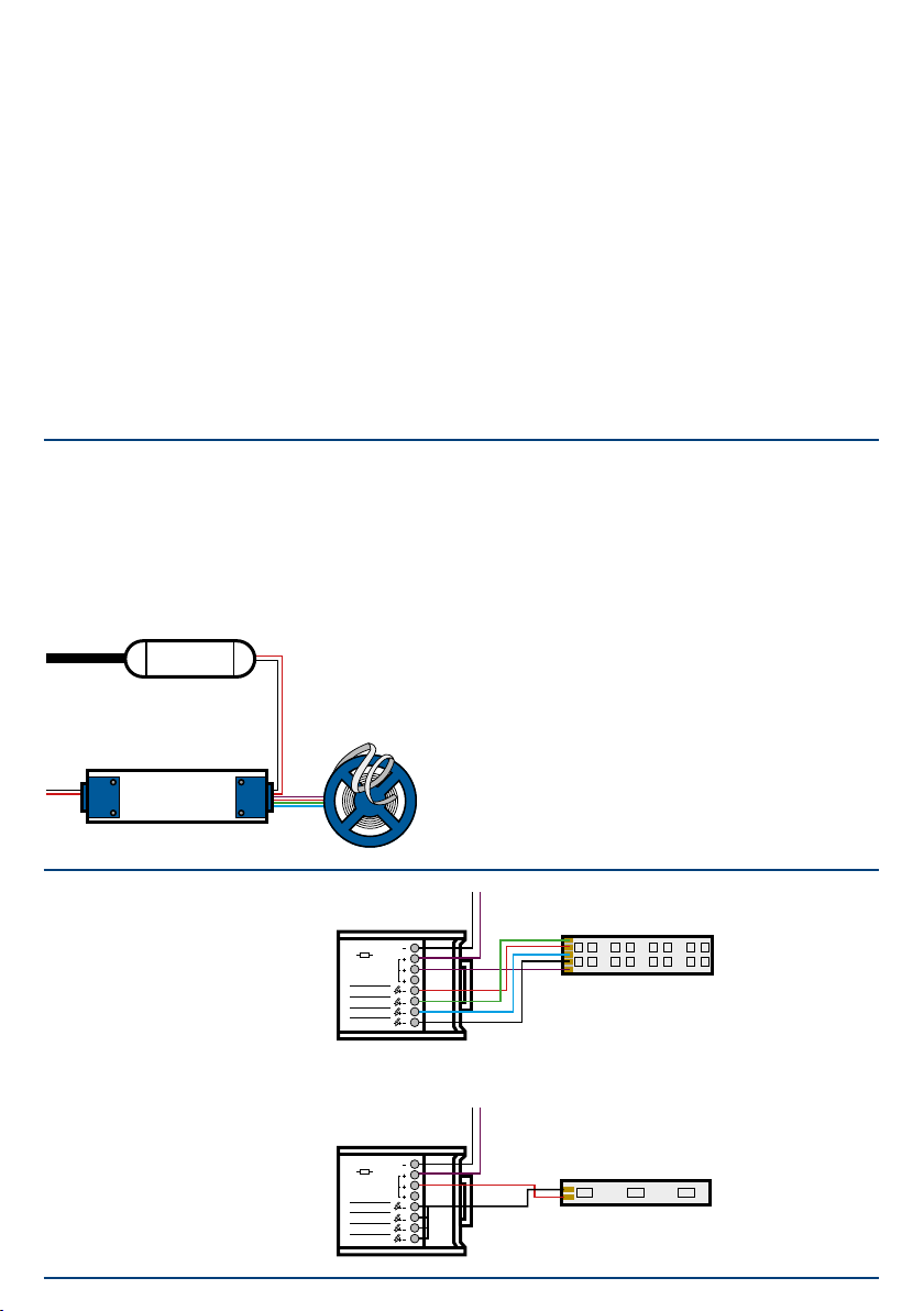
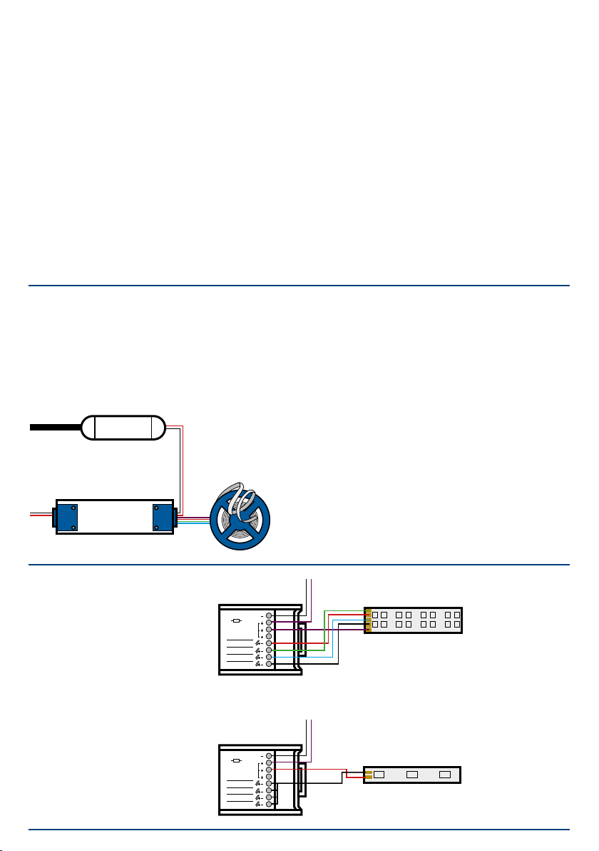
230 V AC
10 bis 48 V DC
DALI DT8
BUS
ABB.: 2
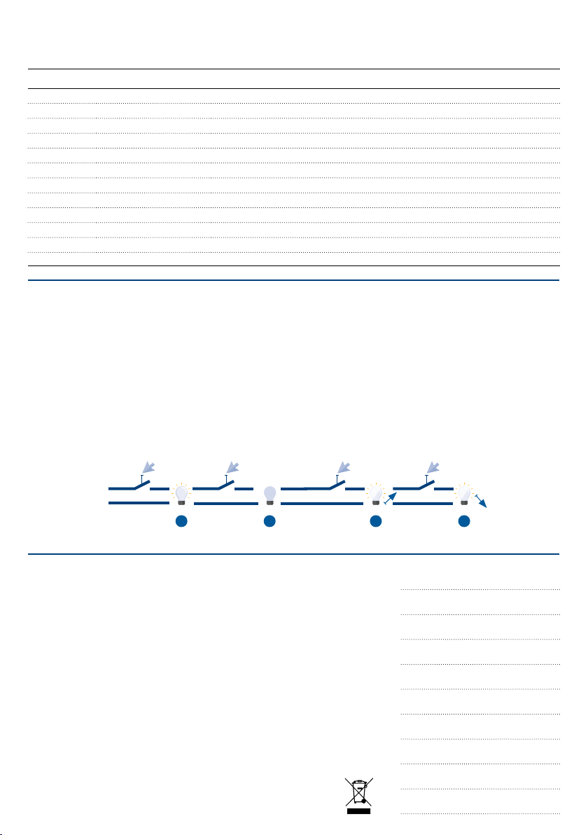
ABB.: 3
W/A
B
G
R
4
3
2
1
CH Imax. 4x2,2A
ta: 0-50°C
tc:80^C
10..48VDC PWR
IN
COM
max. 32A
W/A
B
G
R
4
3
2
1
CH Imax. 4x2,2A
ta: 0-50°C
tc:80^C
10..48VDC PWR
IN
COM
max. 32A
ABB.: 4

7. BETRIEB
Betreiben Sie das Produkt nur, wenn es
einwandfrei funktioniert. Im Fehlerfall
schalten Sie das Produkt sofort aus und
betreiben es erst wieder nach Überprü-
fung durch eine Elektrofachkraft. Dies ist
der Fall, wenn:
• sichtbare Beschädigungen auftreten
• das Produkt nicht einwandfrei arbeitet
• es qualmt, raucht, oder etwa bei hör-
baren Knistergeräuschen
• eine Überhitzung zu erkennen ist
Reparaturen des Produktes oder Arbeiten
an netzspannungsführenden Teilen dürfen
nur Fachkräfte des Elektrohandwerks vor-
nehmen.
WARNUNG: Hier besteht sonst Lebensge-
fahr durch elektrischen Schlag!
So vermeiden Sie Störungen und Brand-
gefahren:
•
Decken Sie das Produkt nicht ab. Beein-
trächtigen Sie nicht die Luftzirkulation.
•
Hängen und befestigen Sie nichts an dem
Produkt, insbesondere keine Dekoration.
•
Lassen Sie Kinder nicht unbeaufsichtigt
mit elektrischen Produkten spielen! Kin-
der können Gefahren im Umgang mit
elektrischer Energie nicht immer richtig
einschätzen.
•
Beim Einschalten und nach Fehlern wird
ein Softstart durchgeführt. Bei einem
Kurzschluss eines Ausgangs wird eine
Minute lang versucht, erneut zu schal-
ten. Sollte der Kurzschluss danach noch
vorhanden sein, muss der Dimmer neu
gestartet werden. Siehe Blinkmuster
„Fataler Fehler“.
•
Wenn das Netz getrennt wird, kann es
bei Kondensator-Netzteilen vorkommen,
dass der Controller noch einige Zeit mit
Spannung versorgt wird. Folglich erkennt
der Controller, dass ein Systemfehler vor-
liegt und schaltet die Kanäle auf 100 %.
7.1 ERSTE INBETRIEBNAHME
Schließen Sie die CHROMOFLEX Pro DALI
stripe CV, 4-Kanal (DALI-DT8)-Geräte gem.
den Abb. 2 und 3 an. Stellen Sie dabei
sicher, dass entsprechende LED-Streifen
und das richtige Netzteil an den CHRO-
MOFLEX Pro DALI stripe CV, 4-Kanal
(DALI-DT8) angeschlossenen sind. Nach
Anlegen der Versorgungsspannung sollte
das Modul auf allen Ausgängen die maxi-
male Helligkeit (100 %) einstellen.
Die Ausgangskanäle lassen sich über
DIP-Schalter bündeln (Kanal-Link).
Gebündelte Kanäle verhalten sich wie
ein einzelner Kanal, es wird nur eine
DALI-Kurzadresse verwendet. Eventuell
vorhandene Einstellungen (Werte, Szenen,
Gruppen) werden solange deaktiviert, bis
die Kanalbündelung aufgehoben wird.
DIP-SCHALTER BELEGUNG
1
Hier können die verschiedenen Kanal-
Optionen eingestellt werden:
- Kanal 1, 2, 3 und 4 separat
- Kanal 1 und 2 gebündelt sowie
3 und 4 gebündelt
- Kanal 1, 2, 3, und 4 gebündelt
- RGBW-Modus
- TUNABLE WHITE-Modus separat
- TUNABLE WHITE-Modus gebündelt
2
3
4
Nur im TUNABLE WHITE-Modus:
const. = hält den Farbübergang konstant
linear
max. = erzeugt die maximale Helligkeit
5Hier kann die PWM-Frequenz eingestellt
werden: 976Hz / 244Hz
6
Art der Farbkurve:
Definierbar,
auf Barthelme LED-Streifen bezogen
DIP
Blinkmuster / 4 s. Anmerkung
Modulstart INIT OOOOOOOOOO---------- Systemstart
Standby O------------------- Alle Ausgänge auf AUS
Ausgang eingeschaltet OOOOOOOOOOOOOOOOOOOO Min. ein Ausgang > 0
Empfang Bus-Ereignis O-O----------------- DALI-Telegramm empfangen
Betrieb über Tasteingang OOOO—OO------------- Taster am DALI-Eingang ist gedrückt,
Netzspannung liegt an
Programmiermodus OOOOO-----OOOOO----- DALI-Gerät wurde mit Initialize ausgewählt.
Fehler 1 O-O-O-O-O-O---O----- Abschaltung der Ausgänge wegen Überlast
Fehler 2 O-O-O-O-O-O---O-O--- Reduzierung Ausgangslevel wegen Überlast (Derating)
Fataler Fehler O-O-O-O-O-O-O-O-O-O- Shutdown wegen Überlast/Übertemperatur
STATUS-LED:
Auf dem Modul befindet sich eine Status-
LED. Nachfolgend die Bedeutung der
Blinkmuster:
KONTAKT
Josef Barthelme GmbH & Co. KG
Oedenberger Str. 149
90491 Nürnberg | Germany
T: +49 911 42 476 0
www.barthelme.de
TECHNISCHE ÄNDERUNGEN
VORBEHALTEN.
STAND 11|2023
NOTIZEN
7.2 DALI-BEFEHLE
Der Programmiermodus wird durch das
DALI-Kommando „Initialize“ gestartet.
DALI-Parameter Wertebereich Werkseinstellung
Power on-Level O,1 bis 100 % (0 bis 254) 100 %
Helligkeitswert nach dem Einschalten
System Failure-Level O,1 bis 100 % (0 bis 254) 100 %
Helligkeitswert bei DALI-Signalfehler
Min.-Level O,1 bis 100 % (0 bis 254) 0,1 %
kleinstmöglicher Helligkeitswert
Max.-Level O,1 bis 100 % (0 bis 254) 100 %
maximal erreichbarer Helligkeitswert
Fade Time von 0 bis 90,5 Sekunden < 0,7 s
Geschwindigkeit bei Änderung des Helligkeitswertes
Fade Rate von 1 bis 72 Schritten/s 45 Schritte/s
Schritte bei Änderungen des Hellig
keitswertes über DALI-Kommando dunkler/heller
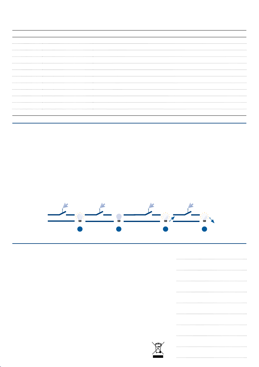
7.3 230 V AC-TASTEINGANG
Der DALI-Eingang kann als Tastein-
gang verwendet werden - dazu wird
eine Spannung von 230 V AC an den
DALI-Kontakt angeschlossen.
Mit der getasteten Phase können alle
Kanäle gemeinsam auf- und abgedimmt
werden. Es ist nicht möglich, die Kanäle
einzeln anzusteuern.
ABB.: 4
< 2 s < 2 s
230 V ACL
N
1 2
WICHTIG:
Bei der Verwendung des DALI-Eingangs
als reinen Tasteingang darf kein weite-
res DALI-Gerät oder DALI-Controller an-
geschlossen sein, da dann 230 V AC am
ganzen DALI-Strang anliegen.
> 2 s > 2 s
3 3
8. LIEFERUMFANG UND ZUBEHÖR
Jedes CHROMOFLEX Pro DALI stripe CV,
4-Kanal (DALI-DT8)-Modul wird mit die-
ser Anleitung geliefert. Sie ist Bestandteil
des Lieferumfangs für das Gerät und
muss dem Endverbraucher ausgehän-
digt werden.
WICHTIG:
Sämtliche CHROMOFLEX-Gebrauchsanlei-
tungen stehen Ihnen als Download unter
www.barthelme.de zur Verfügung.
Bitte informieren Sie sich vor der Ver-
wendung von Gebrauchsanleitungen
über evtl. Aktualisierungen.
3. TECHNICAL DATA VERSION CV
(EXCERPT)
Operating voltage: 10 V to 48 V DC
Protection class: III
Output current:
max. 2.2A / channel
Dimensions (L|W| H): 180 | 52 | 22 mm
Current consumption (without LED):
approx. 5 - 20 mA
Ambient temperature: 0°C - max. +50°C
(operation in dry conditions only with
sucient air circulation for heat dissipati-
on, non-condensing)
IP Protection: IP20
Manufacturer:
Josef Barthelme GmbH & Co. KG
4. SAFETY INSTRUCTIONS
The device generates heat during opera-
tion. Care must be taken to ensure ade-
quate air circulation. The device must not
exceed 80°C when operating at max. load.
It is important to pay attention to the
correct polarity of the connections. The
module includes internal reverse-pola-
rity protection; nevertheless, reverse po-
larity (even for a short time) can destroy
the device.
We assume no liability in the case of im-
proper operation, reverse polarity, modi-
fication of the device, property damage
or personal injury caused by improper
handling or non-observance of the safety
instructions – all of the above will invali-
date the warranty without exception.
If the LEDs are placed in a wet area (e.g.
swimming pools, saunas, etc.), particular
attention must be paid to the applicable
regulations regarding the power supply.
The product may only be installed by a
qualified specialist who is familiar with
the applicable regulations (e.g. DIN, VDE,
EN).
This product is not a toy and must be kept
out of the reach of children. LEDs can
also become very hot! It is always advisa-
ble not to exceed the specified maximum
temperature of the light sources, as this
can have a lasting eect on the life and
light intensity of the LEDs.
WARNING 1:
LEDs can develop a very high light inten-
sity, even when dimmed! Even weak LEDs
can become very dangerous, especially
when combined with optics. Looking di-
rectly into LEDs can cause irreparable
damage to the retina of the eye. Use dif-
fusers to scatter the light.
WARNING 2:
Please note that LED light can change its
intensity very quickly. Rapidly changing
lighting eects can aect perception and
cause discomfort or even seizures in in-
dividuals prone to epilepsy.
5. INSTALLATION
The electrical connection may only be
carried out by a qualified electrician who
is familiar with the applicable directives!
Caution: Turn o the power supply or the
connection lead before doing any works
INSTALLATION LOCATION
Make sure that the unit is mounted on a
stable, level, non-tilting base. In operation
the unit might produce heat. Care must
be taken to provide unrestricted air ven-
tilation.
1. INTRODUCTION
The CHROMOFLEX Pro DALI Stripe CV (DALI
DT8) has been developed to operate volta-
ge-controlled LEDs on up to 4 output chan-
nels via DALI.
The number of output channels used and
also the type of dimming curve can be ea-
sily set via DIP switches.
2. INTENDED USE
The control unit is intended for use in dry
indoor areas! If the LEDs are to be placed in
outdoor or wet areas, we also oer optional
housings for this purpose.
The control unit must only be operated
using a power supply that is suitable for the
LEDs. Devices other than LEDs (especially
inductive loads, such as motors, transfor-
mers or chokes) can destroy the controller.
Failure to comply with these points may re-
sult in short circuits or electric shocks.
The CHROMOFLEX Pro stripe CV, 4-channel
(DALI-DT8) was developed in accordance
with the applicable guidelines. DALI (Digital
Addressable Lighting Interface) is a stan-
dardised digital communication interface in
the field of building automation.
2252
152,60
180
OPERATING
INSTRUCTIONS
FOR
CHROMOFLEX PRO
DALI STRIPE CV
4-CHANNEL
DALI DT8 COMPATIBLE
PLEASE READ THIS MANUAL CARE-
FULLY AND KEEP IT IN A SAVE PLACE!!
Item-No. 66000574
FIG.: 1
Dimensions/Mounting holes
6. CONNECTION
Please note that the LEDs must only
be connected when the dimmer is in a
de-energised state.
NOTES ON THE CHOICE OF POWER SUP-
PLY:
Important: the power supply must also
have an adequate pulse load. Power sup-
plies that are non-stabilised or produce
too little power may cause flickering du-
ring colour transitions.
Important: the power supply must be
matched to the respective LEDs! An
unsuitable power supply may cause mal-
functions, unwanted flickering, destruc-
tion of the LEDs, destruction of the elec-
tronics, or in the worst case, overheating.
We strongly advise against the use of
non-stabilised, low-cost power supplies!
Furthermore, specialised „LED“ power
supplies are often unsuitable as they
may contain control electronics for cons-
tant current that are incompatible with
downstream controllers (such as the
CHROMOFLEX Pro).
In all cases, we recommend using power
supplies that are based on switched-mode
technology! We can supply suitable power
supplies.
Of course, one power supply can also feed
several modules simultaneously. In this
case, ensure the power supply generates
sucient power. For wiring, cables with a
maximum cross section of 2.5 mm² can
be used.
The modules should be supplied with at
least 10 V DC, the maximum permissible
voltage for the CHROMOFLEX Pro DALI
stripe CV, 4-channel (DALI-DT8) is 48 V DC.
6.1 CHROMOFLEX PRO DALI STRIPE CV
4-CHANNEL (DALI-DT8)
„CV“ stands for „Constant Voltage“. This
model has no current limit. It passes the
supply voltage directly to the LED strips.
Therefore, if the LED strip requires 24 V DC,
this must also be provided as voltage via
the upstream power supply.
Note: in practice, LED strips with 12 volts,
24 V DC and 48 V DC are common. LED
strips may sometimes require very high
currents, depending on their length.
Note about our LED strips: our LED strips
are usually supplied in rolls with an aver-
age length of about 6 metres; their pow-
er consumption is approx.1.5 amps at 24
volts per colour. For the model „CHRO-
MOFLEX Pro DALI DT8 CV“ the max. cur-
rent for a 4-channel system is 2.2 amps
per channel. If using only one channel (Fig.
4), 8.8 amps can be used. In this case, it
is important to ensure that all outputs are
bridged!
ADDITIONAL NOTES
At the output channels please
• avoid reverse polarity
• ensure the correct voltage
• ensure that the power per output chan-
nel is not exceeded
• never connect current-controlled
LEDs (CC).
FIG.: 3
W/A
B
G
R
4
3
2
1
CH Imax. 4x2,2A
ta: 0-50°C
tc:80^C
10..48VDC PWR
IN
COM
max. 32A
W/A
B
G
R
4
3
2
1
CH Imax. 4x2,2A
ta: 0-50°C
tc:80^C
10..48VDC PWR
IN
COM
max. 32A
FIG.: 4
FIG.: 2
230 V AC
10 to 48 V DC
DALI DT8
BUS

7.1 INITIAL COMMISSIONING
Connect the CHROMOFLEX Pro DALI stripe
CV, 4-Channel (DALI-DT8)devices as shown
in Fig. 2 and 3. Make sure that only suita-
ble LED strips and a compatible power
supply are connected to the CHROMOFLEX
Pro DALI stripe CV, 4-Channel (DALI-DT8).
When the supply voltage is connected,
the module should default to maximum
brightness (100 %) on all outputs.
The output channels can be „bundled“
via DIP switches (channel link). Bundled
channels behave like a single channel –
only one DALI short address is used. Any
existing settings (values, scenes, groups)
are deactivated until channel bundling is
cancelled.
How to avoid malfunctions or fire risk:
• Do not cover the product. Do not restrict
the air circulation.
• Do not hang or attach anything to the pro-
duct, in particular any form of decoration.
•
Do not let children play with electrical pro-
ducts while unsupervised! Children are
generally unaware of the hazards associ-
ated with electrical energy.
•
A soft start is performed when the device
is switched on or after a fault.
If an output is shorted, further switching
attempts will be made for 1 minute. If the
short circuit is still present after this time,
the dimmer must be restarted see „Fatal
Error“ flashing pattern.
7. OPERATION
Ensure the product is in perfect working
condition before using it. In the event of a
fault, switch o the product immediately
and do not operate it again until it has been
checked by a qualified electrician.
This is the case, if:
• there is visible damage to the device
• the product does not work properly
• the device emits smoke or audible
crackling noises
• signs of overheating are detected
Repairs to the product or work on live
parts may only be carried out by qualified
electricians.
WARNING: FAILURE TO FOLLOW THESE
INSTRUCTIONS MAY RESULT IN DANGER
TO LIFE DUE TO ELECTRIC SHOCK!
•
If a power supply with capacitors is used,
the controller may continue to receive po-
wer for some time after the mains power
is disconnected. Consequently, the control-
ler will detect that there is a system error
and switch the channels to 100 %.
DIP SWITCH ASSIGNMENT:
1
You can set the dierent channel-link
options here:
- Channel 1, 2, 3 and 4 are all separate
- Channel 1 and 2 are bundled,
channel 3 and 4 are bundled
- Channel 1, 2, 3, and 4 are bundled
- R, G, B, W mode
- TUNABLE WHITE mode separate
- TUNABLE WHITE mode bundled
2
3
4
Only in TUNABLE WHITE mode:
const = keeps the colour transition constant
and linear / max = produces the maximum
brightness
5You can set the PWM frequency here:
976 Hz / 244 Hz
6Type of colour curve:
Definable, based on Barthelme strips
DIP
Flashing pattern 4 sec. Note
Module start INIT OOOOOOOOOO---------- System start
Standby O------------------- All outputs OFF
Output switched on OOOOOOOOOOOOOOOOOOOO Min. one output > 0
Reception bus event O-O----------------- DALI telegram received
Operation via
push-button input OOOO—OO------------- Push-button on DALI-input is pushed, mains voltage is applied
Programming mode OOOOO-----OOOOO----- DALI device was selected with Initialize
Error 1 O-O-O-O-O-O---O----- Switching o outputs because of overload
Error 2 O-O-O-O-O-O---O-O--- Reducing output level because of overload (Derating)
Fatal error O-O-O-O-O-O-O-O-O-O- Shutdown because of overload/overtemperature
STATUS-LED:
On the device you can find a status LED.
The meanings of the patterns:
NOTES
7.3 230 V AC PUSH BUTTON INPUT
The DALI input can be used as a push
button input – for this, a voltage of 230 V
AC is connected to the DALI contact.
All channels can be opened and dimmed
together via the button-controlled phase.
It is not possible to control the channels
individually.
IMPORTANT:
When using the DALI input as a pure
push button input, no additional DALI
devices or DALI controllers may be
connected, as 230 V AC would then be
applied to the entire DALI line.
7.2 DALI COMMANDS
Programming mode is started with the
DALI command „Initialize“.
DALI Parameter Value range setting
Power On Level O,1 – 100 % (0 – 254) 100 %
Brightness after switching on
System Failure Level O,1 – 100 % (0 – 254) 100 %
Brightness at DALI signal error
Min. Level O,1 – 100 % (0 – 254) 0,1 %
min. brightness value
Max. Level O,1 – 100 % (0 – 254) 100 %
max. brightness value
Fade Time from 0 – 90,5 seconds < 0,7 s
Speed when changing brightness values
Fade Rate from 1 – 72 steps 45 steps
Steps when changing the brightness
value via DALI command darker/brighter
>2s >2s
3 3
FIG.: 5
<2s <2s
230V ACL
N
1 2
8. SCOPE OF DELIVERY
AND ACCESSORIES
Every CHROMOFLEX Pro DALI stripe CV,
4-Channel (DALI-DT8) unit is shipped with
this manual. It is part of the scope of de-
livery for the device and must be supplied
to the end user.
IMPORTANT NOTE:
All manuals for any CHROMOFLEX can be
downloaded at www.barthelme.de.
Please inform yourself about possib-
le updates prior to using the operating
instructions.
CONTACT
Josef Barthelme GmbH & Co. KG
Oedenberger Str. 149
90491 Nuremberg | Germany
T: +49 911 42 476 0
www.barthelme.de
SUBJECT TO TECHNICAL
CHANGES.
VERSION 11|2023
Table of contents
Languages:
Other Barthelme Lighting Equipment manuals


