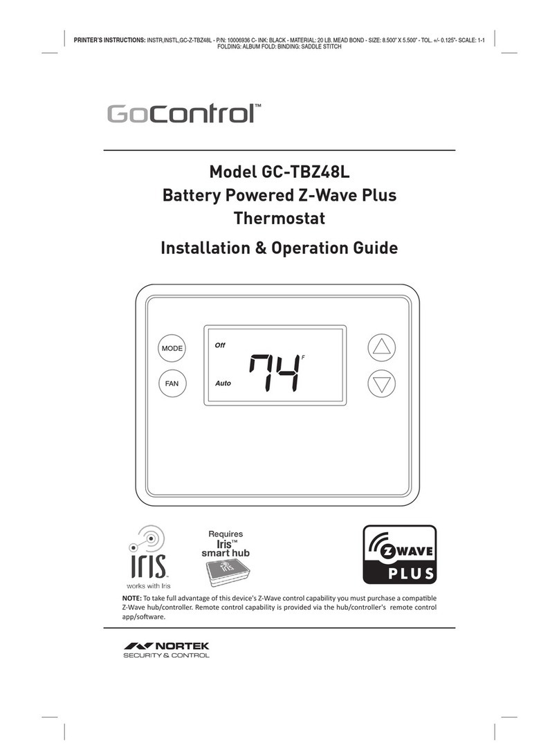
Nortek Security & Control 2GIG Z-Wave Plus 2GIG-STZ-1 User manual

PRINTER’S INSTRUCTIONS: INSTRUCTIONS, USER GUIDE, 2GIG-STZ-1 - P/N: 10028238 Rev-C
INK: BLACK; PANTONE 3005 C - MATERIAL: 60 LB. MEAD BOND - SIZE: 8.500” X 5.500” - TOL. +/- 0.125”- SCALE: 1-1 - FOLDING: ALBUM FOLD: BINDING: SADDLE STITCH
7
2
S
E
T
7
0
Fan
Au
t
o
C
o
ol
F
4
7%
User Guide
2GIG®Security & Automation System
2GIG Z-Wave Plus™ Battery Powered Thermostat

Copyright ©2020 Nortek Security & Control 1
2GIG-STZ-1
BATTERY POWERED THERMOSTAT
INSTALLATION INSTRUCTIONS
The 2GIG-STZ-1 Thermostat is a programmable, Z-Wave communicang thermostat. It can
be powered using 24VAC (if both “R”&”C”wires are available at the thermostat) or using
four (4) AA baeries. Using Z-Wave technology, you have the ability to use most compable
Z-Wave hubs/controllers to operate the thermostat, congure programming sengs as well
as displaying current condions in the home or oce.
Figure 1. Z-Wave Thermostat Front View
BATTERIES (4) PHILLIPS SCREWS (2)ANCHORS (2)
2GIG-STZ-1 THERMOSTAT
Fan On
41%
Heat
67 F
SET 70
Table of Contents
Typical Wiring for Standard Gas/Electric HVAC System....................................2
Typical Wiring for Heat Pump HVAC System ............................................3
Thermostat Power .................................................................4
The C Wire ....................................................................................4
24VAC Power .................................................................................4
Baery Power .................................................................................4
Z-Wave Operaon when Baery-Powered ..........................................................4
Remove Exisng Thermostat.........................................................5
Wiring Colors .................................................................................5
Install the Back Panel...............................................................6
Standard HVAC System Connecons. . . . . . . . . . . . . . . . . . . . . . . . . . . . . . . . . . . . . . . . . . . . . . . . . . . 7
Single and Dual Transformer Systems (Split Systems) .................................................7
Single Transformer System ..................................................................7
Dual Transformer Systems ...................................................................8
Heat Pump HVAC System Connecons ................................................9
Mount the Thermostat ............................................................10
Baery Installaon ...............................................................10
Thermostat Setup Menus ..........................................................11
Preset HVAC System sengs ....................................................................11
Wait Mode ..................................................................................11
Minimum Run Time (MRT) .....................................................................11
Frost Protecon ..............................................................................11
Entering Menu Mode .........................................................................12
Menu Mode Navigaon ....................................................................12
Setup Menu .................................................................................13
System Menu ................................................................................13
HUMI ......................................................................................13
Z-WAVE .....................................................................................13
CLOCK ......................................................................................13
INFO .......................................................................................13
Z-Wave Setup ................................................................................14
Removing from a Z-Wave Network ...............................................................15
SmartStart ...................................................................................15
Clock Menu ..................................................................................16
Seng the Clock ..............................................................................16
INFO Menu ..................................................................................16
Factory Reset ................................................................................16
Advanced System Sengs Menu ................................................................17
Thermostat Operaon .............................................................19
Main Thermostat Screen .......................................................................19
Backlight and Buon Operaon .................................................................19
Display ......................................................................................19
Staging Indicators .............................................................................19
Seng the System Mode .......................................................................20
System Modes ...........................................................................20
Special Heat Pump Mode: Emergency Heat ....................................................20
Seng the Heang or Cooling Temperature Setpoint. . . . . . . . . . . . . . . . . . . . . . . . . . . . . . . . . . . . . . . . . . . . . . . .21
Automac Setpoint Push ...................................................................21
Frost Protecon ..........................................................................21
Seng the Fan Mode ..........................................................................22
Fan Modes ..............................................................................22
User Customizaon ...........................................................................23
User preference sengs. ...................................................................23
Error Display .................................................................................24
AC and Baery Both Applied ................................................................24
Specicaons ....................................................................25
Z-Wave Informaon ...............................................................26
Advanced Z-Wave® Information .....................................................26
Support for Associaon Groups .................................................................26
Low Voltage Alarm ............................................................................26
Z-Wave Indicator. . . . . . . . . . . . . . . . . . . . . . . . . . . . . . . . . . . . . . . . . . . . . . . . . . . . . . . . . . . . . . . . . . . . . . . . . . . . . .26
Basic CC and Thermostat Mode CC ...............................................................26
Energy Saving Mode ..............................................................26
Scheduling ......................................................................26
Supported Command Classes and Security ............................................27
Regulatory Informaon ............................................................28
Industry Canada Noces ...........................................................28
Limited Warranty .................................................................29
What is Covered? .............................................................................29
How do I Obtain Warranty Service? ..............................................................29
Limitaons ..................................................................................29
Features Include
• Heang and cooling setup display opons
• System mode (OFF, Heat, Cool, Auto,
E-Heat)
• Fan mode control and display (Auto, ON)
• Changeover type for Heat Pump (HP)
systems
• On-screen setup of HVAC type, Fan type
• External humidier / dehumidier support
• Fahrenheit/Celsius mode and sensor
calibraon
Compatible with 24 VAC gas, oil, or electric
heating and air conditioning systems; or gas
millivolt heating systems
DO NOT USE ON 120VAC SYSTEMS!
Standard Systems
• 1 Stage Heang and Cooling
• 2 Stage Heang and Cooling
Heat Pump Systems
• 1 Stage Heang and Cooling
• 2 Stage Heang and Cooling
• 2nd or 3rd Stage Aux Heang (Electric Heat
Strips
Box Contents
• 1─Z-Wave Plus Thermostat
• 2─Plasc Wall Anchors
• 4─AA Baeries
Installation Outline
• Step 1 Remove Exisng Thermostat
• Step 2 Install 2GIG-STZ-1 Thermostat
• Step 3 Setup Thermostat to match the
HVAC System
• Step 4 Install into Z-Wave Network

Copyright ©2020 Nortek Security & Control 32 Copyright ©2020 Nortek Security & Control
Typical Wiring for Standard Gas/Electric HVAC System
THERMOSTAT CONNECTION
C - 24VAC COMMON
HUM+
HUM–
W3
RH
RC - 24VAC POWER
W1 - HEAT STAGE 1
G - FAN
Y1 - COMPRESSOR STAGE 1
Y2 - COMPRESSOR STAGE 2
STANDARD HVAC SYSTEM
RED
ORANGE
GREEN
YELLOW
BLACK/BROWN
THERMOSTAT BACK PANEL
CWIRE IS NOT REQUIRED
FOR BATTERY OPERATION
CWIRE IS REQUIRED FOR
24VAC OPERATION
DEFAULT THERMOSTAT SETUP:
TYPE: STANDARD HVAC
FAN: GAS HEAT
1 STAGE HEATING
1 STAGE COOLING
NO SETUP CHANGE REQUIRED
FOR THIS CONFIGURATION
HUM+HUM–W3G RC CRH W1 W2Y2 Y1
FOR SINGLE
TRANSFORMER SYSTEMS
CONNECT RWIRE TO
EITHER RC OR RH
TERMINAL WITH JUMPER
WHITE
BLUE
TYPICAL THERMOSTAT WIRING COLORS.
CAUTION: VERIFY THAT ORIGINAL WIRING
MATCHES. COLORS MAY BE DIFFERENT.
NOTE: FOR SYSTEMS WITH
SEPARATE HEATING AND
COOLING TRANSFORMERS,
PLEASE REMOVE THE JUMPER
CONNECTING RC AND RH
TERMINALS FIRST AND THEN
CONNECT HEATING RTO RH
AND COOLING RTO RC.
PLEASE SEE PAGE 8.
W2 - HEAT STAGE 2
Typical Wiring for Heat Pump HVAC System
THERMOSTAT CONNECTION
C - 24VAC COMMON
HUM+
HUM–
W3
RH
RC - 24VAC POWER
W1 - HEAT STAGE 1
G - FAN
Y1 - COMPRESSOR STAGE 1
Y2 - COMPRESSOR STAGE 2
TYPICAL THERMOSTAT WIRING COLORS.
CAUTION: VERIFY THAT ORIGINAL WIRING
MATCHES. COLORS MAY BE DIFFERENT.
RED
ORANGE
GREEN
YELLOW
BLACK/BROWN
THERMOSTAT BACK PANEL
HUM+HUM–G RC CRH AUX/E O/BY2 Y1
WHITE
BLUE
HEAT PUMP HVAC SYSTEM
CWIRE IS NOT REQUIRED
FOR BATTERY OPERATION
BATTERIES ARE NOT
REQUIRED FOR 24VAC
POWERED SYSTEMS
CONNECT THE R WIRE TO
EITHER R TERMINAL WITH
JUMPER
Oor B WIRE
NOTE! MOST HEAT PUMP
SYSTEMS DO HAVE THE C
WIRE AND THE THERMOSTAT
CAN BE POWERED BY THE
24VAC FROM THE HVAC SYSTEM
NOTE: IF HEATING IS OCCURING
WHEN COOOLING IS EXPECTED,
OR VICE-VERSA, CHANGE THE
CHANGEOVER TYPE TO THE
OPPOSITE SETTING.
R and R are connected via a jumper
O CHANGEOVER VALVE

Copyright ©2020 Nortek Security & Control 54 Copyright ©2020 Nortek Security & Control
Thermostat Power
The thermostat can be powered by either 24VAC from the HVAC system or from four (4) type AA
internal baeries. DO NOT use this thermostat for line voltage controls (120/240VAC).
The C Wire
If the 24VAC common wire (usually blue) is present and is connected to 24VAC common at the HVAC
system end, the thermostat can be powered from the HVAC system. If there is no common wire,
baeries are required.
24VAC Power
Powering the thermostat with 24VAC power requires both the 24VAC “C” common wire (typically a
blue wire) and the 24VAC ”R” return wire (typically a red wire).
Baery Power
Powering the thermostat from baeries does not require a “C” wire connecon.
DO NOT install baeries if the thermostat is powered by 24VAC. They are NOT required for backup.
If the thermostat is powered by baeries, the thermostat will operate for approximately (2) two
years on four (4) AA Alkaline baeries depending on the frequency of user operaons and backlight
operaon. Always use Alkaline baeries and replace them in complete sets of four (4).
Z-Wave Operaon when Baery-Powered
IMPORTANT: When the thermostat is installed on a Z-Wave network, while it is baery
powered, it will NOT work as a Z-Wave repeater.
Remove Existing Thermostat
• Turn the thermostat power o. This is usually done at the heang/cooling system or circuit
breaker panel.
• Remove the cover of old thermostat to expose the wiring terminals.
• Take a picture of the wiring terminals and wires before disconnecting them!
• Mark the exisng thermostat wires with the labels (not included) according to the terminal
markings. Some installaons may have addional wires not shown in the example illustraon
below (Y1, Y2, W1, W2, O,B).
• Use the thermostat terminal “names/marking” (not the wiring color) to mark the wires.
• Remove the old thermostat base.
CAUTION: When removing thermostat, don’t let the wires slip into the wall and
don’t let the wires touch each other.
• If the old thermostat was a mercury style thermostat, dispose of it properly as described below.
Figure 2. Label Wire Terminals
Note: Taking a picture is crical if problems are encountered. This will allow reinstallaon of the old
thermostat and help with troubleshoong later if needed.
Terminal Typical Wire Color Function
Y YELLOW Cool
W WHITE Heat
G GREEN Fan
R RED 24VAC Return
CBLUE
24V Common (typically BLUE). When the wire is present,
the thermostat can be powered without baeries. When
the wire is absent, the thermostat must be powered by
baeries if 24VAC is present across the R&C wires
Wiring Colors
While the thermostat terminal markings are intended to match the wire color (R=RED, G=GREEN,
W=WHITE, Y=YELLOW), be sure to follow the terminal marking when marking the wires, even if the
wire color doesn’t match.
WARNING: If the exisng thermostat is a mercury-containing device, it must be
disposed of in compliance with federal, state and local regulaons. Many states and/
or local agencies have collecon/exchange programs or hazardous waste collecon
programs for mercury-containing-devices. For more informaon, see the U.S.
Environmental Protecon Agency website at:
https://www.epa.gov/large-scale-residential-demolition/mercury-containing-devices-and-
demolion
C
RG
W
Y
C
R
G
W
Y
LABEL THE WIRES TO MATCH
THE OLD THERMOSTAT TERMINAL
MARKINGS. LABELS NOT INCLUDED.Existing Thermostat Terminals
TAKE A PICTURE!

Copyright ©2020 Nortek Security & Control 76 Copyright ©2020 Nortek Security & Control
Install the Back Panel
Remove the back panel of the thermostat by gripping and pulling to separate the Back Panel.
Figure 3. Removing back panel of thermostat
Mount the thermostat back panel on the wall (See Figure 4).
1. Feed the wire cable through the access hole in the mounng plate.
2. Use the two (2) wall anchors and two (2) Phillips screws (provided) to mount the back panel.
3. Level as needed.
Figure 4. Mounting the Back Panel
Back Panel
Body (with PCB)
Use thumbs to grip and pull
to separate Back Panel
HUM+
HUM–
O/B
AUX/E
C
RH
RC
G
Y1
Y2
Y2 Y1 G RC RH C W1 W2 W3 HUM– HUM+
Anchors (2)
Provided
Phillips Screws (2) Provided
Feed wires through access
Standard HVAC System Connections
Note: For typical connecons to a Standard HVAC system, refer to the diagram on page 2.
The upper secon shows the STANDARD HVAC terminal connecons. The lower secon shows HEAT
PUMP HVAC terminal connecons.
Figure 5. Standard HVAC System Terminal Block Labeling
Figure 6. Standard HVAC Systems Terminal Block Connections
Single and Dual Transformer Systems (Split Systems)
HVAC systems may have one or two transformers. The “R” wire connects dierently depending on
the system.
Single Transformer System
Most HVAC systems have a single 24VAC transformer. For these systems, there is only one “R” wire
that can be connected to either the thermostat’s RC or RH terminal because a pre-installed jumper
wire connects the two terminals.
If installing a Standard HVAC system, connect the wires from the HVAC system to the corresponding
terminals on the thermostat back terminal block. Use the table below as a guideline for connecng
the wires.
Wire Terminal
YConnect to the Y1 terminal
GConnect to the G terminal
RConnect to either RC or RH terminals (Except for Dual Transformer Systems. See next page.)
CConnect to the C terminal. C wire (24VAC common) may not be present. If not present,
baeries MUST be installed.
WConnect to the W1 terminal
Notes: Ensure that the appropriate wires are screwed into the terminal blocks rmly.
Gently pull on the wires to conrm the connecon.
Push all excess wiring back into the wall opening.
HUM- HUM+
HUM- HUM+
W3W2W1CRHRCGY1Y2
O/BAUX/ECRHRCGY1Y2
WCR
GY
Standard
Heat Pump
Reference
Standard
Terminals
(Labeled Wires) CONNECT IF 2 STAGE SYSTEM
CONNECT IF 2 STAGE SYSTEM
Y2 Y1 G RC RH C W1 W2 W3 HUM- HUM+
HUM- HUM+O/BAUX/ECRHRCGY1Y2
Standard
Heat Pump
STANDARD HVAC
SYSTEM TERMINAL
WIRING

Copyright ©2020 Nortek Security & Control 98 Copyright ©2020 Nortek Security & Control
Heat Pump HVAC System Connections
Note: For typical connecons to a Heat Pump HVAC system, refer to the diagram on page 3.
The lower secon shows HEAT PUMP HVAC terminal connecons. The upper secon shows the
STANDARD HVAC terminal connecons.
Figure 9. Heat Pump HVAC System Terminal Block Labeling
Figure 10. Heat Pump HVAC System Thermostat Terminal Block Connections
Connect the wires from the HVAC system to the corresponding terminals on the thermostat back
terminal block. Use the table below as a guideline for connecng the wires.
Wire Terminal
Y1 Connect to the Y1 terminal
Y2 Connect if a 2 stage system
GConnect to the G terminal
RC Connect to either R terminal
C
Connect to the C terminal. The C wire (24VAC common) Heat Pump systems typically
have the C wire connected to the thermostat. If there is no C wire, baeries MUST be
installed.
W1 Connect to the W1 terminal
O/B Connect to the O terminal. Heat Pump setup must set changeover valve to correct Oor
B seng (See page 13).
Notes: Ensure that the appropriate wires are screwed into the terminal blocks rmly.
Gently pull on the wires to conrm the connecon.
Push all excess wiring back into the wall opening.
Dual Transformer Systems
For HVAC systems that have separate heang and cooling systems with their own 24VAC transformers,
there is an “R” wire from the heang system and an “R” wire from the cooling system.
For dual transformer systems, connect the “C” wire from the cooling system to the thermostat’s “C”
terminal. DO NOT CONNECT THE “C” WIRE FROM THE HEATING SYSTEM.
IMPORTANT: Remove the Jumper connecng RC and RH terminals (see illustraon below).
Figure 7. Dual Transformer HVAC System Thermostat Terminal Connections
Connect the wires from the HVAC system to the corresponding terminals on the thermostat back
terminal block. Use the table below as a guideline for connecng the wires.
Wire Terminal
Y2 Connect to the Y2 terminal (2-stage systems only)
Y or Y1 Connect to the Y1 terminal
GConnect to the G terminal
COOL RC Connect to RC terminal
CConnect to C terminal (Cooling System C Wire, NOT Heang System C Wire)
HEAT RH Connect to RH terminal
W or W1 Connect to W1 terminal
W2 Connect to W2 terminal (2-stage system only)
Standard
Heat Pump
HEAT PUMP SYSTEM
TERMINAL WIRING
Y2 Y1 G RC RH C W1 W2 W3 HUM- HUM+
CRHRCGY1Y2 HUM- HUM+O/BAUX/E
HUM- HUM+W3W2W1CRHRCGY1Y2
CRHRCGY1Y2 HUM- HUM+O/BAUX/E
C
G
Standard
Heat Pump
Reference
Heat Pump
Terminals
(Labeled Wires)
Oor B
CONNECT IF 2
STAGE SYSTEM Y W
R
HUM- HUM+W3W2W1CRHRCGY1Y2
CRHRCGY1Y2 HUM- HUM+O/BAUX/E
C
G
Standard
Heat Pump
Reference
Standard
Terminals
(Labeled Wires)
(Remove RC - RH Jumper)
W
HEATING
SYSTEM
RWIRE
Y2 W2
Y
OR
Y1
COOLING
SYSTEM
RWIRE
COOLING
SYSTEM
CWIRE
Rh
R
W1
Rc
R

Copyright ©2020 Nortek Security & Control 1110 Copyright ©2020 Nortek Security & Control
Mount the Thermostat
Install the thermostat body/front panel onto the wall mounted base by rmly pressing in place unl
it snaps all around the edges. The thermostat is now ready to program.
Figure 11. Attaching Front Panel to Back Panel
Battery Installation
If installing baeries, open the thermostat baery front panel. Separate the cover using ngernails at
the indents on the top of the case (See Figure 12). Install the four (4) type AA baeries and assemble
as shown in Fig.13.
Figure 12. Opening Battery Case/Cover
Figure 13. Battery Installation
Body/Front Panel
Back Panel
(Mounted to Wall)
Terminal Block Snap Together
Front Panel
Back
Panel
Thermostat Setup Menus
The thermostat must be set up for the correct HVAC system type for proper operaon.
Preset HVAC System sengs
The thermostat is preset for the following typical HVAC system conguraon:
• HVAC system type: Standard gas/electric
• HVAC fan type: Gas heat
• HVAC heang stages: One
• HVAC cooling stages: One
If the thermostat is installed on this type HVAC system, the System Setup does not need to be
changed.
If installed on a Heat Pump HVAC system or any HVAC conguraon other than the preset sengs,
change the sengs in the SYSTEM setup menu to match the HVAC system.
Note: To conserve energy, the thermostat backlight turns o aer a short me of no acvity. The
rst buon touch turns on the backlight (but does not iniate any acon). Touch the buon again
to iniate the acon desired. If the backlight is already on, buon touches work with the rst touch.
Wait Mode
The thermostat has a Minimum O Time (MOT) delay aer any heang or cooling cycle ends. This
delay prevents rapid heang/cooling cycles and also provides “short cycle protecon” for the system
compressor. This delay may be noceable when you change a setpoint, and it does not respond
immediately due to the MOT delay mer prevenng the system from restarng. The MOT delay me
can be adjusted in the Advanced Sengs menu of the thermostat, but there is a minimum of ve
minutes delay to assure compressor protecon.
Minimum Run Time (MRT)
The thermostat has a Minimum Run Time delay aer the start of any heang or cooling call. This
minimum run me assures even heang and cooling cycles. The MRT will keep the system on, even if
it reaches the setpoint room temperature or if you change the setpoint to a temperature that would
sasfy the call unl the MRT expires. The MRT can be adjusted in the Advanced Sengs menu of the
thermostat.
Note: The MRT delays are shown by ashing heat or cool icons on the display.
Frost Protecon
The thermostat has a frost protecon feature built in. It forces the highest possible heat stage to turn
on in order to prevent room temperature from becoming too cold. Once enabled, frost protecon
acvates automacally at 41°F (5 °C) and deacvates at 48 °F (8 °C), regardless of System Mode and
Heat/Cool Set Point. To acvate the feature, go to Advanced Systems Sengs Menu (p17).
Back Panel/Body
(Attached to Wall)
Front Panel
Z-Wave QR Code
Battery
Compartment
Front Panel
Back
Panel
Snap Together
Use Fingernails
at Indents on
top of the Case
Back Panel/
Body on Wall
Front Panel to Battery
Compartment

Copyright ©2020 Nortek Security & Control 1312 Copyright ©2020 Nortek Security & Control
Entering Menu Mode
To change the System setup, you'll need to go to the thermostat's Menu Mode and select SYSTEM.
Touch and hold the MODE buon to enter the Menu Mode. SETUP is the rst menu item displayed.
Touch the buon to advance to the SYSTEM screen. From there select the correct HVAC sengs
to match the installaon type.
Figure 14. Menu Mode Setup
Menu Mode Navigaon
When the thermostat Menu Mode screen is displayed, touch the buons to scroll through the
following menu items.
Figure 15. Menu Navigation
The following menu items are displayed in order (pressing to cycle opons).
• SETUP (user preference sengs)
• SYSTEM (HVAC system setup)
• HUMI (humidicaon support if applicable)
• Z-WAVE (install/uninstall from Z-Wave network)
• CLOCK (set me and day)
• INFO (rmware versions and Z-Wave network informaon)
• For mul-stage HVAC System Setup, please go to Advanced System Sengs Menu (page 17)
Touch and hold MODE to access the menu opons. To select opons:
• Use the buons to scroll to the desired seng.
• Touch FAN (Select) to choose the opon. The selected opon will ash.
• Change the opon with the buons.
• When the desired opon has been selected, touch FAN (Select) again to save it.
• Then touch MODE (Done) to exit.
Setup Menu
The SETUP menu is used to set the user preferences (see page 23).
• Farenheight or Celsius: F* or C
• Backlight Timeout: 20* seconds
• Sensor Calibraon: Sensor sensivity (-13°F to +13°F; default is 0)
• Status Line (display): Setpoint* or Clock
System Menu
The SYSTEM menu is used to setup the thermostat for the correct HVAC system type. The following
setup opons will be displayed in the text line:
• System Type: Standard* or Heat Pump. For Standard Gas/Electric systems, select STANDARD.
• Fan Type (for Standard HVAC systems only): Gas* or Electric
Changeover Type (available with Heat Pump setup)
The changeover (or reversing) valve is used to change from heang to cooling operaon. The HVAC
system is either a Changeover with Cooling type (O) or Changeover with Heang type (B). Most are
changeover with cooling, which is the default seng.
• For Changeover with Cooling systems, select WITH COOL. This is the default seng.
• For Changeover with Heang systems, use the buons to change to WITH HEAT.
• Touch FAN (Select) to set.
• Touch MODE (Done) to exit.
Not sure which type Changeover system? Check the exisng thermostat connecons to help
determine this. If the original system had an orange wire connected to an “O” terminal, then you
have a “changeover with cool” system. If there was a brown wire connected to a “B” terminal, then
you have a “change over with heat” system. Set the Changeover seng accordingly.
Note: If heang turns ON when cooling is expected or vice versa, switch the “Changeover Type” to
the opposite seng.
HUMI
The SETUP menu is used to set the humidicaon type, if used. The following setup opons will be
displayed in the text line:
• (Mode) Disable*, Humidify or Dehumidify
• Dry Setpoint: 30%* to 70%
• Cooling Setpoint: 0°F to 18°F
Alternavely, you can dehumidify by over-cooling when System Mode is set to Cool. Ensure HUMI is
set to Disable. Navigate to Cooling Setpoint Shi, and enter the amount of degrees (0°F to 18°F) to
shi down from the cooling setpoint.
Z-WAVE
See Z-WAVE Plus Installaon, next page.
CLOCK
Set the Day and Time. See page 15.
INFO
Model, Version, Z-Wave, Baery (%). See page 16 for descripons.
TOUCH MODE (Done)
TO EXIT BACK TO THE
MAIN THERMOSTAT
SCREEN
TOUCH FAN (Select) TO
ENTER THE DISPLAYED
MENU
MENU CHOICES ARE DISPLAYED IN THE
STATUS DISPLAY LINE
TOUCH THE ▲▼
BUTTONS TO CHANGE
TO THE DESIRED MENU
ITEM, THEN TOUCH
FAN (Select)
Select
Done SETUP
Select
Done
TO SELECT THE
MENU MODE, TOUCH
AND HOLD THE MODE
BUTTON UNTIL THE
SETUP SCREEN IS
DISPLAYED
SETUP
* Default Seng

Copyright ©2020 Nortek Security & Control 1514 Copyright ©2020 Nortek Security & Control
Z-Wave Setup
This secon details steps to include the thermostat into Z-Wave network aer installaon and inial
setup have been completed.
Note: Before adding the thermostat to a Z-Wave Network, check to make sure it does not already
belong to one by viewing the Node ID (ZNID) located in the thermostat INFO screen. An installed
thermostat would show a Node ID number. Consult your controller’s user manual for details on
removing a device from a Z-Wave network.
Figure 16. Z-Wave Menu Setup
General Programming Procedure (for controllers supporng the thermostat device class):
Note: This thermostat supports S0, S2 unauthorized and S2 authorized Inclusion Modes. If you use
the S2 authorized Inclusion Mode, you will need S2 QR code or pin code, which is printed under the
faceplate above the LCD screen. To access the QR code, you'll need to remove the faceplate.
1. Set your primary controller to Include, add or Install mode, to add the thermostat as a node on
your network (see your controller’s user manual for detailed instrucons).
2. Touch any buon to take the thermostat out of sleep mode.
3. Touch and hold MODE buon for 5 seconds. SETUP will be displayed in the status display line.
4. Scroll to “Z-Wave” using buons. Touch FAN (Select).
5. When prompted by your Z-Wave controller, select YES in the Z-Wave Install screen.
6. Touch FAN (Select) to add thermostat to network.
7. The display line should ash WAIT and then SUCCESS if Z-Wave connecon is made.
8. If Z-Wave does not connect to controller, WAIT, then FAIL will ash in status display line.
9. If thermostat fails to connect, repeat Steps three (3) through (7) to re-try connecng.
Your controller will indicate the thermostat was successfully added to its network (see your
controller’s user manual for details). Also, you can check if the thermostat was successfully added
to the network by checking the ZHID (Home ID) and ZNID (Node ID) located in the thermostat INFO
screen.
For other specic tasks, such as adding the thermostat to Scenes or Groups or deleng the thermostat
from an exisng network, refer to the Z-Wave controller instrucons.
Removing from a Z-Wave Network
To remove the thermostat from the network, use the following steps.
1. Set your primary controller to exclude or remove mode to remove the thermostat as a node on
your network (see your controller’s user manual for detailed instrucons).
2. Touch any buon to take the thermostat out of sleep mode.
3. Touch and hold the MODE buon for 5 seconds. SETUP will be displayed in the status display line.
5. Scroll to “Z-Wave” using buons. Touch FAN (Select).
6. When prompted by your Z-Wave controller, select YES in the Z-Wave exclude screen.
7. Touch FAN (Select) to remove thermostat to network.
8. The display line should ash WAIT then SUCCESS if the thermostat is removed from the network.
9. If the removal operaon is not successful, WAIT will ash, then FAIL will ash in status display
line. Repeat Steps three (3) through (7) to re-try.
SmartStart
This Thermostat is SmartStart enabled and can be pre-included into to a Z-Wave network by using
a SmartStart controller to scan the Z-Wave QR Code shown on the thermostat. No further acon is
required and the SmartStart thermostat is added automacally within ten minutes aer powering on
in the vicinity of the network.
To add 2GIG-ST1 to the Z-Wave network using SmartStart:
1. Set the Z-Wave controller in Security S2 Authencated “Add Mode”
2. Key in the thermostat DSK to the controller.
3. Power on the device.
4. Wait for the inclusion process to complete.
Note: The S2 DSK string, pin code, and QR code are printed on a label above the LCD screen under
the faceplate.
Note: If power to the thermostat is removed and reapplied, please allow at least 15 minutes before
the power is reapplied to the thermostat to ensure successful SmartStart inclusion process.
TOUCH THE ▲▼
BUTTONS TO CHANGE
TO THE DESIRED MENU
ITEM, THEN TOUCH
FAN (Select)
TOUCH AND HOLD
FOR 5 SECONDS
MENU CHOICES ARE DISPLAYED IN THE
STATUS DISPLAY LINE
Select
Done
ZWAVE

Copyright ©2020 Nortek Security & Control 1716 Copyright ©2020 Nortek Security & Control
Clock Menu
Use the clock menu to set thermostat’s internal clock.
Figure 17. Clock Setup
Seng the Clock
1. Touch any buon to take thermostat out of sleep mode.
2. Touch MODE buon for 5 seconds unl, SETUP appears in status display line.
3. Use buons to select CLOCK in status display line.
4. Touch FAN (Select). DAY will be displayed
5. Touch the buons. TIME will be displayed.
6. Use the buons to select the current me.
7. Choose FAN (Select), MODE (Done), MODE (Done).
INFO Menu
The INFO menu displays informaon about the thermostat. Use the buons to scroll through
the various items.
• MODEL 2GIG-STZ-1
• VERSION Thermostat rmware version.
• Z-WAVE Z-Wave rmware version.
• SYSTEM TYPE displays current System Type seng.
• If System Type = Standard, FAN TYPE displays current Fan Type seng.
• If System Type = Heat Pump, CHANGEOVER TYPE displays current Change Over seng.
• Baery xx% = Baery Level (If baery powered)
If the thermostat is included in a Z-Wave network, items below will be present.
• Z-Wave Node ID Node ID of Z-Wave Network
• Z-Wave Home ID Home ID of Z-Wave Network
Factory Reset
WARNING: Please use this procedure only when the Z-Wave Primary Controller is
missing or otherwise inoperable.
To reset the 2GIG-STZ-1's Z-Wave parameters to Factory Sengs (both Z-Wave and HVAC sengs):
8. Touch and hold MODE buon to go to Setup menu.
9. Touch and hold MODE and the down arrow key () to enter Advanced Menu.
10. Navigate to Restore Defaults to perform a factory reset.
Advanced System Sengs Menu
The Advanced System Sengs Menu provides for addion system setup opons. These sengs can
aect system operaon and should only be changed by qualied HVAC installers.
To access the Advanced System Sengs menu, rst touch and hold the MODE buon to get into the
Setup menu. While in the Setup Menu, touch and hold both the MODE and buons for 5 seconds.
• Use the buons to scroll through the menu opons to the desired seng.
• Touch FAN (Select) to change a seng. Once it begins to ash, use the buons to select
the desired seng.
• Touch FAN (Select) to accept the new seng (ashing will stop). Select MODE (Done) to exit
the opon and return to the SETUP screen.
Feature Description Range
Test Mode Temporary shorten Minimum Run Time,
Minimum O Time to 10 seconds for fast tesng. Y or N
Frost Protecon Enable
When enabled, frost protecon acvates at 41 °F
(5 °C) and stops at 47 °F (8 °C) regardless of System
Mode and Heat / Cool Set Point.
Y or N
Aux Heat Enable
(Heat Pump System Only) Use Auxiliary Heater as 2nd / 3rd Stage Heater. Y or N
2nd Stage Heat Enable Enables the second stage heat operaon Y or N
3rd Stage Heat Enable
(Standard System Only) Enables the third stage heat operaon Y or N
2nd Stage Cool Enable Enables the second stage cool operaon Y or N
Compressor in Heat
Stage 3
(Heat Pump System Only)
Set No to disable compressor in Heat Stage 3 for
energy saving. Y or N
Minimum Run Time Minimum Run Time before a heang / cooling
cycle can turn o. 1 – 9 minutes
Minimum O Time Minimum O Time before a heang / cooling
cycle can begin. 5 – 9 minute
Heat Set point Max Maximum Set point value of Heat Mode 32 – 90 °F
(0 – 32 °C)
Cool Set point Max Maximum Set point value of Cool Mode 61 – 122 °F
(16 – 50 °C)
Heat Blower O Delay System blower delay o me aer a heat call
ends 0 – 90 seconds
Cool Blower O Delay System blower delay o me aer a cool call
ends 0 – 90 seconds
Heat-Cool Delta Minimum separaon between Heang and
Cooling Set point 36-48°F (2 – 9 °C)
Heat Stage 1 on Threshold Delta from Set point that stage 1 heang start 34 - 45°F (1 - 7°C)
Heat Stage 1 o Threshold Delta from Set point that stage 1 heang o 32 - 45°F (0 – 7 °C)
Heat Stage 2 on Threshold
Delta from Set point that stage 2 heang start
(This will be Aux Stage on Threshold, if Aux Heat
Enable & 2nd Stage Heat not Enable in Heat
Pump System)
36 - 46°F (2 – 8 °C)
TOUCH AND HOLD
FOR 5 SECONDS
TOUCH THE ▲▼
BUTTONS TO CHANGE
TO THE DESIRED MENU
ITEM, THEN TOUCH
FAN (Select)
MENU CHOICES ARE DISPLAYED IN THE
STATUS DISPLAY LINE
Select
Done
CLOCK

Copyright ©2020 Nortek Security & Control 1918 Copyright ©2020 Nortek Security & Control
Thermostat Operation
Main Thermostat Screen
Figure 18. Main Screen
Backlight and Buon Operaon
To conserve baery power, the thermostat backlight is normally set turn o aer 20 seconds without
touching. If the backlight is o, the rst buon touch of any buon will only turn on the backlight.
Once the backlight is on, the buons funcon normally.
Display
Figure 19. Display Screen System Operation Model
Staging Indicators
“1” = Stage 1 heang or cooling is ON
“2” = Stage 2 heang or cooling is ON
“3” = Stage 3 heang (Aux Heat) is ON
For Heat Pump systems only: “Heat-E” = Emergency heat mode acve
Advanced System Sengs Menu
(Connued)
Feature Description Range
Heat Stage 2 o
Threshold
Delta from Set point that stage 2 heang o
(This will be Aux Stage o Threshold, if Aux Heat
Enable & 2nd Stage Heat not Enable in Heat Pump
System).
32 - 46°F
(0 – 8 °C)
Heat Stage 3 on
Threshold
Delta from Set point that stage 3 heang start
(This will be Aux Stage on Threshold, if 2nd Stage
Heat Enable + Aux Heat Enable in Heat Pump System)
37 - 48°F
(3 – 9 °C)
Heat Stage 3 o
Threshold
Delta from Set point that stage 3 heang o
(This will be Aux Stage o Threshold, if 2nd Stage
Heat Enable + Aux Heat Enable in Heat Pump System)
32 - 48°F
(0 – 9 °C)
Cool Stage 1 on
Threshold Delta from Set point that stage 1 cooling start 34 - 45°F
(1 – 7 °C)
Cool Stage 1 o
Threshold Delta from Set point that stage 1 cooling o 32 - 45°F
(0 – 7 °C)
Cool Stage 2 on
Threshold Delta from Set point that stage 2 cooling start 36 - 46°F
(2 – 8 °C)
Cool Stage 2 o
Threshold Delta from Set point that stage 2 cooling o 32 - 46°F
(0 – 8 °C)
Restore Defaults Restore all seng to defaults Yes / No
TEMPERATURE SETPOINT
WARMER (Touch-Sensitive)
COOLER (Touch-Sensitive)
CURRENT SET POINT
ROOM TEMPERATURE
FAN MODE SELECTION
(Touch-Sensitive)
REL. HUMIDITY
FAHRENHEIT OR CELSIUS
HEATING / COOLING MODE SELECTION
(Touch-Sensitive)
BACKLIT DISPLAY
41%
Cool
74 F
SET 70
2
Fan Auto
88
88 8
8 8 8 8 88 8
FAN MODE
FROST, TEST, ES MODE, TIME, SET POINT (SYSTEM MODE)
SCHEDULE
SYSTEM MODE
ROOM TEMPERATURE (˚C or ˚F)
LOW BATTERY
INDICATOR
PERMANENT HOLD
ACTIVE
ROOM HUMIDITY
ROOM TEMPERATURE (˚C)
FAHRENHEIT / CELSIUS
HUMIDIFYING DEHUMIDIFYING
Z-WAVE NETWORK
INSTALLED INDICATOR
displayed > System is ON and heating
blinking > System is ON and heating. Minimum Run Time (MRT) delay is active
displayed > System is ON and cooling
blinking > System is ON and cooling. Minimum Run Time (MRT) delay is active
Note: Degrees C (Celsius) are shown in .5 degree increments. Degrees F (Fahrenheit) are shown in
1 degree increments

Copyright ©2020 Nortek Security & Control 2120 Copyright ©2020 Nortek Security & Control
Seng the System Mode
Figure 20. Setting the System Mode
System Modes
• Off*: System is o. No heang or cooling will come on. If system was on, it will turn o
immediately.
• Heat: Only heang will occur.
• Cool: Only cooling will occur.
• Auto: Heang or cooling will acvate according to the heang and cooling setpoints. The
system will automacally switch between heang and cooling modes as needed to maintain
the setpoints.
* = Default
Special Heat Pump Mode: Emergency Heat
An addional system mode, “Heat-E” for Emergency Heat will be displayed if the HVAC System Type
is set to Heat Pump. If there is a compressor failure with the Heat Pump system, seng the mode
to Emergency Heat will allow the supplemental Aux Heat to acvate rst whenever there is a call
for heang. It also disables the compressor output to prevent further damage to the HVAC system.
CAUTION! Emergency Heat should only be used for emergencies unl the HVAC
system can be repaired. Running the system in Emergency Heat mode is commonly
the most expensive mode since only the electric heat strips are being used instead of
the more ecient heat pump compressor.
Seng the Heang or Cooling Temperature Setpoint
To change the setpoint, touch the buons. The screen will switch to the setpoint change
screen, and show the current setpoint of the current heang or cooling mode. Adjust the setpoint
temperature up or down with the buons.
Note: When in the Setpoint Change screen, pressing the MODE buon will switch the setpoint being
displayed between the Heang* and Cooling setpoints.
* = Default
Figure 21. Accessing Setpoints
Figure 22. Setpoint Change Screen
Automac Setpoint Push
The cooling setpoint cannot be set below the heang setpoint. The thermostat will “push” the heang
setpoint lower if the cooling setpoint is set below the current heang setpoint. A three (3) degree
separaon is maintained between the heang and cooling setpoints. The same is true for raising the
heang setpoint above the cooling setpoint. The thermostat will “push” the cooling setpoint up to
maintain the 3 degree separaon.
Frost Protecon
Frost Protecon is used to prevent rooms from being too cold. Once enabled, frost protecon acvates
at 41 °F (5 °C) and stops at 47 °F (8 °C) regardless of System Mode and Heat / Cool Set Point. To acvate
the feature, go to Advanced Systems Sengs Menu (p17).
Heat F
65
Fan Auto
SET 70
TOUCH EITHER ▲▼
BUTTON TO GO TO
THE SETPOINT
CHANGE SCREEN
41%
72
Select
Heat
TOUCH THE
▲▼ BUTTONS
TO SET THE
DESIRED SETPOINT
RAISE SETPOINT
LOWER SETPOINT
TOUCHING THE ▲▼ BUTTONS
WILL CHANGE THE SETPOINT
1 DEGREE. TOUCH AND HOLD
THE BUTTON TO RAMP THE
SETPOINT
TOUCH FAN (Select) TO
SET THE SETPOINT AND
EXIT BACK TO THE MAIN
THERMOSTAT SCREEN
TOUCH MODE TO
CYCLE BETWEEN THE
HEAT SETPOINT OR
COOL SETPOINT
SETPOINT CHANGING
SET TO
F
41%
TOUCH THE MODE
BUTTON TO CHANGE
SYSTEM MODE
67
Fan Auto
Heat F
SET 70
41%

Copyright ©2020 Nortek Security & Control 2322 Copyright ©2020 Nortek Security & Control
Seng the Fan Mode
Figure 23. Fan Setting
Fan Modes
Use the FAN buon to cycle the HVAC system’s fan modes.
• Auto: Fan automacally operated by the HVAC system (normal seng).
• On: Manual Fan mode. Fan stays on unl mode is changed back to Auto, independent of the
heang or cooling system operaon.
Note: Fan O mode is not supported by the thermostat. The o command from Z-Wave controller/
gateway will be ignored.
User Customizaon
Figure 24. Selecting Menu Mode
Figure 25. Menu Navigation
User preference sengs.
• FAHRENHEIT* OR CELSIUS. Select the temperature display mode.
• BACKLIGHT TIMEOUT. Sets the me from last buon touch that the backlight will turn OFF.
Range: 10-30 seconds. Default is 20* seconds.
Note: Long backlight meouts will reduce baery life.
• SENSOR CALIBRATION Change the temperature calibraon by +/- 7 degrees. Default is 0*. Touch
the UP or DOWN arrow buons to change to the desired display temperature.
• STATUS LINE. Sets Status Line to Setpoints* or Clock informaon.
* = Default
Off 65
Fan Auto
SET 70
TOUCH TO CHOOSE
FAN ON OR FAN AUTO
F
41%
Select
Done
TO SELECT THE
MENU MODE, TOUCH
AND HOLD THE MODE
BUTTON UNTIL THE
SETUP SCREEN IS
DISPLAYED
SETUP
TOUCH MODE (Done)
TO EXIT BACK TO THE
MAIN THERMOSTAT
SCREEN
TOUCH FAN (Select) TO
ENTER THE DISPLAYED
MENU
MENU CHOICES ARE DISPLAYED IN THE
STATUS DISPLAY LINE
TOUCH THE ▲▼
BUTTONS TO CHANGE
TO THE DESIRED MENU
ITEM, THEN TOUCH
FAN (Select)
Select
Done SETUP

Copyright ©2020 Nortek Security & Control 2524 Copyright ©2020 Nortek Security & Control
Error Display
If any error occurs (hardware, soware, Z-Wave, improper use), the thermostat would display the
Error Screen. While in Error Screen, no operaon can be performed and all relays will be turn o.
Aer the issue has been resolved, the thermostat will return to Main Screen.
02
Er r
H A R D WA R
Error Message
Error code
88
Er r
P L E A SE
88
Er r
R E M O VE
88
Er r
B A T T E R Y
Error Code Meaning
1 Climate Detector Fail
2 Storage Fail
3Touch Buon Fail
4Both Baery and AC Power are applied to device
5 Firmware Corrupted
AC and Baery Both Applied
The thermostat will display Error Screen when both AC
power and Baery are applied.
“PLEASE REMOVE BATTERY” will scroll over the Display
Text Line. The Low Baery Indicator will be displayed.
The thermostat will return to the Main Screen once
either baery have been removed.
See Baery Installaon, page 10.
Figure 26. Error Screen
Figure 27. Battery Error Display
Specifications
Type
Programmable thermostat for:
24VAC 3H/2C non-heat pump or 24VAC 3H/2C heat pump systems
with humidier/de-humidier support.
Room Temperature Measurement
Temp. Scale: Fahrenheit / Celsius (user selectable)
Temp. Range: 32 ~ 122°F (0 ~ 50°C) (Operang Temperature Limit)
Temp. Accuracy: +/- 1°F (0.5°C)
Temperature Setpoint Range
Heat Set Point: 32 – 90 °F (0 – 32 °C)
Cool Set Point: 61 – 122 °F (16 – 50 °C)
Seng resoluon: 1°F (0.5°C)
Fan Control Auto/On
Output Relays Latching type relay for all switching.
Seven Relays (C, RC, RH, W1, W2/O, Y1, Y2, G, W3, HUM+, HUM-)
Control Logic
Compressor short cycle protecon: 5 - 9 minutes, user congurable
Minimum Run Time: 3 minutes (gas/electric heang), 4 minutes
(compressor operaon)
Program OFF, Heat, Cool, Auto, E-Heat
Power Supply AC: 18-26VAC 60Hz (R and C)
4x AA size baery (6VDC)
Operating temperature 32 ~ 122°F (0 ~ 50°C)
Operating humidity 10 ~ 90%RH
Certification FCC Part 15, Industry Canada, Z-Wave

Copyright ©2020 Nortek Security & Control 2726 Copyright ©2020 Nortek Security & Control
Z-Wave Information
• This thermostat can be operated in any Z-Wave network with other Z-Wave cered devices
from other manufacturers. All non-baery operated devices within the network will act as
repeaters regardless of vendor to increase reliability of the network.
• Z-Wave is an Inter-operable two-way RF mesh networking technology designed for use with a
Z-Wave gateway/controller and other Z-Wave enabled devices.
Advanced Z-Wave® Information
This secon is for the advanced user who has knowledge of the Z-Wave™ Command Classes. Please
note that the thermostat operates in Frequently Listening Receiver Slave (FLiR) mode, when it is
baery-powered.
Support for Associaon Groups
This thermostat supports Group 1, which can hold up to 5 nodes.
Group 1 Associaon is the default status report channel in Z-Wave+ lifeline requirements. Group 1
Alerts nofy an associated device of a thermostat generated change. Thermostat generated changes
are changes that originate at or by the thermostat.
The following informaon is included in the lifeline report:
Low Voltage Alarm
When baery power is down to 30% or lower, the thermostat will send a low voltage alarm to the
Z-Wave Controller and display the low baery icon on the LCD.
Z-Wave Indicator
The thermostat's Z-Wave indicator will display when it receives Indicator CC from ZWave controller/
gateway.
Basic CC and Thermostat Mode CC
Basic Set On/O is mapped to Thermostat Mode CC. Z-Wave controller/gateway sends a Basic Set CC
with value 0 (O) to set O mode, and sends value 255 (On) to set Auto mode.
Energy Saving Mode
Energy Saving Mode is only available for those with a compable Z-Wave controller/gateway that
supports energy saving mode.
The thermostat can be put into energy saving mode through ZWave by seng Thermostat Mode to
Energy Save Heat (0x0B), Energy Save Cool (0x0C), Away Heat (0x0D) or Away Cool(0x0E), from the
controller/gateway app.
When in Energy Saving Mode, the thermostat will display "ES Mode", and manage the climate
according Energy Heat/Cool Setpoint.
Exit Energy Saving Mode by seng the Thermostat Mode to O/Heat/Cool/Auto through Z-Wave.
Please note that Restore Default would set the Energy Heat Set Point to 72 °F (22 °C) and Energy Cool
Set Point to 80 °F (26.5 °C), thus exing Energy Saving Mode.
Scheduling
Scheduling is only available for those with a compable Z-Wave controller/gateway that supports
scheduling funcon to program the climate control seng at dierent mes of day.
The thermostat supports up to 8 schedules (one Z-Wave Schedule Block, 8 Schedule IDs). You can
program the Heat Set Point, Cool Set Point, Humidity Mode, Moise Set Point, Dry Set Point, Fan Mode
in each schedule.
Please note that excluding the thermostat from the network sets all schedules to Disabled.
Performing Restore Default (in Advanced Sengs Menu, page 17) sets all schedules to Not Acve.
Supported Command Classes and Security
All supported command classes are available in S0, S2 unauthencated and S2 authencated
security class.
Command Class Version Required Security Class
Association (Lifeline Association) v2 Highest granted
Association Group Information v3 Highest granted
Basic
Basic CC is mapped to thermostat Mode CC v2 Highest granted
Battery v1 Highest granted
Clock v1 Highest granted
Device Reset Locally v1 Highest granted
Firmware Update MD v5 Highest granted
Humidity Control Mode v1 Highest granted
Humidity Control Setpoint v1 Highest granted
Humidity Operation State v1 Highest granted
Indicator v3 Highest granted
Manufacturer Specific v2 Highest granted
Multi Channel Association v3 Highest granted
Multilevel Sensor v6 Highest granted
Powerlevel v1 Highest granted
Security v1 None
Security 2 v1 None
Schedule v3 Highest granted
Supervision v1 None
Thermostat Fan Mode v3 Highest granted
Thermostat Fan State v1 Highest granted
Thermostat Mode v3 Highest granted
Thermostat Operating State v2 Highest granted
Thermostat Setpoint v3 Highest granted
Transport Service v2 None
Version v3 Highest granted
Z-Wave Plus Info v2 None
• THERMOSTAT MODE V3
• THERMOSTAT SETPOINT V3
• SENSOR MULTILEVEL V6
• CLOCK
• HUMIDITY CONTROL MODE
• HUMIDITY CONTROL SETPOINT
• THERMOSTAT FAN STATE
• THERMOSTAT FAN MODE V3
• HUMIDITY CONTROL OPERATING STATE
• THERMOSTAT OPERATING STATE V2
• BATTERY
• DEVICE RESET LOCALLY

Copyright ©2020 Nortek Security & Control 2928 Copyright ©2020 Nortek Security & Control
Limited Warranty
What is Covered?
Nortek Security & Control (“NSC”) warrants to consumers who purchase this product for personal,
family or household purposes new from NSC directly or from an authorized NSC dealer, that the
product will be free from defects in materials and workmanship for a period of (1) year from the
date of purchase. This warranty only applies if the product is installed at a residence in the 50 United
States or District of Columbia, and only at the site of the original installaon. It is not transferable.
This warranty is not extended to resellers.
If a defect exists, NSC will have you ship the defecve part or product to us and we will, at our opon,
either repair or replace it. This warranty does not cover the cost of labor to remove a defecve part
or product or to reinstall any repaired or replacement part or product.
This warranty does not cover defects or damages caused by improper handling, maintenance,
storage, installaon, removal or re-installaon, misuse, non-factory authorized modicaon or
alteraon, use of incompable accessories, electrical power problems or surges, impact by foreign
objects, accident, re, acts of God, normal wear and tear or shipping damage other than a shipment
from NSC. Note that all NSC products are designed to be installed, removed and serviced by trained
individuals or professionals.
Keep your original sales receipt as it will be required to obtain warranty service.
This warranty shall not be extended or restarted upon receipt of any repaired or replacement part or
product under this warranty. No person is authorized to extend or otherwise modify this warranty.
How do I Obtain Warranty Service?
To obtain warranty service, email our Returns Department at returns@nortekcontrol.com. Include
your name, address, telephone number, the model number of your product, a copy of your original
sales receipt, and a descripon of the problem. Unless we need to discuss the situaon further with
you, a Return Authorizaon Number and shipping instrucons will be emailed to you. If we need to
discuss the situaon further with you, we will call or email you. NSC may require troubleshoong on
installed product before a Return Authorizaon Number is issued. Anything shipped to us without a
Return Authorizaon Number will be automacally returned unopened. You are responsible for the
charges for shipment to us, unless you are a California resident.
Limitaons
THE DURATION OF ANY IMPLIED WARRANTY, INCLUDING THE WARRANTIES OF MERCHANTABILITY
AND FITNESS FOR A PARTICULAR PURPOSE, SHALL NOT EXCEED THE WARRANTY PERIOD PROVIDED
HEREIN.
Some states do not allow limitaons on how long an implied warranty lasts, so the above limitaon
may not apply to you.
NSC SHALL NOT BE LIABLE FOR ANY INCIDENTAL OR CONSEQUENTIAL DAMAGES RESULTING FROM
THE BREACH OF ANY WRITTEN OR IMPLIED WARRANTY.
Some states do not allow the exclusion or limitaon of incidental or consequenal damages, so the
above limitaon or exclusion may not apply to you.
This warranty gives you specic legal rights, and you may also have other legal rights which vary from
State to State.
Industry Canada Notices
IC: 1078A-00203
This device complies with Industry Canada license-exempt RSS standard(s). Operaon is subject to
the following two condions: (1) this device may not cause interference, and (2) this device must
accept any interference, including interference that may cause undesired operaon of the device.
Le présent appareil est conforme aux CNR d’Industrie Canada applicables aux appareils radio exempts
de licence. L’exploitaon est autorisée aux deux condions suivantes : (1) l’appareil ne doit pas
produire de brouillage, et (2) l’ulisateur de l’appareil doit accepter tout brouillage radioélectrique
subi, même si le brouillage est suscepble d’en compromere le fonconnement.
Regulatory Information
FCC ID: EF400203
This device complies with Part 15 of the FCC Rules. Operaon is subject to the following two
condions: (1) This device may not cause harmful interference, and (2) This device must accept any
interference received, including interference that may cause undesired operaon.
This equipment has been tested and found to comply with the limits for Class B Digital Device,
pursuant to Part 15 of the FCC Rules. These limits are designed to provide reasonable protecon
against harmful interference in a residenal installaon. This equipment generates and can radiate
radio frequency energy and, if not installed and used in accordance with the instrucons, may cause
harmful interference to radio communicaons. However, there is no guarantee that interference will
not occur in a parcular installaon. If this equipment does cause harmful interference to radio or
television recepon, which can be determined by turning the equipment o and on, the user is
encouraged to try to correct the interference by one or more of the following measures.
• Reorient or relocate the receiving antenna
• Increase the separaon between the equipment and receiver
• Connect the equipment into an outlet on a circuit dierent from that to which the receiver is
connected
• Consult the dealer or an experienced radio/TV technician for help
Any changes or modicaons not expressly approved by the party responsible for compliance could
void the user’s authority to operate the equipment.

Copyright ©2020 Nortek Security & Control 10028238 Rev-C
or dial
This manual suits for next models
1
Table of contents
Other Nortek Security & Control Thermostat manuals