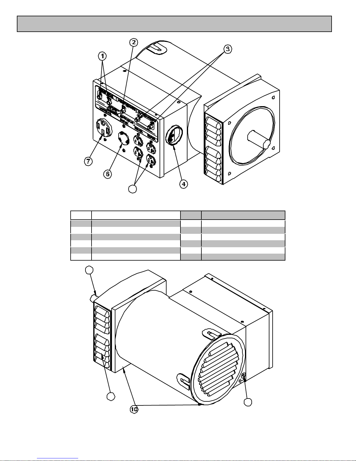
North Star 10000 BDG User manual

Proven Performance
MODEL 10000 BDG
ITEM # 165928
Belt Driven Generator
M165928A
OWNER’S MANUAL
10000 BDG
AnyQuestions, Comments,or Problems?
Call Customer Service at 1-800-270-0810
Hours: Monday - Friday 7:30 AM to 5:30 PM
Saturday 7:30 to 11:30 AM Central Standard Time
00287

1
THANK YOU
Thank you forpurchasing a NorthStar Belt Driven Generator. Your machine is designed for
long life, dependability, and the top performance you demand. Please take time now to read
through this manual so you can better understand the machine’s operation, maintenance and
safety precautions. Everyone whooperatesthisgenerator must readand understand this manual.
The time you take now will prolong your generator’s life and prepare you forits safe operation.
Enjoy the exceptional performanceof your NorthStarBelt Driven Generator.
IMPORTANT
If thismachineisused by anyone whoisnotthe owner orisloanedor rented, make certain the
operator:
- Isinstructedinthe safeand properoperationofthismachine.
- Readsand understandsthemanualspertaining to thismachine.
NOTICE
K-BAR Industries Incorporated reserves the right to make improvements in design and/or
changes in specifications at any time without incurring any obligation to install them on units
previously sold.
TABLE OF CONTENTS
Thank you 1
Specifications 2
Machine componentidentification 3
Generator features 4
Introduction 4
ANSI safety definitions 4
Rules forsafe operation 4-5
Installation 5-6
Load application 6-8
Pre-startup preparation 8
Generator care 8
Troubleshooting 9

2
SPECIFICATIONS
Item Number #165928
Maximum Output 10000 Watts (W)
Continuous Output 9600 Watts (W)
Voltage 120 /240 Volt(V)
Phase Single phase (4-wire)
Frequency 58.0-63.0 Hertz(Hz)
Power Factor 1.0 p.f.
Minimum Recommended
Engine 18 Hp
Engine Speed 3480-3780 RPM
120VReceptacle (2) 20 Amp (A) duplex(NEMA 5-20R)
30 Amp (A) twistlock(NEMA L5-30R)
120/240VReceptacle 50 Amp (A) Straight blade (NEMA14-50R)
CircuitBreaker (2) 20 Amp (A) thermal,push to resetstyle
30 Amp (A) thermal,push to resetstyle
(2) 40 Amp (A) thermal,push to resetstyle
Drive Shaft 28 mm diameter X2.38”
8 mm X1.75” keyway
Dimensions
Length 19.50” (49.5 cm)
Width 14.25” (36.2 cm)
Height 9.00” (22.9 cm)
Gross Weight 110 lb.(50 kg)

3
MACHINE COMPONENT IDENTIFICATION
Ref. Description Ref. Description
140A CircuitBreakers 7 120/240V50A Receptacle
2 30A CircuitBreaker 828 mm shaft
320A CircuitBreakers 9 Grounding screw
4 Voltmeter 10 Mounting feet
5120V 20A Duplex Receptacles 11 Fan vents
6 120V 30ATwistlockReceptacle
Figure 1 (Ref. 1-7)
00289
00290
Figure 2 (Ref. 8-11)

4
GENERATOR FEATURES
References 1-3 Circuit Breakers.
•Reference 1 - two 40 amp (A) push-to-reset
circuitbreakers.
•Reference 2 - one 30 amp (A) push-to-reset
circuitbreaker.
•Reference 3 - two 20 amp (A) push-to-reset
circuitbreakers.
Reference 4 - Voltmeter. Voltmeter needle
should be in green area during all generator load
conditions. The black line in the center on the green
area is 120V. During no load conditions, the needle
should be at orabove theblackline.
References 5-6 120V Receptacles.
•Reference 5 - Thegenerator hasa side panel
with two 120 volt (V) 20 amp (A) straight blade
receptacle duplexes (two receptacles in a common
housing). National Electrical Manufacturer’s
Association (NEMA) numberis5-20R.
•Reference 6 - This twistlock is a 120V 30A
receptacle, NEMA number L5-30R. This receptacle
acceptsNEMAplug number L5-30P, which is supplied
with the generator.
Reference 7 - 120/240V Receptacle. This
straightblade receptacleis120/240V50A,buthas two
40A circuit breakers to limit maximum current. This
receptacle accepts a NEMA plug number 14-50P,
whichissuppliedwith thegenerator.
ALWAYS use grounded male plugs. The neutral
line of the generatoris mechanically grounded to the
frame. Matching NEMA male plugs must always be
used.
Reference 8 - 28 mm diameter Shaft. The shaft
is2.375”long and hasa 8 mm key way. A taper bore
or split bore bushing is recommended for attaching
sheaves. 8 mm X1.75” key supplied withgenerator.
Reference 9 - Ground Screw. Ground the
generator via the ground screw, to a copper pipe or
rod thatisdriven intomoist soil.
Reference 10 - Mounting feet. Use these three
locations to attach the generator head in place with
7/16” grade 5 bolts. Mounting plates (item #165935)
formounting generator to a cement pad are available
through Northern and the NorthStar partscatalog.
Reference 11 - Fan Vents. Never block the vent
slots or insert objects through the slots. The closest
object should be a minimum of 3 feet away from the
vents.
INTRODUCTION
Before attempting to mount your generator,
thoroughly study the instructions and cautions in this
manual to assure you are fully acquainted with the
operation of all components of this generator. Proper
preparation, operation and maintenance will result in
operator safety, best performance and long life of the
generator.
NorthStar is constantly improving its products.
The specifications outlined herein are subject to
change without prior notice or obligation. The
purchaser and/or user assumes liability of any
modification and/or alterations on this equipment from
original design andmanufacture.
Before using, the user shall determine the
suitability of this product for its intended use and
assumesliabilitytherein.
ANSI SAFETY DEFINITIONS
DANGER indicates an imminently hazardous
situation which, if not avoided, will result in death or
seriousinjury. Thissignal wordisto belimited to the
most extremesituations.
WARNING indicates a potentially hazardous
situation which, if not avoided, could result in a
deathor serious injury.
CAUTION indicates a potentially hazardous
situation, whichifnotavoided, may resultinminor or
moderateinjury. Itmay also be used to alert against
unsafepractices.
RULES FOR SAFE OPERATIONS
Safety precautions are essential when operating
this generator. Respectful and cautious operation will
considerably lessen the possibilities of a personal
injury. This manual will warn of specific personal injury
potential, and these will be designated by the symbol:
WARNING This generator is equipped
with a grounding screw, located on the generator
frame for your protection. Always complete the
grounding path from the generator to a copper
pipe/rod that is driven into moist earth, to prevent
electrical shock.
ALWAYS use electrical cords that are in good
condition. Worn, bare, frayed or otherwise damaged
cordscan cause electric shock.
NEVER operate the generator, or handle any
electrical equipment while standing in water, while
barefoot, while hands are wet or while in the rain or
snow. Electric shockmay result.
ALWAYS use a ground fault circuit interrupter
(GFCI) in damp or highly electrical conductive areas
andon construction job sitestopreventelectric shock.

5
ALWAYS remove the spark plug or spark plug
wire before working on the engine or generator, this
preventsaccidental starting.
ALWAYS provide adequate ventilation. Do not
operate generator in any enclosed or narrow space.
Engines consume oxygen and give off deadly carbon
monoxide, a poisonous gas. Improper ventilation will
cause damage to generator and possible injury to
people.
ALWAYS remove all oil or gasoline deposits and
accumulated dirt from generator and immediate area.
Keep generator head and engine clean.
NEVER operate the generator under the following
conditions:
A. Excessive changein engine speed, slow or
fast.B. Overheating inload connectingdevices.
C. Sparking orarcsfrom generator.
D. Lossof electrical output.
E. Damaged receptacles.
F. Engine misfire.
G. Excessive vibration.
H. Enclosed compartments, or confined
areas.
I. Flame or smoke.
J. Rain, snow or wet conditions.
K. Operator non-attendance.
L. Withoutproper guarding in place.
WARNING Keep fire extinguisher close
by your generator and be familiar with how to use it.
Consult your local fire department for correct
extinguisher type.
INSTALLATION
OUTDOORS: Choose a location where the
generator will not be exposed to rain, snow or direct
sunlight. Position the generator on secure, level
ground so it will nottip or slide down a hill. Place the
generator so that the
exhaust fumeswill not be
directedtowardspeople.
The installation site
must be free from water,
moisture, or dust. All
electrical components
should be protected from
excessive moisture or
the insulation system will
deteriorate and result in
grounding or shortingout of the generating system.
Foreign matters, such as dust, dirt, sand, lint or
abrasivematerialscan cause damage tothe generator
head andengineif allowedintothecooling system.
POWER TRANSMISSION: The recommended
method to transfer the power from the engine to the
generator is by using sheaves (pulleys) and a V-belt.
The generator shaft is 28 mm diameter X 2.38” long
with a 8mm key way. The table below shows the
recommendedhorsepowerand sheaves.
The shaftspeedofthegeneratormust be between
3480-3780 RPM. Atnoload the correct speed is 3780
RPM. If the engine is a 3750 RPM engine, then a
sheave diameter ratio of 1:1 should be used. This
meansthat thediameterof the sheaveonthe engine
is the same as the diameter of the sheave on the
generator. Ifsmaller than recommended sheavesare
used, the life of the belt will be shortened. The
possibility of belt slippage also increases with a
smaller sheave.
The engineandgenerator should bemounted to a
plate or surface that can withstand the constant
vibration and stresses that will be produced. See
figure 3 for a possiblemounting configuration.
Figure 3
NOTE: Guards are removed toshow details
DANGER Always have proper guarding
of theV-belt(s) and sheaves to prevent access to any
pinchpoints. Failure to guard the power transmission
mechanismsmay resultinseriousinjury ordeath.
The user shall determine the proper belt
tensioningmethod for their specificuse.
To determine belt tension:
Measure L - thecenter to centerdistance of the two
sheaves.
Measure d - the deflection of the belt.
Engine Hp DoubleSheave Dia.
V-BeltType
Quantity
DoubleSheave Dia.
V-BeltType
Quantity
18 Hp 6.60”
B Belt
2
6.00”
3VXBelt
2
Footprint o
f
mounting feet
isshown atleft.
Use 7/16”
grade 5 bolts.
00292
00307
00039
Optional mount kit(item #165935) isavailablein
the Northerncatalogand the NorthStarparts
catalog. Includes2 platesand mountinghardware.
00291

6
Tighten orloosen belt until:
d = 0.016 X L
If the control box is not located on the correct
side for your application, it can be rotated to the
opposite side. First remove the fan vents, than
remove the four drive end bracket bolts. Rotate the
drive end bracket 180°, re-torque bolts to 17 ft•lb.
Reinstall the fan vents. Remove the four screwsat the
base of control box, rotate the control box 180°. The
voltmeterisnow on thebackofthemachineinstead of
thefront. See belowfor terminology.
DANGER Remember,exhaust fumesare
deadly carbon monoxide gas, and must be vented to
theoutside wherethere are no people. Cooling air of
sufficient amounts must be brought in and exhausted
out to ensure proper cooling of the engine and
generator.
If you desire to direct couple the generator to an
engine,great care must be taken to align the shaft of
the generator and engine to within the specified
tolerancesof the chosen coupler.
NEVER install your generator inside confined
areas. Insideinstallation can cause health hazards or
death.
LOAD APPLICATION
Itisimportanttodetermine the total electrical load
beforeitisconnected to thegenerator. The two major
factorsin determiningthe lifeof a generator head are:
heat build up, caused by overloading the generator
and corrosive contaminants, that attack the wiring
insulation. If the generator is overloaded, the wires
become excessively hot and cause the insulation to
break down, reducing its ability to resist corrosive
contaminants. Over time the effectiveness of the
insulationiseliminatedand a dead short can result.
Always compare the generator nameplate data
with that of the equipment to be used to ensure that
watts, volts, amperage, and frequency requirements
are suitable for operating equipment. The wattage
listed on the equipment nameplate is its rated output.
However, some equipment may require three to ten
times more wattage than its rating on the nameplate,
as the wattage is influenced by the equipment
efficiency, power factor and starting system. NOTE: If
wattage is not given on equipment nameplate,
approximate wattage may be determined by
multiplying nameplate voltage by nameplate
amperage.
VOLTS X AMPS = WATTS
Example: 120V X 5A = 600W
When connecting a resistive load such as
incandescentlights, heatersor common electric power
tools, a capacity of up to the generator full rated
wattage outputcanbe used.
When connecting a resistive-inductive load such
as a fluorescent or mercury light, transformers or
inductive coils, a capacity of up to 0.6 times the
generator’sfull rated output can beused.
Always allow the generator to reach operating
speed before a load isapplied.
STARTING ELECTRICMOTORS
Electric motors require much more current (amps)
to start than to run. Some motors, particularlylow cost
split-phasemotors, are very hard to start and require 5
to 7timesmore currentto start than to run. Capacitor
motors are easier to start and usually require 2 to 4
timesasmuch current to start than to run. Repulsion
Induction motors are the easiest to start and require
1.5to2.5timesasmuch to start thantorun.
Most fractional motors take about the same
amount of current to run them whether they are of
Repulsion-Induction (RI), Capacitor (Cap), or Split-
Phase (SP) type. The following chart shows the
approximate current required to start and run various
types and sizes of 120 volt 60 cycle electric motors
under variousconditions.
120V,60 HzMotors Starting Amps
Hp motor Running
Watts RI type Cap type SP type
1/6 525 7-11 9-18 16-22
1/4 700 9-15 12-23 22-32
1/3 875 11-18 14-29 26-35
1/2 1175 15-25 20-40 NA
11925 24-40 32-64 NA
1 1/2 2400 30-50 40-80 NA
22900 36-60 48-96 NA
3 4075 51-85 68-136 NA
56750 84-140 112-224 NA
00298

7
The figures given above are for an average load
such as a blower or fan. If the electric motor is
connected to a hard starting load such as an air
compressor, it will require more starting current. If it is
connected to a light load or no load such as a power
saw, it will require less starting current. The exact
requirement will also vary with the brand or design of
themotor.
Generators respond to severe overloading
differently thanthe power line. When overloaded, the
engineisnotable tosupply enough powerto bring the
electric motor up to operating speed. The generator
responds to the high initial starting current, but the
engine speed drops sharply. The overload may stall
theengine. If allowed to operate at very low speeds,
the electric motor starting winding will burn out in a
short time. The generator head windingmightalso be
damaged.
Running thegenerator underthese conditionsmay
resultin damage to the generator stator as well as the
electric motor windings. Because the heavy surge of
current is required for only an instant, the generator
will not be damaged if it can bring the motor up to
speed in a few seconds. If difficulties in starting a
motor are experienced, turn off all other electrical
loads and if possible reduce the load on the electric
motor.
EXTENSION CORDS
When electric power is to be provided to various
loads at some distance from the generator, extension
cords can be used. These cords should be sized to
allowfor distance in length and amperage so that the
voltage dropbetween the set and point of use is held
to a minimum.
Current/Power Maximum Extension Cord Length
Amps
at
240V
Load
(watts) #10
Ga.
Cord
#12
Ga.
Cord
#14
Ga.
Cord
#16
Ga.
Cord
10 2400 250’ 150’ 100’ 75’
20 4800 125’ 75’ 50’ 25’
30 7200 60’ 35’ 25’ 10’
40 9600 30’ 15’ 10’ *
50 12000 15’ ***
CAUTION: Equipment damage can resultfrom the
low voltage caused by using an extension cord with a
small wire size.
Use this chart to estimate the total load on your
generator.
For Determining Generator Load Requirements
Device Running Watts
Air Conditioner (12,000 Btu) 1700 (a)
Battery Charger (20 Amp) 500
Belt Sander (3”) 1000
Chain Saw 1200
Circular Saw (6-1/2”) 900
Coffee Maker 1000
Compressor (1 HP) 2000 (a)
Compressor (3/4 HP) 1800 (a)
Compressor (1/2 HP) 1400 (a)
CurlingIron 700
Dishwasher 1200
Edge Trimmer 500
Electric Nail Gun 1200
Electric Range (oneelement) 1500
ElectricSkillet 1250
Freezer 800(b)
Furnace Fan (1/3 HP) 1200 (a)
Hair Dryer 1200
Hand Drill (1”) 1100
Hand Drill (1/2”) 875
Hand Drill (3/8”) 500
Hand Drill (1/4”) 250
HedgeTrimmer 450
HomeComputer 150
Impact Wrench 500
Jet Pump 800 (a)
LawnMower 1200
LightBulb 100
MicrowaveOven 700
MilkCooler 1100 (a)
Oil Burneron Furnace 300
Oil FiredSpace Htr(140,000 Btu) 400
Oil Fired Space Htr (85,000 Btu) 225
Oil Fired Space Htr (30,000 Btu) 150
Oven 4500
Paint Sprayer, Airless (1/3 HP) 600 (a)
PaintSprayer, Airless(handheld) 150
Radio 200
Refrigerator 600(b)
Slow Cooker 200
Submersible Pump (1-1/2 HP) 2800 (a)
SubmersiblePump (1 HP) 2000 (a)
Submersible Pump (1/2 HP) 1500 (a)
Sump Pump 600 (a)
TableSaw (10”) 2000 (a)
Television 500
Toaster 1000
Vacuum cleaner 250
VCR 70
Water Heater 3000
Weed Trimmer 500
(a) Hard-starting motors require 3 to 5 times the
rated running watts.
(b) These loads may require up to 15 minutes to
restart due to its normal build up of compressor head
pressure.
NOTE: For extremely hard to start loads such as
air conditioners and air compressors, consult the
equipment dealer to determine the maximum wattage.
PRE-START UP PREPARATIONS
Yourgenerator hasbeen thoroughly testedpriorto
shipment from the factory. However, damage can
occur during shipping, so be sure to check for
damagedparts,loose ormissing nutsandbolts. If the
aforementioned problems occur, call customer service
at 1-800-270-0810.
*Not recommended

8
GROUNDING - All units must be grounded. Drive
a 3/4” or 1” copper pipeor rod intothe ground close to
the generator. The pipe/rod must penetrate moist
earth. Connect an approvedground clamp to thepipe.
Run a10 gauge wire from the clamp to the generator
ground screw. Do not connect to a water pipe or a
groundused bya radio system.
OPERATING SPEED
The generator must be run at the correct speed in
order to produce the proper electrical voltage and
frequency.
The output voltage should be checked to ensure
the generator is working properly subsequent to
connecting a load to the generator. Failure to do so
could result in damage to equipment plugged into the
unit and possible injury to the individual.
All engineshave a tendency to slow down when a
load isapplied. When the electrical load is connected
to the generator, the engine is more heavily loaded,
and as a result the speed drops slightly. This slight
decrease in speed, together with the voltage drop
within the generator itself, results in a slightly lower
voltage whenthegeneratorisloaded to itsfull capacity
than when it is running with no load. The slight
variationhas no appreciable effect in the operation of
motors, lights and most appliances. Electronic
equipmentand clockswill be effected if correct RPM is
notmaintained. SeeLoad vs. Output chart
Load Output
Percent of
Generator
Output
Speed
(RPM) Frequency
(Hz) Generator
voltage at 120V
Receptacle
0 % 3780 63.0 125V
50 % 3600 60.0 122V
100% 3480 58.0 118V
Output voltage should be checked periodically to
ensure continued proper operation of the generating
plantandappliances, it can be checked withaportable
meter. Frequency canbe checkedby using anelectric
clock with a sweep second hand. Timed against a
wrist watch ora stop watch the clockshould be correct
within +/- 2 seconds per minute. All speed setting
adjustmentsshould be doneby a qualified technician.
GENERATOR CARE
The generator head isa two pole, 3600 RPM, 60
Hz, brushless, revolving field and synchronous type
withtwo sealed radial roller bearings.
Proper care and maintenance are necessary to
ensure alongtrouble free life.
Exercising The Generator - The generator
should be operated every four weeks.. This is
accomplished by starting the engine and applying a
load for 10 to 15 minutes. This will dry out any
moisture that hasaccumulated in the windings. If left,
this moisture can cause corrosion in the winding.
Frequent operation of the generator will also ensure
that the set is operating properly should it be needed
inanemergency.
Generator Maintenance - The generator head is
brushlessand maintenance free. Anymajor generator
service including the installation or replacement of
partsshould be performed onlyby a qualifiedelectrical
service technician. USE ONLY NorthStarAPPROVED
REPAIR PARTS AVAILABLE AT 1-800-270-0810.
A. Bearing - The bearings used in this generator
are a heavy duty, sealed ball bearing type. They
require nomaintenance or lubrication.
B. Receptacles - Quality receptacles have been
utilized. If a receptacle should become cracked or
otherwise damaged, replace it. Using cracked or
damaged receptacles can be both dangerous to the
operator and destructiveto the equipment.
WARNING, Stand-by Operation
If your generator is to be used as a standby
electric power source in case of utility failure, it must
be installed by a registered and licensed electrician
and in compliance with all applicable state and local
electrical codes. Also,local Fire Departmentsmust be
consulted concerning proper and safe handling
procedures for gasoline. NEVER connect any
generator toanyexisting electrical system without an
isolating, UL approved transfer switch, installed by a
licensedelectrician.

9
TROUBLESHOOTING
Problem Possible Causes Possible Remedies
Voltagetoolow. a) Engine speed too slow.
b) Generatorisoverloaded.
c) Belt slippage. (or coupler slippage)
a) Bring generator to a qualified
technician for adjustment.
b) Reduce theload.(See Load
Application section ofthismanual.)
c) Tighten belt(s). (or tighten coupler)
Circuit breaker trips. a) Defective load connected to generator.
b) Defectivereceptacle.
c) Generator overloaded.
a) Disconnectload.
b) Replacereceptacle.
c) Reduce theload.(See Load
Application section ofthismanual.)
Voltage too high. a) Engine speed too high. a) Bring generator to a qualified
technician for adjustment.
Generatoroverheating. a) Generatorisoverloaded.
b) Insufficient ventilation.
a) Reduce theload.(See Load
Application section ofthismanual.)
b) Make sure thereisatleast 3 feetof
clearance on all sides of generator.
No output voltage. a) Defectiveload connected to generator.
b) Broken orloose wire.
c) Defective receptacle.
d) Defectivestator.
e) Defective rotor.
f) Defective capacitor.
g) Defective circuit breaker.
h) Belt(s) isslippingor broken. (or coupler
slipping or broken)
a) Disconnectload.
b) Bring generator to a qualified
technician for repair.
c) Replacereceptacle.
d) Bring generator to a qualified
technician for repair.
e) Bring generator to a qualified
technician for repair.
f) Bring generator to a qualified
technician for repair.
g) Bring generator to a qualified
technician for repair.
h) Tighten or replacebelt(s). (tighten or
replace coupler)
Table of contents
Other North Star Inverter manuals
Popular Inverter manuals by other brands

TECO-Westinghouse
TECO-Westinghouse E510 Start-up and installation manual

SOLIS
SOLIS S6-GC25K-US user manual

Mitsubishi Electric
Mitsubishi Electric 700 Series instruction manual

Unical
Unical STILE 27 Instructions for installation, maintenance and use

Jntech
Jntech JNP75KH-V3 user manual

Fujitsu
Fujitsu AIRSTAGE J-IIIL Design & technical manual