Northern Industrial Tools ARC 70 164620 User manual

Read carefully and understand RULES FOR SAFE OPERATION and instructions before
operating. Failure to follow the safety rules and other basic safety precautions may
result in serious personal injury.
ARC 70
Item# 164620
OPERATOR’S MANUAL

ARC 70
Item# 164620
Operation Instructions
For technical questions and replacement parts, please call 1-800-222-5381.
Thank you very much for choosing a NORTHERN TOOL + EQUIPMENT CO., product. For
future reference, please complete the owner’s record below:
Model:________________ Purchase Date:___________________
Save the receipt, warranty information and this owner’s manual. It is important that you read
the entire manual to become familiar with this product before using it.
This machine is designed for certain applications only. Northern Tool + Equipment strongly
recommends that this machine not be modified and/or used for any application other than
that for which it was designed. If you have questions relative to a particular application, DO
NOT use the machine before you contact Northern Tool + Equipment to determine if it can be
performed on the product.
Before using this welding unit, please read the following instructions carefully.
SAVE THIS MANUAL
You will need this manual for the safety warnings and precautions, assembly (if any), operat-
ing, inspection, maintenance and cleaning procedures, parts list and assembly diagram. Keep
your receipt and this manual in a safe and dry place for future reference.
Please read and save these instructions. Read through this owner’s manual carefully before
using product. Protect yourself and others by observing all safety information, warnings, and
cautions. Failure to comply with instructions could result in personal injury and/or damage to
product or property. Please retain instructions for future reference.
1
AC Stick Welder
Northern Industrial Welder
Operating Instructions and Parts Manual ARC 70
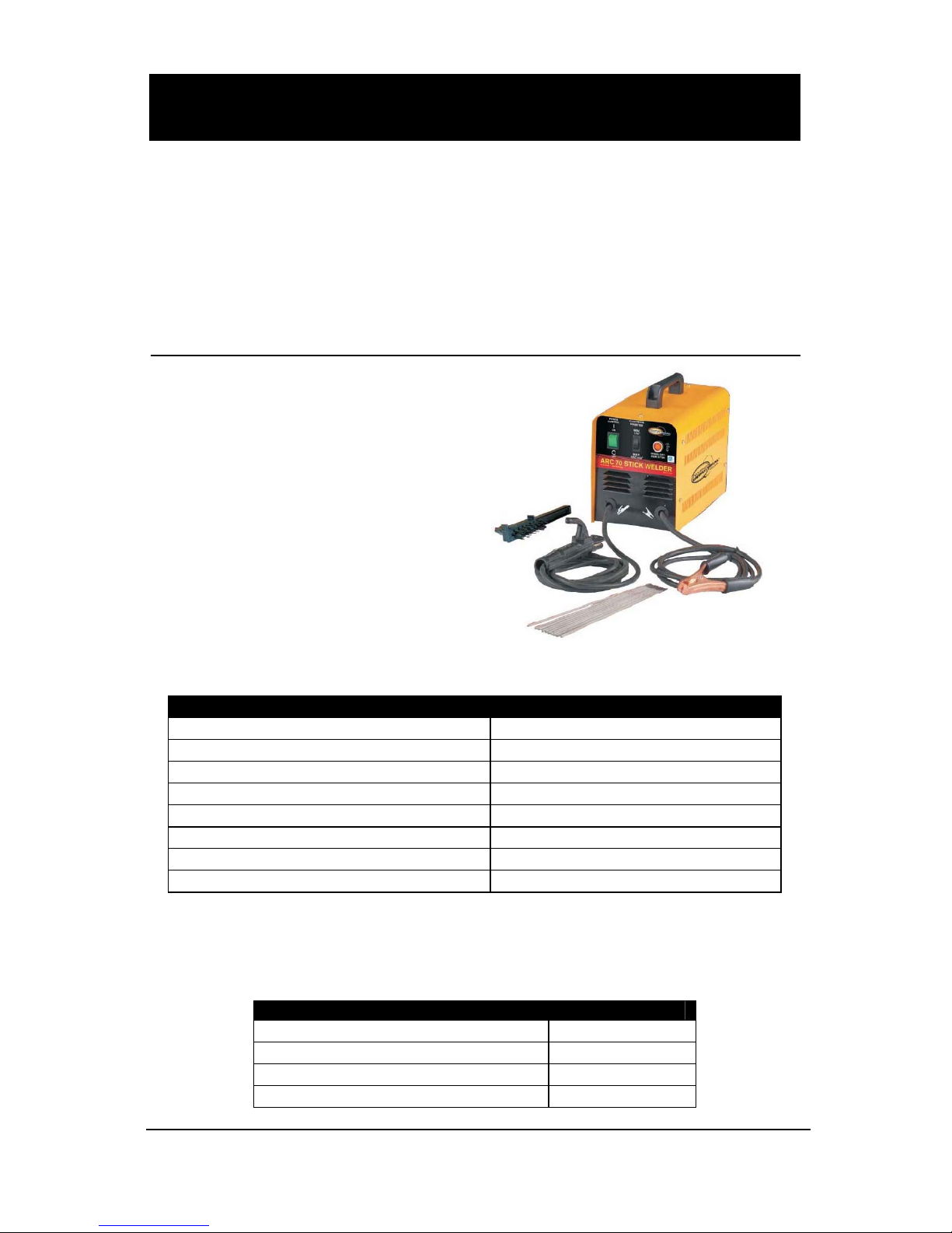
Description
Arc70 is a portable AC Arc Welder.
It uses single phase 115VAC (110-
120V), 60HZ. Power requires a 20
amp time delayed fuse or circuit
breaker. Out put is 50 amps at 20%
duty cycle, OCV 42 VDC. Also
includes load and thermal protection.
Designed to use for mild steel or
alloys in DIY applications. Welds up
to 1/8” mild steel.
Specifications and Dimension
MODEL SPECIFICATION
Power supply 1ph-115V-60HZ
No-load voltage (OCV) 42V
Output Range 50/70A
Duty cycle 20%
Suggested electrodes E6011, E6013, E7014, E7018AC
Electrode Diameter 1/16”, 5/64”
Dimension (L x W x H) 13”x 6.7”x 10.2”
Weight 27Ibs
Removing from the carton
1.1 Remove cartons, bags or Styrofoam containing the welder and accessories.
1.2 Check the contents with the packing list below.
ITEM QTY.
Portable Arc Welder 1 unit
Hammer/brush 1pc
Operator’s Manual 1pc
Welding rod 1bag
Northern Industrial Welder ARC 70
Operating Instructions and Parts Manual
2
1.3 After unpacking unit, inspect carefully for any damage that may have
occurred during transit. Check for loose, missing, or damaged parts. Shipping
damage claim must be filed with carrier.
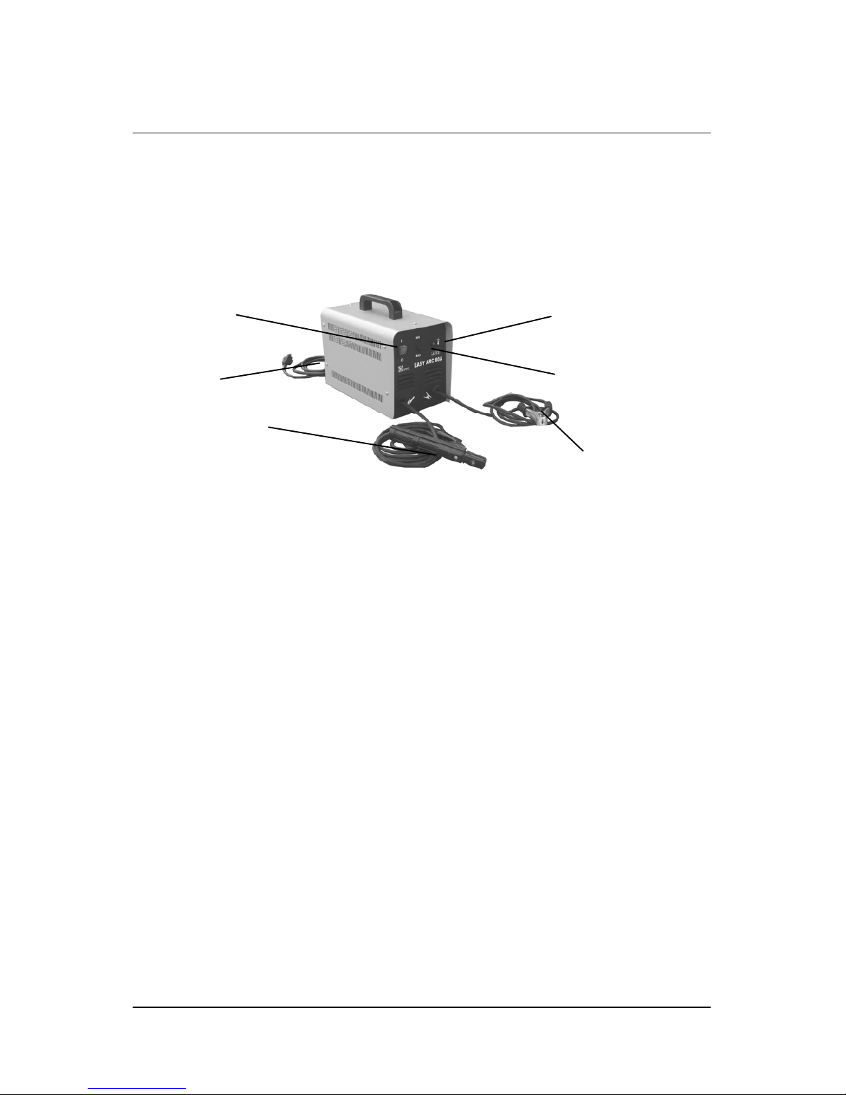
Know your Welder
ON/OFF switch
In the “off” position no power is being supplied to the welder. In the “ON” position
power is supplied to the main transformer and control circuit and electrode.
MIN/MAX switch
MIN/MAX switch is on the front panel of machine, it controls the current flow. MIN
is for 1/16” electrodes and MAX is for 5/64”.
Thermal indicator
If welding at high amperage for an extended time the duty cycle can be exceeded,
the overload light will come on (orange), the machine will stop working until the
temperature decreases to the acceptable operating temperature range. If the
overload light comes on it will take about 15 minutes for the unit to cool down and
be ready to use.
Ground cable and clamp
The ground cable and clamp is attached to the work piece to complete the flow of
current needed to weld.
Welding cable and electrode Holder
The electrode holder is where the electrodes are held for welding.
Power cord
The power cord connects the welder to the 115 volt power supply. Plug the 15
amp plug into a 115 volt/20 amp receptacle to supply power to the welder
ON/OFF Switch
Power Cord
Welding Cable and
Electrode Holder
MAX/MIN Switch
Thermal overload Indicator
Ground Cable/clamp

Northern Industrial Welder ARC 70
Operating Instructions and Parts Manual
1
General Safety Information
1.1 Your Welding Environment
-Keep the environment you will be
welding in free from flammable
materials.
-Always keep a fire extinguisher
accessible to your welding
environment.
-Always have a qualified person
install and operate this equipment.
-Make sure the area is clean, dry and
ventilated. Do not operate the welder
in humid, wet or poorly ventilated
areas.
-Always have your welder maintained
by a qualified technician in
accordance with local, state and
national codes.
-Always be aware of your work
environment. Be sure to keep other
people, especially children, away
from you while welding.
-Keep harmful arc rays shielded from
the view of others.
-Mount the welder on a secure bench
or cart that will keep the welder
secure and prevent it from tipping
over or falling.
1.2 Your Welder’s Condition
-Check all cables, power cord and
welding cable to be sure the
insulation is not damaged. Always
replace or repair damaged
components before using the welder.
-Check all components to ensure they
are clean and in good operating
condition before use.
1.3 Use of Your Welder
Do not operate the welder if the
output cable/electrode holder, ground
cable/clamp or electrode is wet. Do
not immerse them in water. These
components and the welder must be
completely dry before attempting to
use them.
-Follow the instructions in this manual.
-Keep welder in the off position when
not in use.
-Connect ground lead/clamp as close
to the area being welded as possible
to ensure a good ground.
-Do not allow any body part to come
in contact with the welding electrode
if you are in contact with the material
being welded, ground or electrode
from another welder.
-Do not weld if you are in an awkward
position. Always have a secure
stance while welding to prevent
accidents. Wear a safety harness if
working above ground.
-Do not drape cables over or around
your body.
-Wear a full coverage helmet with
appropriate shade (see ANSI Z87.1
safety standard) and safety glasses
while welding.
-Wear proper gloves and protective
clothing to prevent your skin from
being exposed to hot metals, UV and
IR rays.
-Do not overuse or overheat your
welder. Allow proper cooling time
between duty cycles.
-Keep hands and fingers away from
moving parts.
-Do not point electrode at any body
part of yourself or anyone else.
Northern Industrial Welder ARC 70
Operating Instructions and Parts Manual
4
-Always use this welder in the rated
duty cycle to prevent excessive heat
and failure.
1.4 Specific Areas of Danger,
Caution or Warning
Electrical Shock
Electric arc welders can
produce a shock that
can cause injury or
death. Touching electrically live parts
can cause fatal shocks and severe
burns. While welding, all metal
components connected to the
electrode are electrically hot. Poor
ground connections are a hazard, so
secure the ground lead before
welding.
-Wear dry protective apparel: coat,
shirt, gloves and insulated footwear.
-Insulate yourself from the work piece.
Avoid contacting the work piece or
ground.
- Do not attempt to repair or maintain
the welder while the power is on.
-Inspect all cables and cords for any
exposed wire and replace
immediately.
-Use only recommended replacement
cables and cords.
-Always attach ground clamp to the
work piece or work table as close to
the weld area as possible.
-Do not touch the welding electrode
and the ground or grounded work
piece at the same time.
-Do not use a welder to thaw frozen
pipes.
Fumes and Gases
-Fumes emitted from the
welding process displace
clean air and can result in
injury or death.
-Do not breathe in fumes emitted by
the welding process. Make sure your
breathing air is clean and safe.
-Work only in a well-ventilated area or
use a ventilation device to remove
welding fumes from the environment
where you will be working.
-Do not weld on coated materials
(galvanized, cadmium plated or
containing zinc, mercury or barium).
They will emit harmful fumes that are
dangerous to breathe. If necessary
use a ventilator, respirator with air
supply or remove the coating from the
material in the weld area.
-The fumes emitted from some
metals when heated are extremely
toxic. Refer to the material safety
data sheet for the manufacturer’s
instructions.
-Do not weld near materials that will
emit toxic fumes when heated.
Vapors from cleaners, sprays and
degreasers can be highly toxic when
heated.
UV and IR Arc Rays
The welding arc
produces ultraviolet (UV)
and infrared (IR) rays
that can cause injury to your eyes
and skin. Do not look at the welding
arc without proper eye protection.
-Always use a helmet that covers
your full face from the neck to top of
head and to the back of each ear.
-Use a lens that meets ANSI
standards and safety glasses. For
welders under 160 Amps output, use
a shade 10 lens; for above 160 Amps,
use a shade 12. Refer to the ANSI
standard Z87.1 for more information.
-Cover all bare skin areas exposed to
the arc with protective clothing and
shoes. Flame-retardant cloth or

Northern Industrial Welder ARC 70
Operating Instructions and Parts Manual
5
leather shirts, coats, pants or
coveralls are available for protection.
-Use screens or other barriers to
protect other people from the arc rays
emitted from your welding.
-Warn people in your welding area
when you are going to strike an arc
so they can protect themselves.
Fire Hazards
Do not weld on containers
or pipes that contain or
have had flammable,
gaseous or liquid combustibles in
them. Welding creates sparks and
heat that can ignite flammable and
explosive materials.
-Do not operate any electric arc
welder in areas where flammable or
explosive materials are present.
-Remove all flammable materials
within 35 feet of the welding arc. If
removal is not possible, tightly cover
them with fireproof covers.
-Take precautions to ensure that
flying sparks do not cause fires or
explosions in hidden areas, cracks or
areas you cannot see.
-Keep a fire extinguisher close in the
case of fire.
-Wear garments that are oil-free with
no pockets or cuffs that will collect
sparks.
-Do not have on your person any
items that are combustible, such as
lighters or matches.
-Keep work lead connected as close
to the weld area as possible to
prevent any unknown, unintended
paths of electrical current from
causing electrical shock and fire
hazards.
-To prevent any unintended arcs,
keep electrode away from grounded
materials until you are ready to weld.
Hot Materials
Welded materials are hot
and can cause severe
burns if handled
improperly.
-Do not touch welded materials with
bare hands.
-Do not touch electrode after welding
until it has had time to cool down.
Sparks/Flying Debris
Welding creates hot
sparks that can cause
injury. Chipping slag off
welds creates flying debris.
-Wear protective apparel at all times:
ANSI-approved safety glasses or
shield, welder’s hat and ear plugs to
keep sparks out of ears and hair.
Electromagnetic Field
-Electromagnetic fields
can interfere with various
electrical and electronic
devices such as pacemakers.
-Consult your doctor before using any
electric arc welder or cutting device
-Keep people with pacemakers away
from your welding area when welding.
-Do not wrap cable around your body
while welding.
-Wrap MIG gun and ground cable
together whenever possible.
-Keep electrode cable/holder and
ground cables on the same side of
your body.
Shielding Gas Cylinders
Can Explode
High pressure cylinders
can explode if damaged, so treat
them carefully.

Northern Industrial Welder ARC 70
Operating Instructions and Parts Manual
6
-Never expose cylinders to high heat,
sparks, open flames, mechanical
shocks or arcs.
-Do not touch cylinder with electrode
-Do not weld on the cylinder.
-Always secure cylinder upright to a
cart or stationary object
-Keep cylinders away from welding or
electrical circuits.
-Use the proper regulators, gas hose
and fittings for the specific application.
-Do not look into the valve when
opening it
-Use protective cylinder cap
whenever possible
1.5Proper Care, Maintenance and
Repair
-Repair to internal component should
only be done by a qualified repair
center.
-Always have power disconnected
when working on internal components.
- Do not touch or handle PC board
without being properly grounded with
a wrist strap. Put PC board in static
proof bag to move or ship.
-Do not put hands or fingers near
moving parts such as a fan
Assembly
No assembly is required for this unit.
Installation
1. Power requirement
This welder uses AC single phase
115v (110-120V), 60HZ/20amp time
delayed fuse or circuit breaker. DO
NOT OPERATE THIS UNIT if the
ACTUAL power source voltage is less
than 105 volts ac or greater than 132
volts ac.
• High voltage danger from power
source! Consult a qualified
electrician for proper installation of
receptacle. This welder must be
grounded while in use to protect
the operator from electrical shock.
• Do not remove grounding prong
or alter the plug in any way. Do
not use any adapters between the
welder’s power cord and the power
source receptacle. Make sure the
POWER switch is OFF when
connecting your welder’s power
cord to a properly grounded 115
Vac, 60Hz, single phase, 20 amp
power source.
2. Extension cord
It is strongly recommended that an
extension cord should not be used
because of the voltage drop it
produces. This drop in voltage can
affect the performance of the welder.
If you need to use an extension cord
it must be a #12 gauge cord or larger.
Do not use an extension cord over 25
ft. in length.
3. Setting up the work piece
3.1 Welding positions
There are four basic positions for
welding: Flat, Horizontal, vertical and
overhead. Flat welding is generally
easier, faster, and allows for better
penetration. If possible, the work
piece should be positioned so that the
bead will run on a flat surface.
3.2 Preparing the Joint
Before welding, the surface of work
piece needs to be free of dirt, rust,
scale, oil or paint or it will create
brittle and porous weld. If the base
metal pieces to be joined are thick or
heavy, it may be necessary to bevel
the edges with a metal grinder, the

Northern Industrial Welder ARC 70
Operating Instructions and Parts Manual
7
correct bevel should be around 60
degree. See following picture:
Based on different welding position,
there are different welding joint, see
following images for more information
4. Ground clamp connection
Clear any dirt, rust, scale, oil or paint
on the ground clamp. Make certain
you have a good solid ground
connection. A poor connection at the
ground clamp will waste power and
heat. Make sure the ground clamp
touches the metal.
5. Electrode
The welding electrode is a rod coated
with a layer of flux. When welding,
electrical current flows between the
electrode (rod) and the grounded
metal work piece. The intense heat of
the arc between the rod and the
grounded metal melts the electrode
and the flux. The most popular
electrodes are:
-E6011 60,000 PSI tensile strength
deep penetrating applications.
-E6013 60,000 PSI tensile strength
used for poor fit up applications
-E7014 70,000 PSI tensile strength
used for high deposition and fast
travel speeds with light penetration
-E7018AC 70,000 PSI tensile
strength, Used for out of position and
tacking.
6. Selecting the proper electrode
The type and thickness of metal and
the position of the work piece
determine the electrode type and the
amount of heat needed in the welding
process. Heavier and thicker metals
required more amperage. It is best to
practice your welds on scrap metal
which matches the metal you intend
to work with to determine correct heat
setting and electrode choice. See the
following helpful trouble shooting tips
to determine if you are using a correct
electrode
1. When proper rod is used:

Northern Industrial Welder ARC 70
Operating Instructions and Parts Manual
8
a. The bead will lay smoothly over
the work without ragged edges
b. The base metal puddle will be as
deep as the bead that rises
above it
c. The welding operation will make
a crackling sound similar to the
sound of bacon frying
2. When a rod too small is used:
a. The bead will be high and
irregular
b. The arc will be difficult to
maintain
3. When the rod is too large
a. The arc will burn through light
metals
b. The bead will undercut the work
c. The bead will be flat and porous
d. Rod may be freeze or stick to
work piece
Note: Rate of travel over the work
also affects the weld. To ensure
proper penetration and enough rod
deposit, the arc must be moved
slowly and evenly along the weld
seam.
Operation
1. Setting the amperage control
The welder has a two step output
current control. It is capable of
welding with 1/16"and 5/64"
electrodes.
Use MIN setting for 1/16” electrodes
and MAX for 5/64 electrodes. It is
best to practice your welds on scrap
metal which matches the metals you
intend to work with to determine
correct setting for your job. The
electrode type and the thickness of
the work piece metal determine the
amount of heat needed in the welding
process. Heavier and thicker metals
require more voltage (amperage),
whereas lighter and thinner metals
require less voltage (amperage).
2. Welding techniques
The best way to teach yourself how to
weld is with short periods of practice
at regular intervals. All practice welds
should be done on scrap metal that
can be discarded. Do not attempt to
make any repairs on valuable
equipment until you have satisfied
yourself that your practice welds are
of good appearance and free of slag
or gas inclusions.
2.1Holding the electrode
The best way to grip the electrode
holder is the way that feels most
comfortable to you. Position the
Electrode to the work piece when
striking the initial arc it may be
necessary to hold the electrode
perpendicular to the work piece.
Once the arc is started the angle of
the electrode in relation to the work
piece should be between 10 and 30
degrees. This will allow for good
penetration, with minimal spatter.
2.2 Striking the arc
EXPOSURE TO A WELDING ARC
IS EXTREMELY HARMFUL TO THE
EYES AND SKIN.
• Never strike an arc or begin
welding until you have adequate
protection.
• Wear flameproof welding gloves,
heavy long-sleeved shirt, trousers
with out cuffs, high-topped shoes
and a welding helmet or shield.
Scratch the work piece with the end
of electrode to start arc and then
raise it quickly about 1/8 inch gap
between the rod and the work piece,
see following picture

Northern Industrial Welder ARC 70
Operating Instructions and Parts Manual
9
It is important that the gap be
maintained during the welding
process and it should be neither too
wide or too narrow. If too narrow, the
rod will stick to the work piece. If too
wide, the arc will be extinguished.
It needs much practice to maintain
the gap. When the rod sticks to the
work piece, gently rock it back and
forth to separate them. A stuck
electrode will cause a short circuit
and the circuit breaker of thermal
overload will shut the welder off.
A good arc is accompanied by a crisp,
cracking sound. The sound is similar
to that made by bacon frying. To lay a
weld bead, only 2 movements are
required; downward and in the
direction the weld is to be laid, as in
following figure:
2.3 Types of weld bead
The following paragraphs discuss the
most commonly used arc welding
beads.
The stringer bead Formed by
traveling with the torch in a straight
line while keeping the wire and nozzle
centered over the weld joint.
The weave bead Used when you
want to deposit metal over a wider
space than would be possible with a
stringer bead. It is made by weaving
from side to side while moving with
the torch. It is best to hesitate
momentarily at each side before
weaving back the other way
penetration.
2.4 Welding position
Flat position It is easiest of the
welding positions and is most
commonly used. It is best if you can
weld in the flat position if at all
possible as good results are easier to
achieve.
The horizontal position it is
performed very much the same as
the flat weld except that the angle is
different such that the electrode, and
therefore the arc force, is directed
more toward the metal above the
weld joint. This more direct angle
helps prevent the weld puddle from
running downward while still allowing
slow enough travel speed to achieve
Northern Industrial Welder ARC 70
Operating Instructions and Parts Manual
10
good penetration. A good starting
point for your electrode angle is about
30 degrees DOWN from being
perpendicular to the work piece.
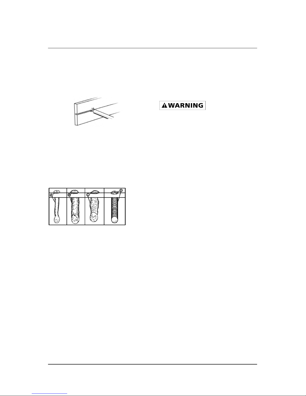
2.5 Judging a good weld bead
When the skill of striking and holding
an arc has been learned, the next
step is learning how to run a good
bead. The first attempts in practice
will probably fall short of acceptable
weld beads. Too long of an arc will be
held or the travel speed will vary from
slow to fast (see following)
A. Weld speed is too fast.
B. Weld speed is too slow.
C. Arc is too long.
D. Ideal weld.
A solid weld bead requires that the
electrode be moved slowly and
steadily along the weld seam. Moving
the electrode rapidly or erratically will
prevent proper fusion or create a
lumpy, uneven bead. To prevent
ELECTRIC SHOCK, do not perform
any welding while standing, kneeling,
or lying directly on the grounded work.
2.6 Finish the bead
As the coating on the outside of the
electrode burns off, it forms an
covering of protective gasses around
the weld. This prevents air from
reaching the molten metal and
creating an undesirable chemical
reaction. The burning coating,
however, forms slag. The slag
formation appears as an
accumulation of dirty metal scale on
the finished weld. Slag should be
removed using a chipping hammer.
CHIPPING THE SLAG FROM A
WELD JOINT CAUSES SMALL
CHIPS OF SLAG TO FLY
THROUGH THE AIR
• Slag flying through the air can
cause eye injury or injury to parts
of the head, hands or exposed
portions of the body.
• Wear goggles or eye glasses with
side shields and protect the hands
and other exposed parts of the
body with protective garments, or
if possible, work with a shield
between the body and the work
piece.
The intense heat produced at the arc
sets up strains in the metal joined by
welding. Chipping the weld not only
removes the slag left behind in the
welding but relieves the internal
strains developed by the heating and
cooling process.
Maintenance
The welder needs regular
maintenance.
Periodically clean dust, dirt, grease,
etc. from your welder. Every six
months, or as necessary, remove the
cover panel from the welder and air-
blow any dust and dirt that may have
accumulated inside the welder.
Replace power cord, ground cable,
ground clamp, or electrode assembly
when damaged or worn.
MINOR AND ROUTINE
MAINTENANCE

Northern Industrial Welder ARC 70
Operating Instructions and Parts Manual
11
The welder should not be exposed to
rain or high humidity. Store in a clean
dry location free from corrosive gas,
dust and high humidity. Temperature
ranges from 10eF120°F and a
relative humidity less than 90%.
When transporting or storing the
welder after use, it is recommended
to repack the product as it was
received for protection. (Cleaning is
required before storage and you must
seal the plastic bag in the box for
storage
Trouble shooting Chart
Symptom (s) Possible Causes(s) Corrective Action(s)
Welder does not
work when the
turn on the main
switch
1. No power input
2. The power cord or power plug
is broken
3. Main switch is broken
4. Transformer is broken
1. Check circuit or fuse of
power source
2. Replace power cord
3. Replace switch
4. Replace the transformer
Welder does not
weld properly
1. Incorrect power input
2. Inadequate current at output
3. Poor connection of output
cable
4. Dirty surfaces
5. Wrong welding wire
1. Check the power source
2. Check for proper
grounding to the work piece.
3. Check output connection
4. Clean surfaces
5. Use correct wire
Welder blows
circuit breaker or
fuse
Wrong circuit breaker or fuse in
power supply
Check the circuit breaker or
fuse in power source should
be 20amp
Arc is hard to
start
1. The wrong electrode, too big
2. Base metal not grounded
properly
1. Use correct electrode
2. Make sure the connection
is good
Welding bead too
thin
The welding speed is too fast Slow down the welding
speed
Welding bead too
thick
The welding speed is too slow Speed up the welding speed
Electrode sticks
to work piece
Electrode is kept to contact work
piece too long time when
starting arc
After arc starting, move the
electrode away from the
work piece immediately
Poor welding
performance,
spatter
1. Damp electrode
2. Wrong type electrode
use dry electrode
use correct electrode
Others Call Tech Help

Northern Industrial Welder ARC 70
Operating Instructions and Parts Manual
12
Main Circuit Chart

Northern Industrial Welder ARC 70
Operating Instructions and Parts Manual
13
Illustrated Parts List

Northern Industrial Welder ARC 70
Operating Instructions and Parts Manual
14
Repair Parts List
Reference
number Description Part number Qty
1 Ground clamp 1.05.80.04 1
2 Cable holder 2.05.05.201 3
3 Front panel 1.05.81.01 1
4 Foot 2.05.05.016 4
5 Bottom 1.05.81.02 1
6 Back panel 1.05.81.04 1
7 Power cord with plug 2.03.05.140 1
8 Handle 2.05.08.027-1 1
9 Enclosure 1.05.81.03 1
10 Transformer 1.05.80.17 1
11 Thermal relay 2.07.36.410 1
12 LBD 1.05.81.07 1
13 Setting switch 2.07.80.031 1
14 Main switch 2.07.80.221 1
15 Electrode holder 1.05.80.06 1

Warranty
Northern Tool + Equipment
Effective Jan 1, 2010
Limited Warranty
This warranty applies to the original purchaser and is subject to the terms and conditions listed below.
This Limited Warranty is for new equipment sold after the above date, providing coverage for defects
in material and workmanship at the time it is shipped from the factory.
Limited to the warranty periods listed below, Northern Tool + Equipment will repair or replace the item
under warranty that fails due to defects in material and workmanship. Northern Tool + Equipment
must be notified within 30 days of the failure, so as to provide instructions on how to proceed with the
repair of your welder and warranty claim processing. Warranty period begins at the time the welder is
purchased from Northern Tool + Equipment.
Warranty Periods
Limited Warranty is divided into four categories: No warranty, 6 months, 1 year, 2 year.
No Warranty
Normal wear items, MIG gun parts (contact tips, nozzle, adapter, MIG gun liner), drive roll, electrode
holder, are not covered under warranty.
6 Months
Parts and labor performed by authorized repair center with original equipment repair parts
1 Year
MIG gun parts (except those listed under normal wear items), cables, regulator.
2 Year
Includes: transformer, reactor, rectifier, solenoid valve, PC board, switches, controls, gas valve, drive
motor, drive system.

Northern Tool + Equipment Co.
2800 Southcross Drive West
PO Box 1219
Burnsville MN 55337
Table of contents
Popular Welding System manuals by other brands


Hobart Welding Products
Hobart Welding Products AirForce 375 owner's manual

GF
GF MSA 330 instruction manual

Hakko Electronics
Hakko Electronics FX-888D instruction manual

Abicor Binzel
Abicor Binzel ABIPLAS WELD 100 W operating instructions

EWM
EWM Taurus 355 Basic TDM operating instructions

Thermal Dynamics
Thermal Dynamics PakMaster 100 XL plus operating manual


