northern polytunnels Hobby User manual

PB 1
Need any help or advice? Call: 01282 873120 or Email: [email protected] www.northernpolytunnels.co.uk/videos or scan:
Watch our helpful instruction video online at:
Hobby Instructions
INS 323
Watch our helpful instruction video online at:
northernpolytunnels.co.uk/videos/ or scan the QR code

23
Need any help or advice? Call: 01282 873120 or Email: [email protected] www.northernpolytunnels.co.uk/videos or scan:
Tools Required
Thank you for purchasing your Hobby polytunnel. Before you begin to build, we strongly recommend you read
the instructions thoroughly.
Take time to check all the parts are present and make sure you have the correct tools to build your polytunnel. It is
advisable to leave adequate working space around your polytunnel for maintenance, operations and re-covering.
Safety
Stanley Knife
Hand Saw
Ladders
Spade
13mm Spanner (M8)
Spirit Level
String
Tape Measure
Drill
with M6 Drill Bit
17mm Spanner (M10)
Wire Cutters Staple Gun Pegs for
Marking Out
Screwdriver
Hammer
M8 drill bit
M10 drill bit
Always wear gloves when constructing as there may
be sharp edges.
Always use the correct tool for the job.
Consider other people around the site of your new
polytunnel, particularly children and animals.
Take care when using sharp tools.
Keep your work area tidy and organised. A tidy work
area is a safe work area.
Tie back any loose hair and wear suitable clothing and
shoes.
Take care when lifting heavy items of your kit.
When using ladders ensure they are on firm level
ground.
It may be advisable to position step ladders on a large
sheet of plywood if the ground is soft.
Introduction
23
Need any help or advice? Call: 01282 873120 or Email: [email protected] www.northernpolytunnels.co.uk/videos or scan:
Watch our helpful instruction video online at:
Every step of the Allotment polytunnel has been put
into easy stages. Each of those stages has been put
into fittings packs:
Some of these packs may be found inside a master
pack (see table).
EBP07 can be found inside HPK01
As you read through the instructions we will refer to
these packs.
When using the packs you may find you do not
need all the parts, bolts nuts etc. at that stage, we
recommend that you keep any unused parts in the
correct bag for use later.
Frame Fitting Packs
HPK01 Hobby End Hoop Pack
HPK02 Inner Hoop Pack
HPK03 Hobby Corner Base Rail Bracket
Pack
HPK04 Hobby Side Base Rail Bracket Pack
EBP07 End Strut Pack
HPK08 Timber Door Pack
HPK09 Timber Door Fittings Pack
EBP18 Side Vent Pack
EBP19 Side Vent Additional Hoop Pack
HPK05 Timber Base Rail Pack
HPK07 Timber Door Frame Pack
HPK06 Timber Base Rail Join Pack
EBP22 or
23
Door Cladding Pack
Foundations
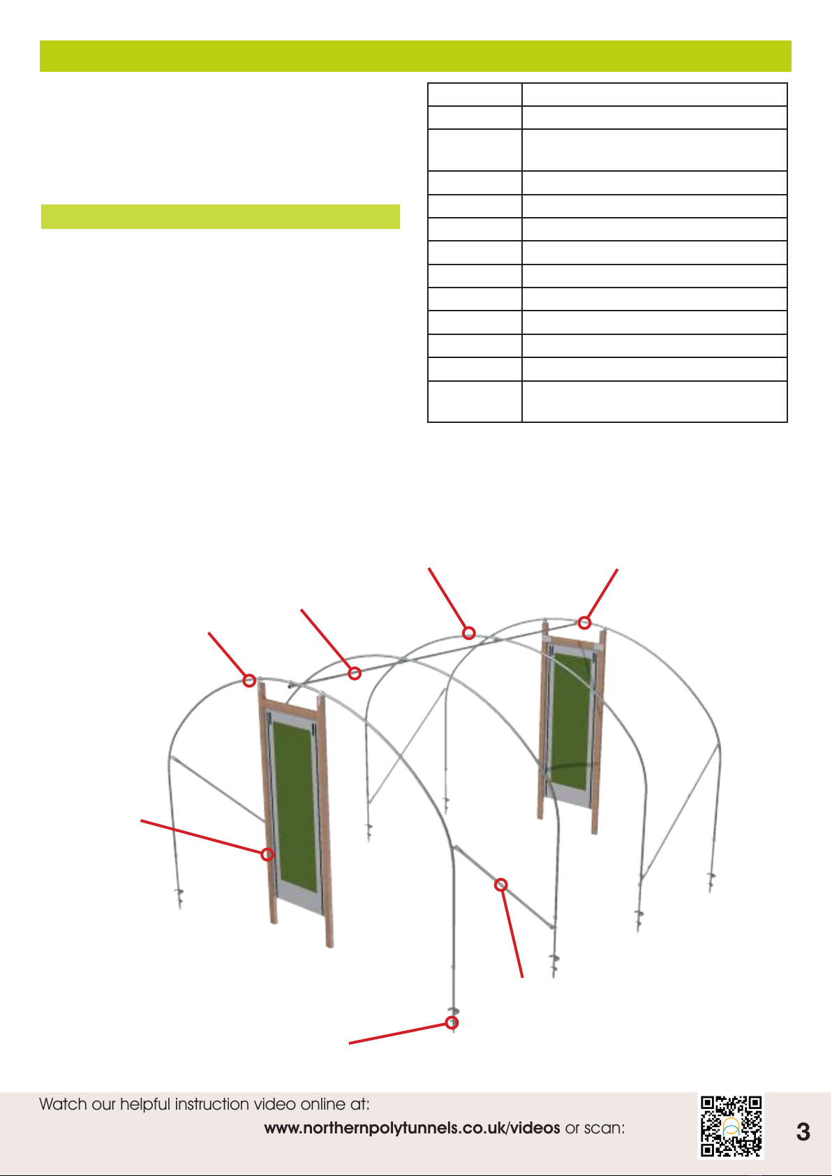
Corner Stabilisers
End Hoop
Inner Hoops
Ridge
End Hoop
Construct your polytunnel in this sequence:
Doors
Foundations
Hoops
Ridge
Corner Stabilisers
Door Frames
End Base Rail
Side Base Rail
PVC 3in1 Zip / Velcro door
Side Rail
Anti Hotspot Tape
Polythene Cover
Side Ventilation
Tightening Cover
Wooden Door Frame

45
Need any help or advice? Call: 01282 873120 or Email: [email protected] www.northernpolytunnels.co.uk/videos or scan:
Foundations - Squaring the polytunnel
Parts / Packs Foundation Tubes
Tools Tape measure, Tape, Setting out pins / pegs, String
Creating your right-angle.
1 - Take a foundation tube/screw anchor and install it in the ground where you want your front left-hand corner
to be. (facing the front door, the foundation you’ve just installed will be on the left corner) (Image 1, A)
2 – Install a second foundation tube in the ground past the length of your 3 measurements (ie, if you’re doing a
3ft length, place the foundation tube 5ft away)
3 - Take a length of string and tie it between the two foundation tubes so it’s taut. (Image 1)
4 – From the original corner foundation tube, mark 3 ft along towards the second tube. (Image 1, B) and place a
peg here.
5 – From the same original foundation (A), take a second length of string and measure 4ft by making an arc
(Image 2)
6 – From the 3ft marked measurement (B) peg, draw an arc 5ft (Image 3)
7- Where the arcs cross is your exact point for your right angle triangle. (Image 4)
8- Using the original corner foundation tube, you can now extend your string lines through the exact points
(B&C) for the rest of the foundation tubes.
9 – To double check your measurements, the diagonal measurements across the opposite corners of the
polytunnel should be the same on both sides.
We recommend that the foundations are set out accurately, this will ensure the polytunnel is constructed to satisfaction.
Use the 3:4:5
Triangle Method to position the foundation tubes correctly. This will ensure the ends are square with the sides.
Any measurement can be used, simply multiply the 3,4,5 by the same number.
e.g. – 3ft, by 4ft, by 5ft can easily be multiplied by 5 to become 15ft, 20ft, 25ft, or by 10 to be 30ft, 40ft, 50ft.
For this example, we’re going to keep it simple at 3ft, 4ft, 5ft.
Image 1 Image 2 Image 3 Image 4
BA
C

45
Need any help or advice? Call: 01282 873120 or Email: [email protected] www.northernpolytunnels.co.uk/videos or scan:
Watch our helpful instruction video online at:
45cm
35cm 35cm
exhaust
clamps
Screw Anchors
n.b. Avoid on ground with a high stone/rubble content,
peat soils, or loose ground which has been recently
disturbed or deep cultivated.
Push each of the screw anchors into the ground, just
enough so they will stay in position.
Once you have squared the polytunnel and positioned
all the screw anchors (see page 4), they can then all be
screwed into the correct depth.
Insert the ‘T’ bar through the holes at the top of the
screw anchors and turn clockwise (as you would
a corkscrew) until the required depth is achieved.
(Approx. 40-45cm remaining above ground).
Even if some of the screw anchors hit large stones -
forcing you to dig them out - you can still secure the
screw anchors in place using concrete or quick setting
postmix if required.
If you find it dicult to screw in the screw anchors, you
can use a longer T-bar or eectively extend the one
supplied by sleeving a length of steel tube over one
end of the T-bar.
Foundations - Foundation Tubes
Traditional Ground Tubes
Concreting method: For each foundation tube, dig
a 35cm wide x 45cm deep hole. Fill the hole to the
required depth with concrete or quick setting postmix.
Position each foundation tube in the concrete leaving
40-45cm above the finished ground level.
Ensure the clamp has been securely fastened to the
base of the foundation tube. This will prevent the
foundation tube from pulling out after the concrete has
set.
The exact position of the clamp is not crucial so long
as it is somewhere in the bottom half of the concrete
foundation, the nearer the bottom the better. It may be
desirable not to fill the hole completely, but to leave a
space at the top to backfill with soil. This will hide the
concrete and allow you to cultivate up to the edges of
your polytunnel.
Driven into the ground: Foundation tubes are simply
knocked in the ground, leaving 35-45cm protruding
(depending upon the ground conditions). This method
is only recommended where the polytunnel cover is
trenched into the ground.
Traditional Ground Tubes
PLEASE NOTE: Regardless of which ground tube option you have chosen the same method of squaring will
apply. It is essential that the ground tubes are fitted accurately to ensure the polytunnel is constructed to a
satisfactory standard
Make sure the ground tubes are in line and set to a constant height with their opposite ground tube.
Install each corner and run a builders string around the perimeter to aid with installing the inner ground tubes
Check that the ground tubes are at 90º to each other by measuring 3m down the length, 4m along the width
and checking the resulting measurement between the two points is 5m.

67
Need any help or advice? Call: 01282 873120 or Email: [email protected] www.northernpolytunnels.co.uk/videos or scan:
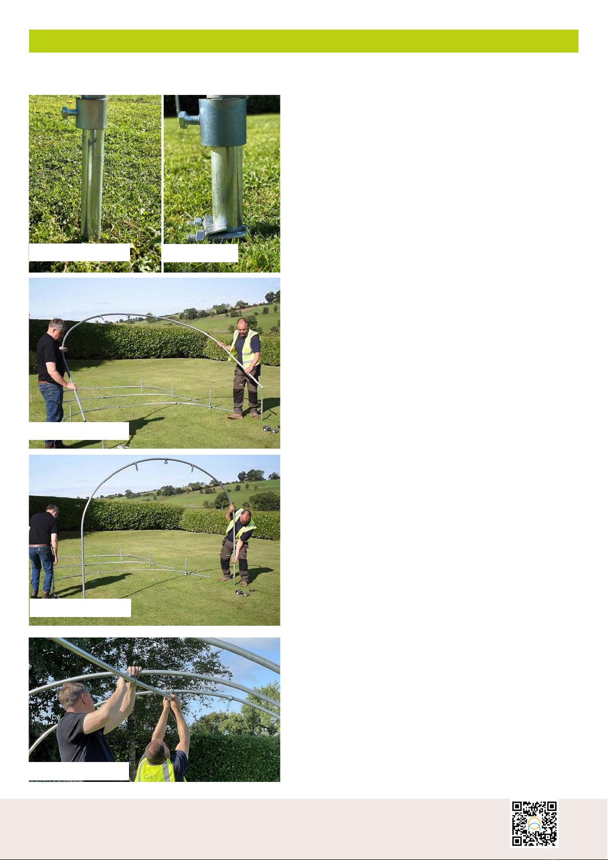
Image 1
Our hoops are supplied in two pieces, one half having a
swaged end with the other being plain.This allows the
two halves to slot together.
The 920mm long straight section on the ‘plain’ hoop
goes on the outside of the tunnel otherwise your hoops
will not have the right profile.
Step One (Image 2)
Slot your hoop pieces together and lay them out along
the length of your tunnel space next to the foundation
tubes.
Step Two (Image 3)
Take the saddle clamps from the HPK01 pack and drop
them over the foundation tubes of your first inner hoop.
Step Three(Image 4)
Now thread the hoop to ridge bracket onto your end
hoops. Make sure that the bolt heads face inwards
into the tunnel on the end hoops to prevent them from
damaging the polythene cover later. Hand tighten the
bolts so that the brackets stay in place.
Step Four (Image 5)
Next thread the door frame brackets onto your end hoop.
Make sure that the flat plate will be on the outside of the
tunnel and that there is one on either side of the hoop to
ridge bracket. Hand tighten the bolts. (Image 5).
Hoops and Ridge
Parts / Packs End Hoop Pack (HPK01), Inner Hoop pack (HPK02)
Tools 13mm Spanner / Socket
IMAGE 1
IMAGE 2
IMAGE 4
IMAGE 5
IMAGE 3
67
Need any help or advice? Call: 01282 873120 or Email: [email protected] www.northernpolytunnels.co.uk/videos or scan:
Watch our helpful instruction video online at:
Step Five (Image 6)
Place the pipe collars from HPK01 onto your corner
foundation tubes and then move on to the HPK02
inner hoop packs and place the pipe collars on the
foundations. Then thread the hoop to ridge brackets on
to the hoops as previously (step 4)
(Note that on your first inner foundations there will
already be the saddle clamps - the foundation collar will
go above these). (Image 7)
At this stage, you will have left 2 roofing bolts with nuts
and washers, EBP07 (Keyhole Clamps) and the plugs for
the ridge tube. Keep these safe!
Raise the pipe collars on the end hoop foundation tubes
to 150mm above the ground and tighten the bolts to
hold them in place. These collars enable you to raise
the hoops into the polythene cover and achieve a drum
skin-tight finish. This is done at this stage as once the
door frames are in place you won’t be able to raise the
end hoops.
Leave the intermediate hoops at ground level for now,
as they will be lifted after the polythene cover is fitted to
apply extra tension to it.
Step Six (Image 8 & 9)
Now lift the hoops and place them onto the foundation
tubes.
Step 7 (Image 10)
Now add the ridge tube to the tunnel. This comes in
sections either 5ft or 6ft long depending on the hoop
spacing chosen. One tube will be plain with the rest
being swaged at one end.
Start by slotting the plain tube into the first two hoop-
to-ridge brackets so that the end is flush with where the
end of the tunnel will be.
Then slot in the swaged sections one after another to
complete the ridge along the full length of the frame.
Tightening the bolts onto the ridge tube when it is in
place.
When you are happy you can insert the plastic plugs you
saved earlier into the two ends.
Hoops and Ridge Continued
IMAGE 6 IMAGE 7
IMAGE 9
IMAGE 8
IMAGE 10
89
Need any help or advice? Call: 01282 873120 or Email: [email protected] www.northernpolytunnels.co.uk/videos or scan:
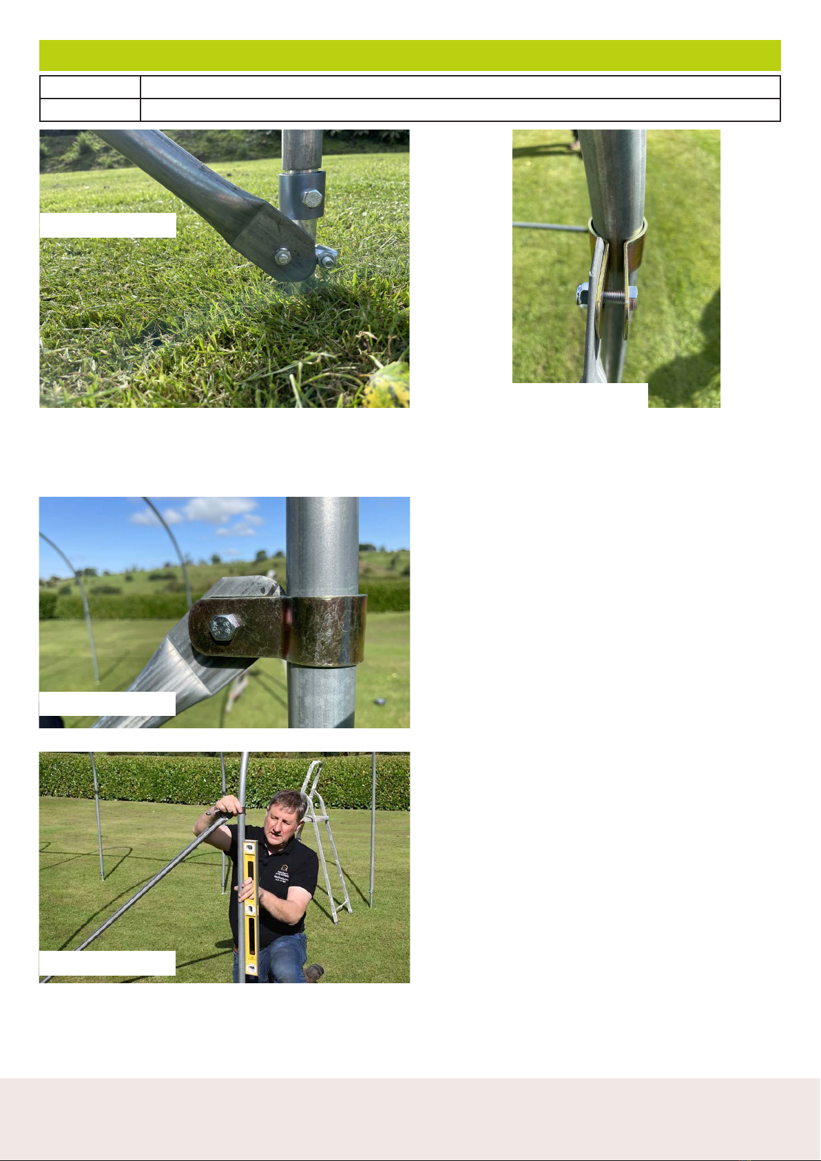
Corner Diagonals
Parts / Packs End Strut Pack (EBP07) which you saved from HPK01 earlier.
Tools 13mm Spanner/Socket, Spirit Level
There are 4 corner diagonal brace bars one for each
corner which braces the gable end and ensures that
the end hoops are plum.
The brace bars have 2 flattened ends. Remove the
nut closest to the end hoop from the saddle clamp
at the base of your first inner hoop, slot the threaded
end of the saddle clamp through the hole in the brace
bar then tighten up the nut enough to hold in place.
(Image 1)
Take the keyhole clamp, a bolt and nut from the end
strut pack. Put the keyhole clamp around your hoop
(it can be stretched and pushed back together by
hand).
Thread the bolt through from the outside of the tunnel
through the holes in the keyhole clamp then through
the hole in the flattened end of the diagonal. (Note:
do not clamp the brace bar between the opening on
the keyhole clamp as it will not tighten.) (Images 2 &
3)
Now tighten the nuts at the base of the diagonal.
Then use a spirit level and adjust the height of the
keyhole clamp on the hoop to make sure that the
hoop is straight. When you are happy tighten the
nuts to fix the keyhole clamp in the correct position.
(Image 4)
Repeat this process on each corner of your tunnel.
IMAGE 1
IMAGE 3
IMAGE 4
IMAGE 2
89
Need any help or advice? Call: 01282 873120 or Email: [email protected] www.northernpolytunnels.co.uk/videos or scan:
Watch our helpful instruction video online at:
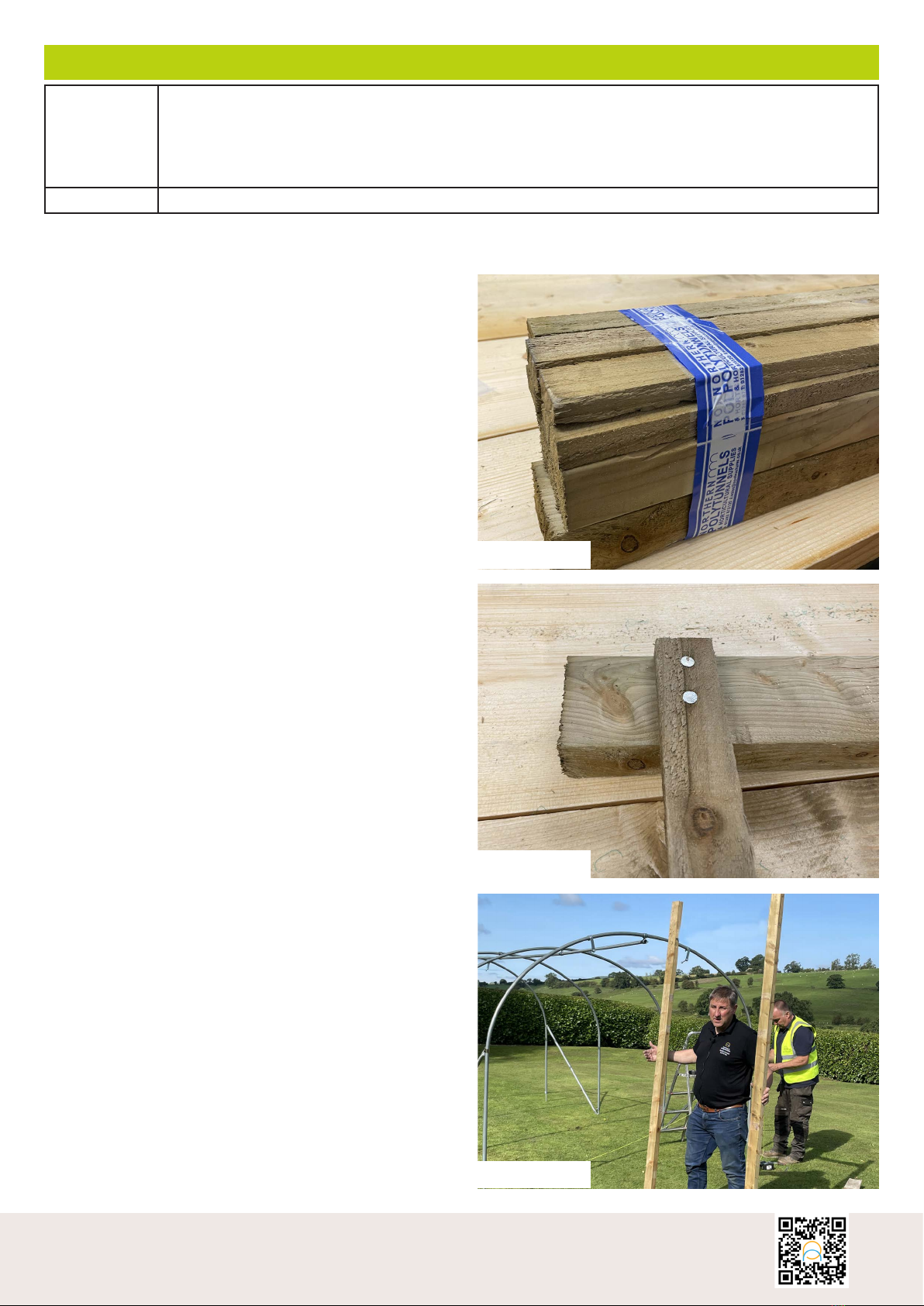
Door Frames
Parts / Packs Timber Door Frame Pack HPK07
You will also need the HPK01 - End Hoop Pack (For each end hoop)
2 x ROOFING BOLTS FOR DOOR FRAME BRACKET
2 x PLAIN NUTS
2 x WASHERS
Tools Drill, Tape Measure, Hammer
Build your door frames on a flat surface first.
The two 2.4m lengths will be the uprights and the
shorter 1.6m length will be cut to the width of your
entrance.
(Image 1)
Cut one of the timber battens to 950mm long (for a
single door)
Using 4 of the 35mm nails fix this cut batten to the base
of the door frame (flush to the outside of each upright)
at 50mm from the end of the uprights.
(Image 2)
This batten is going to be used to keep the frame at the
correct width at the base of the entrance. The inside of
the door frame should measure 800mm
Repeat this process for the other side making sure that
the uprights are square and level.
Repeat this process for the second door frame.
Your frames are now ready to be fitted into your tunnel
framework. (Image 3)
IMAGE 1
IMAGE 2
IMAGE 3

10 11
Need any help or advice? Call: 01282 873120 or Email: [email protected] www.northernpolytunnels.co.uk/videos or scan:
Fitting The Door Frame
Run a string line across the front of the tunnel from one end
of the hoop to the other to act as a guide for the door frame.
Position the door frame behind the string line then measure
accurately to make sure it is central between the two sides of
the hoop.
Use a spade to mark roughly where the ends of the door
frame are going to go.
Image 1
Dig a trench big enough to take the door frame - it needs to
be deep enough so that when the frame is set within it, the
tops of the door uprights are clear below the hoop. (Image 2)
Line up the top of the door frame with the door frame bracket
and drill a 10mm hole to fix the door frame to the bracket
using a roofing bolt provided in HPK01.
(Image 3)
The flat side of the bracket must be on the outside of the
tunnel to ensure the frame is flush with the end of the tunnel.
(Image 4)
Repeat for 2nd upright
Door Lintel
Measure the height of your door from the ground and mark
to the top of the door frame upright:
• 8, 10ft wide = 2m from ground to underside of lintel
• 12, 14, 16ft wide = 2.2m from ground to underside of lintel
for DIY Door / 2m for PVC 3in1 door
This is the location for the underside of the door lintel.
Mark the location for the centre of the lintel (37mm)
Use a 6mm drill to drill through the side of the upright where
you have marked. These holes will act as a guide when
nailing in place the door top.
Cut the 1.6m 3” by 2” timber for the door top to the required
width (800mm). Line up the centre of your door top timber
with the drilled hole, then knock a 6” nail through the hole to
join the 2 pieces together.
When you are happy that your frame is square reinforce the
joints at the door top with nails and nail plates.
Use 10 of the 35mm nails on each side of the nail plate. Fix
the nail plates to the same side of the frame as you fixed the
batten to earlier (inside). (Image 3)
Make sure that your door frame is plum once it is in place.
When you are happy backfill your trench.
Repeat on the other side
IMAGE 1
IMAGE 2
IMAGE 3
IMAGE 4 IMAGE 3
10 11
Need any help or advice? Call: 01282 873120 or Email: [email protected] www.northernpolytunnels.co.uk/videos or scan:
Watch our helpful instruction video online at:
Base Rail
Parts/Packs Hobby Corner Base Rail Bracket Pack (HPK03), Hobby Side Base Rail Bracket Pack (HPK04),
Timber Base Rail Pack (HPK05), Timber Base Rail Join Pack (HPK06)
Tools Spade
Lay the timbers for the base rail out in position around your tunnel frame. You will have four, 4ft or 5ft lengths
depending on the width of your tunnel to use on the gable ends. There will be 8ft lengths to use down the sides
and shorter lengths to make up full sides. You will need to trim these to size to suit your tunnel.
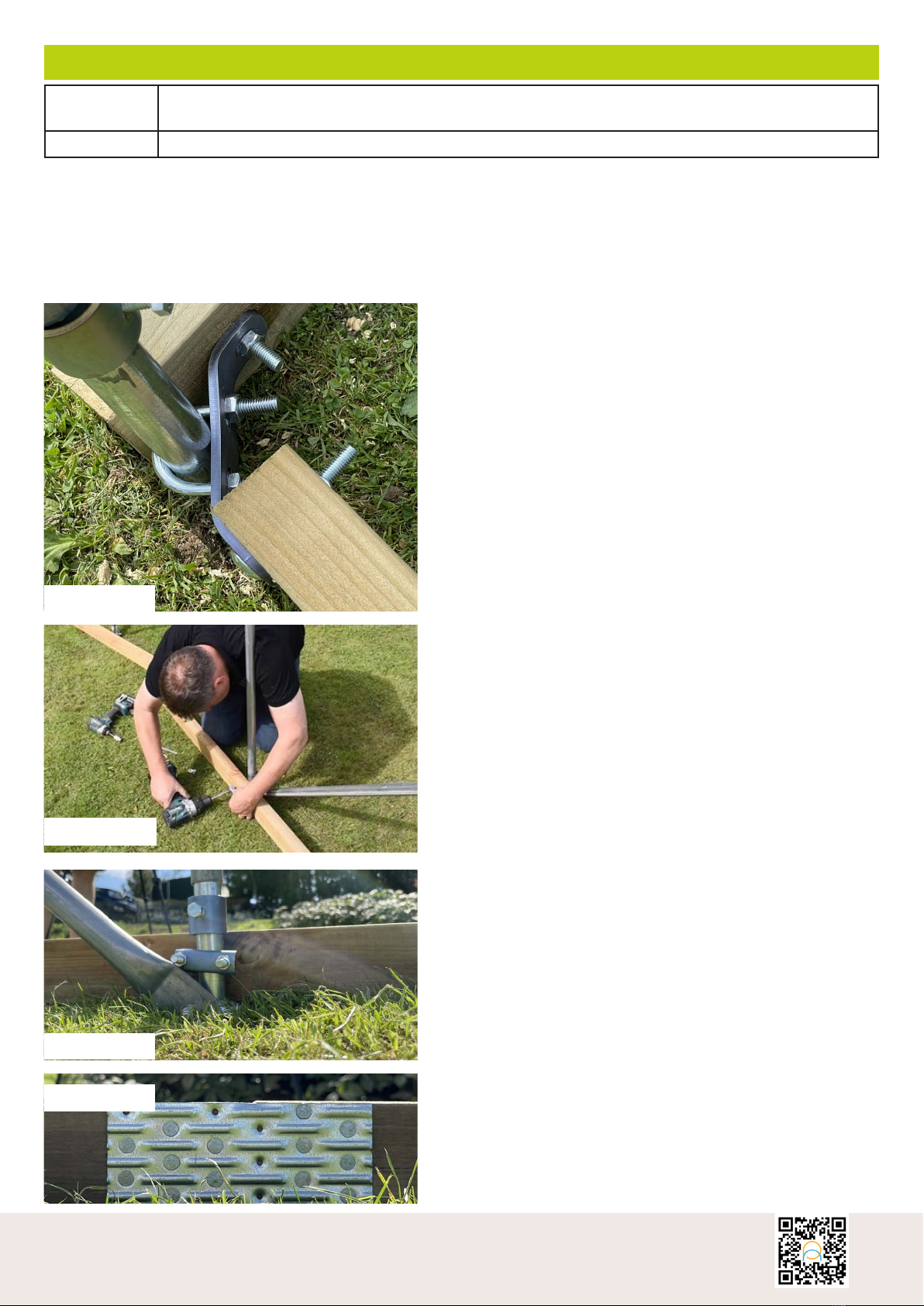
Fix the corner brackets onto the corner foundation tubes, remove the nuts. Then the U bolt wraps around the
tube and the bracket is fixed on the inside of the foundation and the nuts are then tightened enough to hold it in
place.
Now mount front base rail so that it sits flush with the front
of the door frame and the foundation tube. If the timber is
longer than the gap between the foundation tube and the
door frame mark where it meets the door frame then trim to
size.
Position your gable end timber in the right place, then using
the corner bracket as a guide, drill from outside through the
hole in the bracket and right through the timber. Slot one of
the bolts from HPK03 through the bracket and the timber
from the outside and secure with a nut.
The side rail needs to be flush with the front of the gable
end base rail. This time mark a guide hole through side rail
bracket from inside then drill right through the timber. Take
a bolt from HPK03 through the timber then the bracket and
secure with a nut.
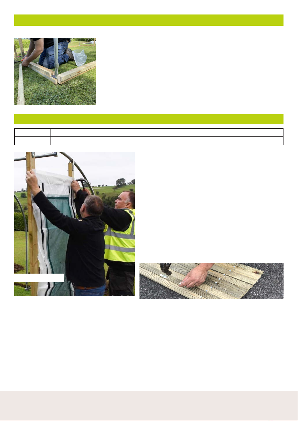
The side rails are fixed to the hoops using the intermediate
hoop brackets from HPK04.
First, make sure that the hoop tensioning collar is above the
base rail.
Mark guide holes on the timber using the collar from the
intermediate hoop bracket then drill right through the side
rail. (Image 2)
IMAGE 2 Slot the bolts through the side rail on either side of the
foundation tube, then slot on the retaining collar and
secure in place with the nuts. (Image 3)
IMAGE 3
Nail plates are used to join any joints between timber
pieces on the base rail. Position the nail plate on the
side of the base rail which will be inside the tunnel.
Use 10 nails per side of the nail plate to hold in place.
(Image 4)
Nail plates are also used to fix the gable end base rail
to the base of the door frame, use a couple of nails on
each side of the joint to hold the nail plate in place as
a start. Then use a 6” nail to reinforce the joint from
the inside of the door frame through into the base rail.
Then finish o with approximately 10 nails each side of
the joint on the nail plate.
IMAGE 4
IMAGE 2
12 13
Need any help or advice? Call: 01282 873120 or Email: [email protected] www.northernpolytunnels.co.uk/videos or scan:
The polythene is fixed to the tunnel using timber battens.
The first row of battens is nailed to the top outside face of the base rail, use
a short piece of batten as a spacer underneath the batten you are fixing.
The top batten is held in place with nails every 400mm.
Fix battens all the way around your base rail. (Image 2)
We recommend pre-nailing the battens on a flat surface, it will make it a lot
easier to fix them to your structure.
N.B. If you have not chosen the PVC Double Zip Vent Door option you will
also need to batten around the outside of your door frame.
Battens
IMAGE 2
PVC Double Zip Vent Door
Parts / Packs Double Zip Vent Door
Tools Hammer
Image 1
Position the PVC Double Zip Vent Door so that the velcro
fastenings are just under the bottom of the door top and the
Velcro panel peels o on the inside of the tunnel.
Use a nail on either side of the door frame to hold it in place.
Check the vent door is parallel to the door frame then put
2 more nails at the bottom of the door upright - keeping
tension in the vent door as you do this. Then add another 2
nails about halfway up the door uprights - one on each side.
Next - Battening - (Image 2)
Before battening, we recommend pre-nailing the battens
on a flat surface before trying to fix them to your door
frames, it will make it a lot easier to fix them to your
structure.
IMAGE 1
IMAGE 2

12 13
Need any help or advice? Call: 01282 873120 or Email: [email protected] www.northernpolytunnels.co.uk/videos or scan:
Watch our helpful instruction video online at:
Image 3 & 4
Now batten around the vent with the timber battens - these go to the outside edge of the door up-
rights and door top.
The nails are spaced at 40-45mm apart.
See the next page for the instructions on how to build your wooden door
Optional Extras – Side Vent
Parts / Packs Side Vent Pack (EBP18), Side Vent Additional Hoop Pack (EBP19)
Tools 13mm Spanner, Tape Measure, Spirit Level
If your tunnel is over 20ft long we would recommend side ventilation.
Step 1: Once your polytunnel framework has been constructed you
should attach the aluminium side vent rail.
This is normally positioned approx. 80-100cm above ground level,
below the point where the hoops start to curve.
The side vent rail is attached to each of the intermediate (inner)
hoops using the brackets provided (see image 1 & 2).
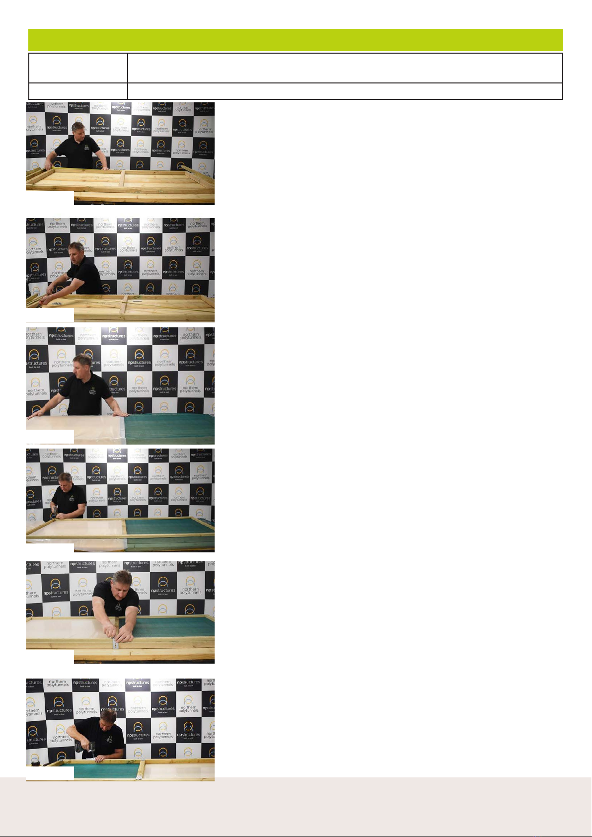
Step 2: The side rail is attached to the two end hoops using the ‘P’
clip fixings (see image 3 & 4). Ensure the side rail is straight and
that the distance from the base rail remains fairly constant along the
length of the polytunnel. This will ensure the roll-down screen sits
neatly when in the down position. If your tunnel is on a slight slope
then you can allow a slight fall on the side rail, but you will need to
make an allowance for this when attaching the roll down screen
later.
Now continue with the build (the remaining instructions for
your side vent are on page 23
IMAGE 1 IMAGE 2
IMAGE 2 IMAGE 2
PVC Double Zip Vent Door Continued
IMAGE 3 IMAGE 4
14 15
Need any help or advice? Call: 01282 873120 or Email: [email protected] www.northernpolytunnels.co.uk/videos or scan:
Parts / Packs Timber Door Frame Pack (HPK08), the Door Cladding Pack (EBP22 or 23) and Timber
Door Fittings Pack. (HPK09)
Tools Tape measure, Hammer, Drill
Wooden Hobby Door Build
Your timber pack contains;
2 x 2” by 2” timbers - 700mm long
3 x timber battens - 700mm long
2 x timber battens - 1.9m long
2 x 2” by 2” timbers - 2.2m long
Using the 2” x 2” timbers lay out the basis for your door frame.
The 700mm pieces go between the two 2.2m long pieces.
n.b. If you have an 8ft or 10ft wide tunnel, cut the 2.2m door uprights down to
2m
Mark the centre of the 2.2m long pieces as a guide for the middle piece section.
Image 1
Screw the 2” by 2” timbers together using the wood screws from the packs.
Predrill holes first so the timber doesn’t split - 2.5cm in from the ends and on
centre of the centre line marked previously. Now check that your doors are
square - the diagonal measurements should be equal! - Image 2
Once you are happy that your door is square you can fix on nail plates at each of
the joints. Now turn the door over so nail plates are on the underside.
Covering the door. Image 3
You’ll have enough polythene and netting to do either:
Full Polythene Door
Full Netted Door
Half and Half
For this example we’re using polythene on the bottom and netting on the top.
Top Tip
If you choose to put netting on the door, it’s worth keeping the extra polythene
that you don’t use for the colder months to act as a wind break.
Lay the netting out on the top panel and secure in place with a stapler making
sure the netting is nice and taught. (Hammer in any staples)
Trim o the excess netting making sure it almost fully covers the middle piece of
timber
Add the polythene on the bottom with the stapler, keeping tension as and where
you can, overlapping the netting in the middle. Image 3
Place the 700mm battens across the 3 cross pieces of the door (top, bottom,
middle). Then lay the 2 long battens on the side timbers. Use the 40mm nails to
attach the battens to the 2 x 2 - nails need to be approx 150-200mm apart. Trim
o any excess polythene and net. Image 4
Image 5 Now fix on the hinges and door latch - we recommend hinging the
doors so they open inwards into the tunnel; so they do not catch and blow o
in the wind. Decide whether you want your door to be hinged on the left or the
right-hand side. Fix the hasp and staple to the side you don’t want to hinge. Fix
the hasp in the middle near the crosspiece. Turn the door over so that the nail
plates are facing upwards.
Use the 30mm screws to fix the hinges to the door - make sure that the hinges
are square to the timber and that the butt of the screw is facing up. Image 6
Top Tip
If you have you door opening inward, make sure you place a door stop (a wedge
of wood in the ground will work) in the tunnel to avoid the door damaging the
polythene on the inside of your tunnel.
Your door is now ready required.
Image 1
Image 2
Image 3
Image 4
Image 5
Image 6
14 15
Need any help or advice? Call: 01282 873120 or Email: [email protected] www.northernpolytunnels.co.uk/videos or scan:
Watch our helpful instruction video online at:
Anti-Hotspot Tape
IMAGE 4
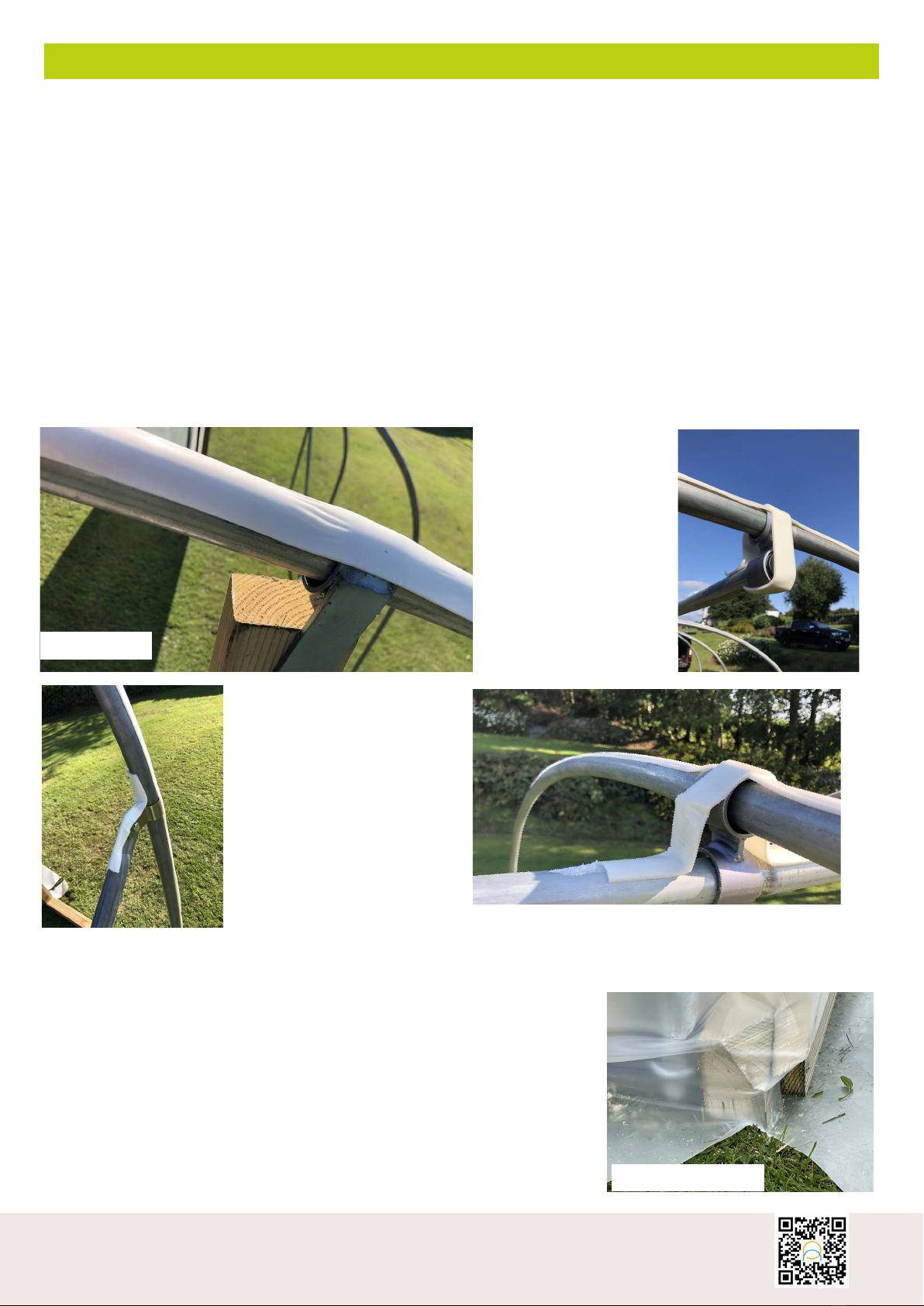
There are two widths of hot spot tape provided, 30mm and 20mm.
The wider tape is used on the end hoops as the polythene cover will have greater contact with
the end hoops, due to the polythene being pulled around the ends. The 30mm tape should be
positioned accordingly, half on the top edge of the hoops and half on the outside face of the hoop.
(Image 1)
Apply the anti-hot spot tape over the whole hoop, from ground level to ground level (or just above),
so that all parts of the hoop has the foam barrier where the polythene comes into contact with it.
This prevents any heat build-up in the steelwork from being transferred to the polythene cover and
also reduces the likelihood of the hoops rubbing against the polythene. You may want to put a little
extra anti-hot spot tape over any fittings, bolts or sharp edges that may damage the polythene.
(Images 2, 3 & 4)
IMAGE 1 IMAGE 2
IMAGE 3
Top Tip
Before covering your tunnel and to help avoid damage to your
polythene cover when you pull it tight and fasten it to the base rail, we
strongly advise that you take the time to cut o any sharp edges on
your base rails (Image 1)
IMAGE 1
16 17
Need any help or advice? Call: 01282 873120 or Email: [email protected] www.northernpolytunnels.co.uk/videos or scan:
Polytunnel Cover
Fitting the cover
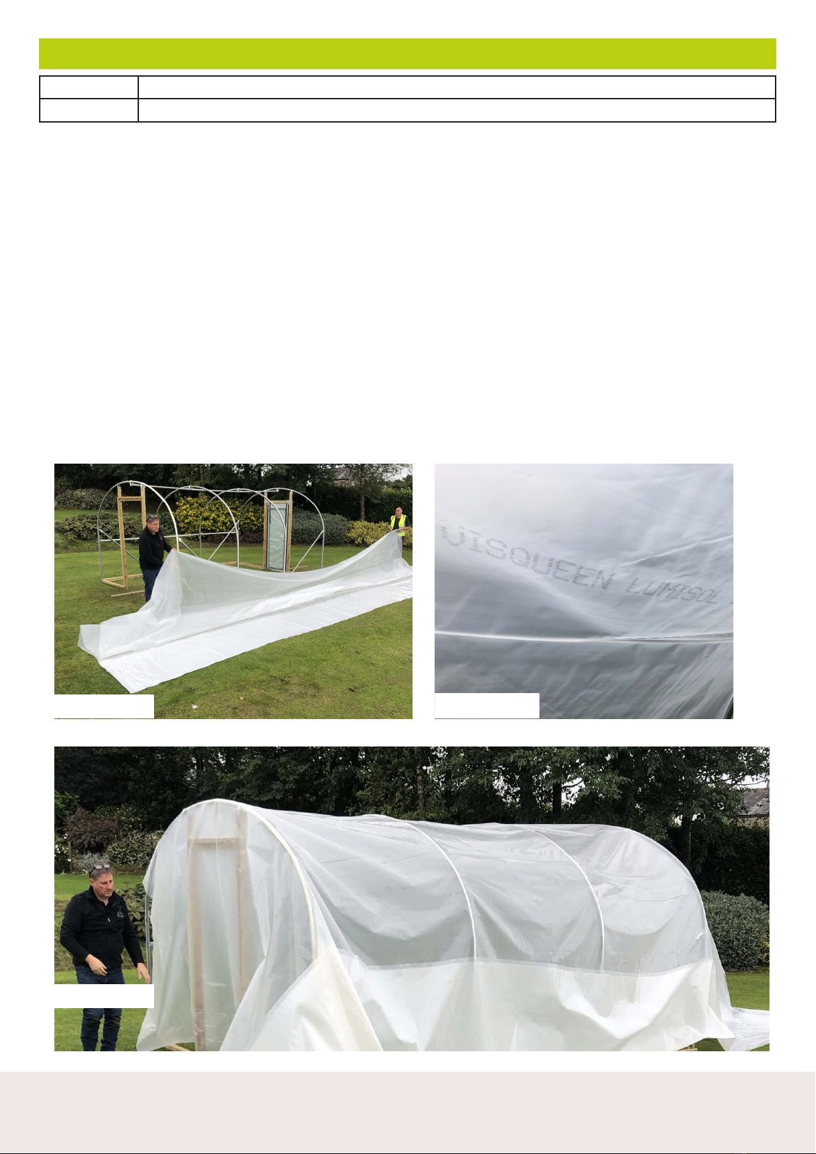
NOTE: Don’t attempt to cover the polytunnel if windy. However, if there is a slight breeze then use this to your
advantage and pull the cover over the tunnel into the breeze.
Step One
Unroll the polythene sheet along one side of your polytunnel (preferable on the downwind side if there is a
slight breeze), Image 1
Then pull the polythene cover over the polytunnel frame Image 2, allowing it to unfold as you do. Make sure
there are equal amounts of polythene, both to the ends and to the sides.
NOTE: Because our polythene has an anti-condensation additive on the underside it is important to fit your
cover the correct way up. If you stand inside the covered polytunnel you will see the words “VISQUEEN
LUMISOL” printed on the polythene (image 3).
If you can read this then you’ve installed it correctly, if not, remove and replace it.
IMAGE 1 IMAGE 3
IMAGE 2
Parts / Packs Polythene
Tools Spade, Hammer, Fork
16 17
Need any help or advice? Call: 01282 873120 or Email: [email protected] www.northernpolytunnels.co.uk/videos or scan:
Watch our helpful instruction video online at:
Polytunnel Cover – Continued
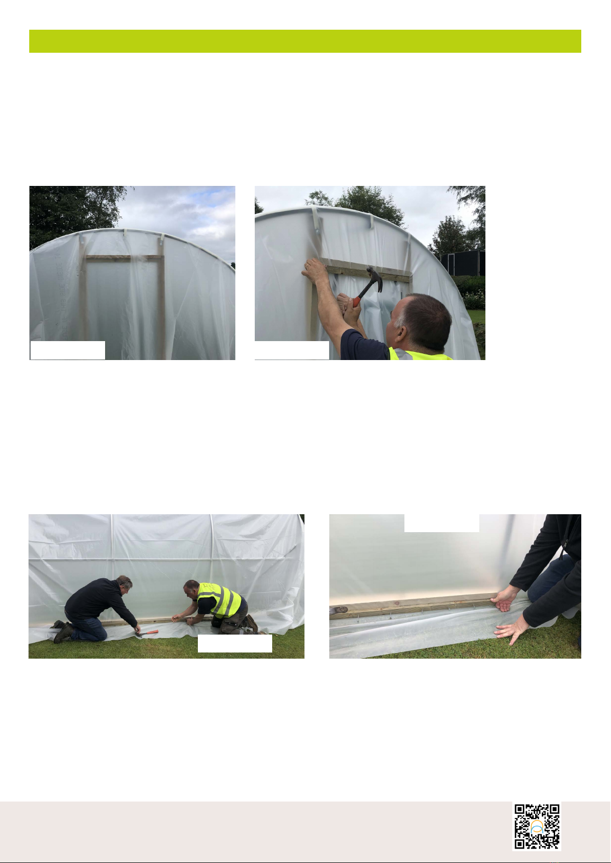
Step Two
Secure the cover at one end by pulling the polythene tight and inserting 1 of the nails on the batten in the
centre of the door frame under the existing batten. (Images 4 & 5)
Repeat this procedure on the other door frame.
Once both battens are in place pull the cover tight and fully secure the batten onto the top of the door frame
with the remaining prepared nailed batten (don’t fasten the door frame side battens yet)
IMAGE 4 IMAGE 5
Step Three
You can now start securing the polythene to the side base rails. (Image 6) Start in the middle and work your
way outwards. Depending on the length of the tunnel you may want to use multiple battens to do this, For
example, one batten for the middle, one for the left and one for the right.
Don’t pull the cover too tight. If you can see a seam in the polythene use it as a ruler, and keep the seam
straight.
Now fix the polythene to the other side, again starting from the centre and working outwards, but this time
pulling the cover tight.
IMAGE 6
IMAGE 7

18 19
Need any help or advice? Call: 01282 873120 or Email: [email protected] www.northernpolytunnels.co.uk/videos or scan:
Polytunnel Cover – Continued
Step Four
Once both sides are complete you can work your way down each of the door posts,
Image 8 - Step Four
Using a sharp knife, cut the spare polythene from the corner outwards at a 135° angle to the base rails
(approx.). This will allow the cover to be folded around the end of the polytunnel. (Image 8)
Now you can loosely attach the polythene to the end base rails up to the door posts. Make sure you pull the
polythene both downwards and in the direction of the door frame whilst nailing in place with a batten.
Once the tunnel ends have been loosely battened you can start to fully batten down the door frame flush with
the inside edges. (Image 10)
Take note of the direction in which you’re pulling the polythene, as you move. At the top of the door frame you
will mostly be pulling the polythene downwards, but as you progress down the door frame you will gradually
change direction and begin to pull the polythene mostly across. You will need to pleat the polythene in order
to trap it all. Try and make sure the pleats are facing downwards as not to hold rainwater. This will reduce the
build-up of green algae in the pleats. Once two thirds down the door frame you will be pulling across only.
(Image 11)
IMAGE 8
IMAGE 10
IMAGE 11
Once the cover is tight and battened down on both door frames, (image 12) the cover can now be fully
battened on all ends.
Ensuring the polythene is tight, secure the batten every 40-45mm and then cut away any excess polythene.
When cutting around the door, cut under the polythene onto the wooden batten to avoid cutting through
the PVC door. (Image 13)
IMAGE 12 IMAGE 13

18 19
Need any help or advice? Call: 01282 873120 or Email: [email protected] www.northernpolytunnels.co.uk/videos or scan:
Watch our helpful instruction video online at:
Polytunnel Cover - Tightening the Polythene
Once you’ve battened the door frames, trenched in the polythene, replaced the sods, cut away any excess
polythene, it’s time to tighten the polythene on the structure. Image 1 shows an un-tightened structure.
The unique feature of a Northern Polytunnel greenhouse is the ability to simply tighten the polythene (and
loosen it if required) easily.
Simply, lift the inner hoop so that the polythene is tight against it (Image 2) whilst a second person lifts and
tightens the collar in place, holding the hoop tightly. repeat this on all sides of the inner hoops (please note
the second side will be harder to lift but will ideally be lifted to the same height as the first side)
As you can see on Image 3, the dierence a drum-tight polythene looks like using our tensioning system
compared to Image 1.
Parts / Packs Polythene
Tools Spanner
IMAGE 1
IMAGE 2
IMAGE 3
20 21
Need any help or advice? Call: 01282 873120 or Email: [email protected] www.northernpolytunnels.co.uk/videos or scan:
INS 192 - 03/2020
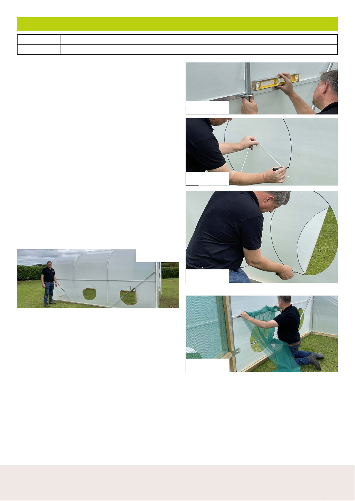
Optional Extras – Side Vent Continued
Step 1 - Now that your polythene is fully fitted and tight,
you need to make sure the Side Vent Rail is as level as
possible (if you’re building on a slope, the rail still needs
to be level so that the roll-up vent works suciently.)
To level, simply loosen the brackets where needed to
find your level. (Image 1)
Step 2 - Find the centre, to do this, measure halfway
between your hoops, make a mark with your marker
pen, and then halfway between the middle vent rail and
the base rail. Mark the middle spot on the polythene.
Now, draw a radius of around 300mm (measure 300mm
on your string, and then use that to draw a perfect
600mm circle) (Image 2)
Step 3 - Using a sharp knife, now cut out the circle
(Image 3).
Repeat on each hoop on the same side only (Image 4) (if
you’ve bought a side vent for both sides, repeat on the
other side as well)
Parts / Packs Side Vent Pack (EBP18), Side Vent Additional Hoop Pack (EBP19)
Tools 13mm Spanner, Tape Measure, Spirit Level, Marker Pen, String, Sharp Knife
Step 4 - Tuck the netting behind the side vent rail (this
will be secured on the opposite side shortly) Making
sure it’s central with roughly 30mm overhanging. The
bottom section will be battened to the base rail ONCE
the top has been secured (Image 5).
Trim o the netting just below the wooden base rail.
(Bear in mind that you’ll need to use this netting for ALL
of your vents)
Top Tip - Use scissors for cutting the netting to give a
better finish
Repeat on all sections of the side vent.
IMAGE 1
IMAGE 2
IMAGE 3
IMAGE 4
IMAGE 5
Other northern polytunnels Greenhouse Kit manuals

Popular Greenhouse Kit manuals by other brands


GREEN PROTECT
GREEN PROTECT 28105 Assembly instructions

Alton
Alton Evolution octagonal instruction manual

Elite Greenhouses
Elite Greenhouses 6'5" WIDE TITAN Instructions & Illustrations

Halls
Halls Magnum 108 manual

Gazebo penguin
Gazebo penguin W1207-32 Assembly instructions

GREEN LAND
GREEN LAND Galea 7,5 m2 manual