Northern Telecom DNC-50 User manual

450-1011-201
Network Operations Systems
DNC-50, DNC-100,
DNC-500
Dynamic Network Control
Systems
Installation Guide for Cabinet Systems
Release: NSR27/28 03 Status: Standard


i
Practice 450-1011-201
Network Operations Systems
DNC-50, DNC-100, DNC-500*
Dynamic Network Control Systems
Installation Guide for Cabinet Systems
Publication number: 450-1011-201
Product release: NSR 27/28 03
Document release: Standard
Date: March 30, 1990
1990 Northern Telecom
* DNC-50, DNC-100 and DNC-500 are trademarks of Northern Telecom.

ii
Practice 450-1011-201
Revision History
March 30, 1990 Release NSR27/28 03
Table 15-B, ALIU Options Settings, has been revised to include Alarm Output
Options.
January 24, 1990Release NSR27/28 02
The section "Installing the LAN Interface Unit" has been revised to include a
caution message about the proper connection of power to the LIU.
Preface and back pages are revised to show the reissue date, and two blank
preface pages have been removed.
November 10, 1989
Release NSR27/28 01.
This issue applies to both NSR27 and NSR28. It is reissued in its entirety
because editing has resulted in paging changes.
Procedures for cleaning and operating the Cartridge Tape Drive were
expanded to include the tape drive in the 1/4-wide tape SRU. It has a different
orientation than the tape drive in the mass storage SRUs. These procedures are
in Part 13.
May 12, 1989 Release NSR27 02.
This issue of the NTP is converted to a new document style.
Part 8 of this version contains more detailed instructions on cabling for SCSI
file systems.

iii
Practice 450-1011-201
Table of Contents
Revision History ii
Table of Contents iii
1. Introduction 1
Document Release Information 1
How to Use this Document 2
A Summary of System Installation 2
Getting Ready 3
2. Preparing the Floor Area for the Cabinets 5
3. Unpacking and Inspecting the Equipment 9
Checking the Packing Lists 9
Unpacking the Cabinets 11
Unpacking the Shared Resource Units 12
Unpacking the Line Cards for the Analog Link SRU 13
4. Installing the Cabinets 15
Installing Cabinets in a New System 16
Installing the Cabinet Jumper Assemblies 21
Installing the Horizontal Jumper Assembly 23
Installing the Input Jumper Assembly 23
Installing the Terminating Jumper Assembly 27
Installing the Rear Doors and Fan Covers for the Cabinets 29
Adding a Cabinet to an Existing System 32
5. Setting the NT4G19EA Power Supply for 115 or
220 Vac Operation 35
Setting the Voltage Option on the Power Supply SRU 36
6. Installing/Removing the Shared Resource Units 39
Installing the Loft Power Supply 40
Installing the Capacitor Interlocks (NT4G19EA Power Supply) 42
Installing the SRUs 44
Installing and Removing the EMI Covers 47

iv Table of Contents
Practice 450-1011-201
Installing the Analog Line Cards 50
Removing an SRU from a Cabinet 52
Restarting the System after the Removal of an SRU 53
7. Installing the Cross-connect Panel 55
About the Cross-connect Panel 55
Before Making Cross-connections 55
Unpacking the Office Cross-connect Panel 59
How to Install the Office Cross-connect Panel 59
8. Connecting/Disconnecting the Cables at the
Cabinets 63
Cabling for a SCSI Cluster 66
Cabling for Systems Using SASI Connections 69
SASI Cabling (Primary Processor to 80 Megabyte Storage SRU) 69
SASI Cabling for the 350 Megabyte Mass Storage SRU 72
Direct RS-232-C Connections 73
LANlink Connections to the Cross-connect Panel 75
Digital Trunk Link Connections to the Cross-connect Panel 78
Analog Link Connections to the Cross-connect Panel 82
9. Cross-connections to Distribution Frames and
Building 87
How to Use the QTBIX16A Connection Tool 89
How to Terminate Building Wiring at the Cross-connect Panel 91
10. Connecting the Meridian M4000 Terminals 93
Connecting the Headset Accoustic Limiter 96
11. Connecting the LAN Interface Units to the
System 99
Installing the LAN Interface Unit 100
Connecting an LIU to the System 102
Removing an LIU from Service 102
12. Connecting Peripherals, Hosts, and Modems to
the LIU 103
Connecting a Modem to an LIU 104
Connecting an ASCII Terminal to an LIU 104
Connecting a Serial Printer to an LIU 106
Connecting a Host Computer to an LIU 106
Connecting a Nine-track Magnetic Tape Unit to an LIU (SASI Version) 107
13. Using the Cartridge Tape Drive 113
Cleaning the Tape Heads 114
Inserting the Tape Cartridge into the Mass Storage or Cartridge Tape SRU
116

Table of Contents v
Practice 450-1011-201
Inserting the Tape Cartridge into the 1/4-shelf Disk/Tape SRU 117
Removing a Tape 118
Retensioning a Tape 119
14. Powering Up the System 121
15. Installing the Alarm System 123
16. How to Connectorize Cables 133
Connectorization Using the MI-1 Tool 133
Connectorization of DS1 Cables (CERTI-CRIMP) 135
17. Installing a -48 Vdc Power Distribution System 141
Installing a Factory-configured -48 V Power System 141
Installing the Cabinet Downgrade Kit (NT4G13AT) 150
Downgrade from Eight to Seven Cabinets 150
Downgrade from Seven to Six Cabinets 152
Downgrade from Six to Five Cabinets 152
Downgrade from Five to Four Cabinets 153
Downgrade from Four to Three Cabinets 155
Downgrade from Three to Two Cabinets 156
Installing Upgrade Kit NT4G13AU (From Two to Three Cabinets) 156
Installing Upgrade Kit NT4G13AV (From Three to Four Cabinets) 157
Installing Upgrade Kit NT4G13AW (From Four to Five Cabinets) 159
Installing Upgrade Kit NT4G13AX (From Five to Six Cabinets) 162
Installing Upgrade Kit NT4G13AY (From Six to Seven Cabinets) 163
Installing Upgrade Kit NT4G13AZ (From Seven to Eight Cabinets) 165


1
Practice 450-1011-201
1. Introduction
This document provides detailed installation instructions for cabinet-based
DNC-50, DNC-100 and DNC-500 Dynamic Network Control Systems. (For
rack-mounted systems, see the Installation Guide for Bay Systems,
450-1011-202.)
This document assumes that you are familiar with the equipment and are
trained in telephony installation tasks. It also assumes that the system
equipment has been delivered and all pre-installation planning and wiring
tasks have been completed according to the Installation Planning Guide,
450-1011-200.
Document Release Information
The release information for this issue of this document is found on page 1.
The information includes the 10-digit identification number for the practice,
plus the following additional information:
(a) Date: This is the date the document was released for reproduction or
printing. It is not intended to be the same as the software or product
release date.
(b) Product release: This is the software or product release number
associated with the current issue of the document, plus the issue number
of document. The format is NSRaa bb, where:
•NSRaa is the Network Software Release number
•bb is a sequential issue number for the document that indicates how
many times the document has been released with the specified
software release.
(c) Document release: A rating code of Draft, Preliminary, or Standard is
assigned to the document, reflecting the current status of the document.

2 Introduction
Practice 450-1011-201
How to Use this Document
This document consists of a number of parts. Each part is designed to help
you install a particular type of equipment or to perform a specific installation
task. Figures are provided with the step-by-step procedures.
A Summary of System Installation
The system is easily installed. The system cabinets are shipped fully
assembled with all necessary components built in, except for the modular
shared resource units (SRUs). Cable connections are fully connectorized or
can be connectorized in the field at the customer's option.
Installation involves unpacking and positioning the cabinets, then
interconnecting and leveling them. The SRUs are then inserted into their
preassigned positions. Finally, the various cabling connections are made.
Most cabling connections are made to a standardized office cross-connect
panel. It is assumed that the panel has been ordered and installed prior to
system installation day. If not, ensure that it is installed according to Part 7.
(Further pre-installation wiring instructions are available in NTP
555-3001-215, which can be ordered with the office cross-connect panel or
separately.)
The pre-installation wiring contractor should have already made all wiring
changes and additions, including jumpering between the cross-connect panel
and the main distribution frame.
Some equipment, such as modem pools, may require special installation
procedures. In such cases, refer to the manufacturer's documentation for
special instructions. Also, there may be special environmental, electrical, or
space requirements for equipment not supplied by Northern Telecom. Again,
refer to the manufacturer's documentation for details.
The installation process follows this sequence, of which each step is detailed
in a subsequent part of this installation guide:
(1) Prepare the floor area for the cabinets.
(2) Unpack the cabinets and position them in the designated area.
(3) Line up the cabinets, leveling and interconnecting them.
(4) Unpack and install the SRUs in their assigned positions according to the
cabinet provisioning worksheet in the Site Records, 450-1011-152.
(5) Make cable connections as outlined in the wiring logs in the Site
Records, 450-1011-152. This worksheet is located in the section titled
‘Wiring Log’. If applicable to your system, install the Alarm Interface
Unit (per Part 15), connectorize cables for nonstandard cable lengths
(per Part 16), and install the -48 V power system (per Part 17).

Introduction 3
Practice 450-1011-201
(6) Install the peripheral and external equipment according to the floor plan
and wiring logs.
(7) When all connections have been made and verified, initialize the system
according to the instructions in the Guide to DNC Base Software
Installation, 450-1011-302. (That document is available to authorized
system installers.)
Getting Ready
Before unpacking and installing the equipment, you should ensure that you
have on hand the completed worksheets and forms from the Site Records,
450-1011-152. Also included in theSite Records are the hardcopy record of
the assigned shelf positions of the SRUs and a detailed floor plan for the site.
All connections and the equipment layout should conform to the worksheets in
the Site Records.
In addition, you should ensure that all the tools, equipment, and materials
required for installing the system are on hand. All the items required are listed
here for your convenience; the specific items required for any given
procedure are listed again at the beginning of the procedure.
TOOLS:
1 Chalk line
1 Truck dolly
1 Knife
1 Small wire cutter for plastic tie-wraps
1 Carpenter's level
1 Hexagonal nutdriver (1/4 inches)
1 Hexagonal nutdriver (3/8 inches)
1 Hexagonal nutdriver (3/16 inches)
1 Allen wrench (5/64 inches)
1 Small flat-blade screwdriver
1 Medium Phillips screwdriver
1 Wire-wrap tool

4 Introduction
Practice 450-1011-201
1 QTBIX16A connection tool *
1 Measuring tape.
MATERIALS:
1 Roll of adhesive tape, durex acetate fiber
1 Felt pen
1 Pencil.
*This item is available from Northern Telecom. See your NT sales representative.

5
Practice 450-1011-201
2. Preparing the Floor Area for the
Cabinets
Before unpacking the cabinets, you must ensure that the installation area is
prepared for the equipment. You should have at hand the floor plan, which is
found in the Site Records, 450-1011-152, in the section labelled ‘Floor Plan’,
and the following tools and materials:
TOOLS:
1 Small wire cutter for plastic tie-wraps
1 Chalk Line.
MATERIALS:
1 Roll of Adhesive Tape, Durex Acetate Fiber
1 Felt Pen.
Preparing the Floor Surface. The floor surface should be firm and
unyielding, such as tile or wood covering, or low-pile carpet. This ensures
the stability of the cabinets and minimizes stress on cabinet interconnection
assemblies.
The floor must also be clean and free of any surface irregularities that might
affect the leveling of cabinets.

6` Preparing the Floor Area for the Cabinets
Practice 450-1011-201
Marking the Floor for the Cabinets. The floor should be marked with
the outline of the cabinets to facilitate their line-up and leveling. This can be
done with masking tape and a marker. Refer to the floor plan in the Site
Records, 450-1011-152.
You should use existing permanent structures such as walls or electrical
outlets as reference points. You can then set out the outline of the cabinets
using the masking tape as follows:
(1) Mark the floor with adhesive tape strips outlining the front-of-cabinet
line, as shown in Fig. 2-1.
(2) Use the chalk line to draw a distinct front-of-cabinet line on the
adhesive tape. This is to ensure the cabinet lineup is perfectly straight.
You can mark over the chalk line with a marker to make it clearer.
(3) Similarly, use the tape, chalk line, and marker to outline the sides of
each cabinet. Allow 9 mm (3/8 inches) between cabinets. A maximum of
eight cabinets can be installed in the same lineup.
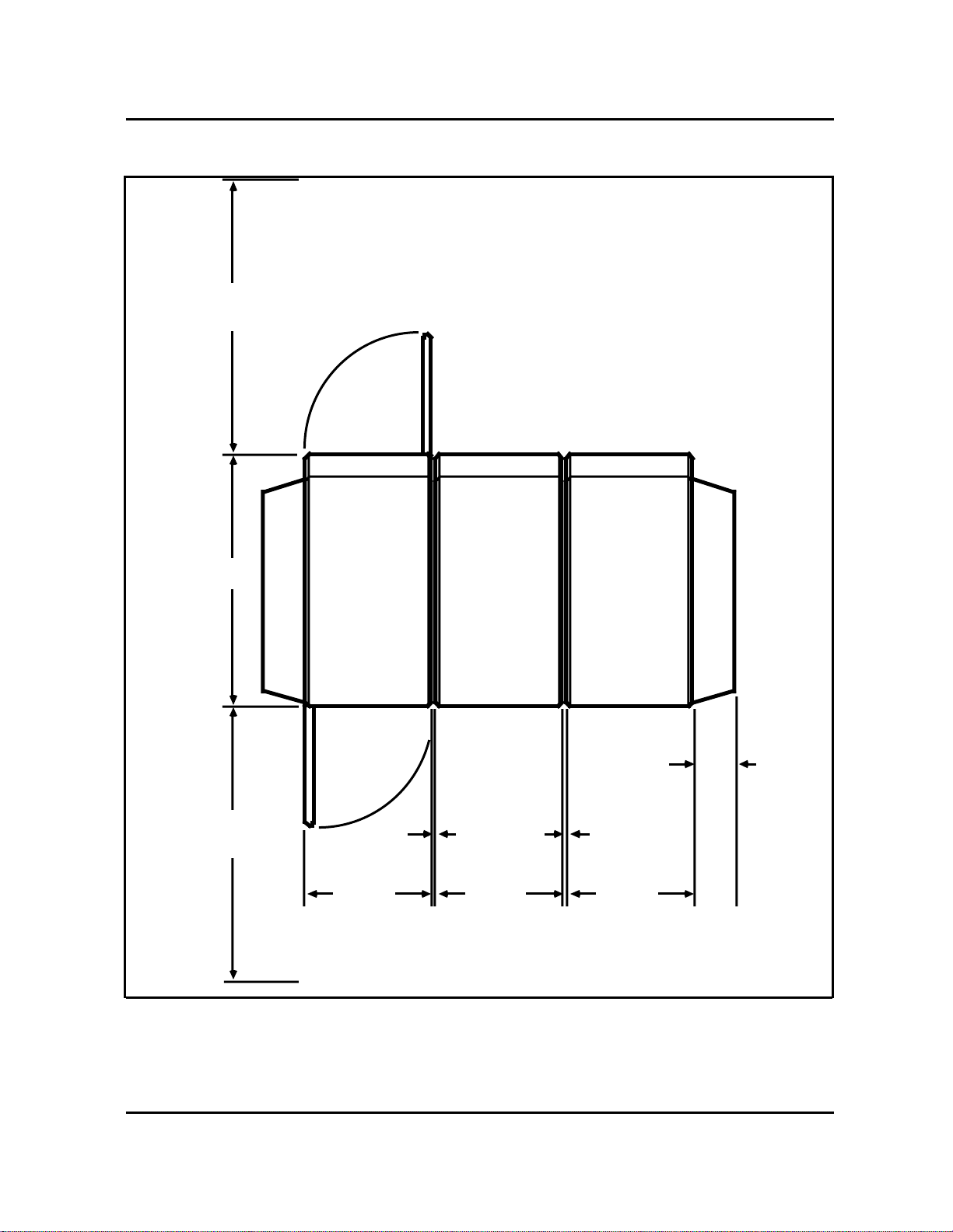
Figure 2-1
Marking the Floor for the Cabinet Lineup
Cabinet 1 Cabinet 2 Cabinet 3 Cabinet 4 Cabinet 5 Cabinet 6 Cabinet 7 Cabinet 8
Masking Tape
450-0044
560 mm
(22 in.)
280 mm
(11 in.) 10 mm (.375 in.)
Front of Cabinet Line
(Set chalkline on
masking tape)
(Top View of Cabinet)
Preparing the Floor Area for the Cabinets 7
Practice 450-1011-201
Figure 2-2
Space Requirements for the Cabinets
FRONT
Front Door
285 mm
(11.0 in.)
Allow
9.5 mm
(3/8 in.)
Allow
610 mm
(24 in.)
285 mm
(11.0 in.) 285 mm
(11.0 in.)
Allow
9.5 mm
(3/8 in.)
90 mm
(3.5 in.)
Allow
610 mm
(24 in.)
560 mm
(22 in.)
Rear Door
REAR
TOP VIEW
450-0041


9
Practice 450-1011-201
3. Unpacking and Inspecting the
Equipment
Before Starting. All system equipment is packed for maximum protection
against damage during shipment. However, inspect the shipping containers
for evidence of damage when receiving the equipment. Report any damage to
the transportation company immediately.
Next, check the shipping containers against the packing list provided with the
delivery. Report any discrepencies immediately to the transportation company.
Two people are required to move the equipment cabinets. The following tools
and materials are required to unpack the equipment:
TOOLS:
1 Truck dolly
1 Sharp knife.
Checking the Packing Lists
There are three types of cartons shipped with cabinet systems. The cartons
contain, respectively, the cabinets, the shared resource units (SRUs), and the
cabinet accessories, as shown in Fig. 3-1. Once the cartons have been moved
to the installation area and inspected for damage, the contents should be
checked against the packing list.
Note: If a component requires hardware such as screws or
mounting brackets, the hardware is taped to the component itself.
Cabinets have metal connector covers tie-wrapped to the inside shelf
frames. These covers provide protection from electromagnetic
interference (EMI) when the connector is not in use.
To identify the contents of the packing containers without opening the
containers, locate the Product Engineering Code (PEC), or part number, on the
outside of the carton and check it against the packing list.

10 Unpacking and Inspecting the Equipment
Practice 450-1011-201
Figure 3-1
Unpacking the Equipment
450-0046
Packing Material
Packing Material
Carton containing cabinet
Carton containing SRUs
Cartons containing jumper assemblies,
feet, AC power cable, cabinet interlocks,
rear doors, fan grills, and plastic air flow
slot covers.

Unpacking and Inspecting the Equipment 11
Practice 450-1011-201
Unpacking the Cabinets
- CAUTION -
The system cabinets contain electronic equipment that is sensitive to
electrostatic discharge and rough handling. Avoid any undue stress,
electrostatic discharge, shock, or vibration when handling, moving,
and unpacking the cabinets. Do not touch the backplane connectors.
(1) With the assistance of another person, move the cabinets and other
equipment in their shipping cartons to the installation area using the
truck dolly.
Note: Rear doors, interconnection assemblies, hardware, and
shared resource units (SRUs) are shipped in separate containers as
shown in Fig. 3-1.
(2) Cut open one side of the cabinet container with the knife.
- WARNING -
Be careful when handling the cabinet so that you do not injure
yourself on the sharp alignment pins on the rear of the cabinet.
These pins are used to align the jumper assemblies.
- CAUTION -
Do not grip the front door assembly or the cabinet's internal
components. Doing so may misalign the backplane and cause
operating faults.
(3) Grasp the sides of the cabinet and gently slide it out of the carton. A
second person may assist in removing the carton.
(4) Remove the foam packing material from the top and back of the cabinet.
(5) Repeat Steps 2 to 4 for each cabinet.
(6) Store all packing materials in the event the equipment has to be returned
or moved to another site.
(7) Inspect the cabinets for the following:
•damaged connectors or connectors containing foreign material
•defects in the molded plastic housing
•any obvious signs of damage to the cabinet.
(8) Open the cartons containing the rear doors, fan grills and slot covers,
the ac power cable, jumper assemblies, and cabinet feet. Remove the

12 Unpacking and Inspecting the Equipment
Practice 450-1011-201
contents and inspect them for damage. Report any damage to the
transportation company immediately.
Unpacking the Shared Resource Units
- CAUTION -
The SRUs are sophisticated electronic devices that are sensitive to
electrostatic discharge and rough handling. Avoid any undue stress,
electrostatic discharge, shock, or vibration when handling, moving,
and unpacking the SRUs.
(1) Open the shipping cartons.
(2) Using appropriate handling precautions for electrostatic discharge,
remove the SRUs from their cartons and inspect them for any obvious
signs of damage.
- CAUTION -
Do not touch the SRU connectors.
(3) For each Applications Processor SRU, record the information on the
worksheet for the SRU in the Site Records, 450-1011-152. (These
worksheets are kept in Part 10 of the Site Records.) Record the
following information:
•software license number (and revision code if required)
•SRU serial number.
(4) Place the SRUs in their shipping cartons until they are required for
installation into their allotted shelf positions.
Other manuals for DNC-50
1
This manual suits for next models
2
Table of contents
Other Northern Telecom Telephone System manuals

Popular Telephone System manuals by other brands


Teleco
Teleco Perfect Voice Tis 16 installation manual

TransTel Communications
TransTel Communications TD-824i Installation and programming manual

Nortel
Nortel BCM50 Installation and maintenance guide

Panasonic
Panasonic KX-TS25B user guide

Tynetec
Tynetec Advent xt user guide

Karel
Karel MS26S Easy to use owner's guide