Northwest Manufacturing Powertow Supertow I Owner's manual

™
Brought to you by: Powertow ™
Supertow III … Division of Northwest Manufacturing, Inc.
Pilot’s Operating Handbook
10179 N. Navion Dr., Hayden, ID 83835 - 208-635-5352 FAX 208-635-5251

Model: SUPERTOW I, II,III
Things to know:
Keep your crate in the event there is any shipping damage to your unit.
Read this instruction manual thoroughly before attempting to load
and move your aircraft.
Your unit will need Oil & Gas - before test running the unit.
Tools handy for final assembly
½” End Wrench
Phillips Screwdriver
Wire Cutters
Thank you for choosing a Powertow, for your hangaring needs.
Customer Service is #1with our company. If you have any questions
or comments on your unit, please call us at 800-635-5565
Supertow III Setup
Handle and four cables to hook up, it’s that simple. Have a friend help you with the handle.
Pre Set-Up …Keep unit on pallet for ease of assembly.
Remove the three black bolts from frame. Located at back of frame top and bottom and set aside.
DO NOT REMOVE THE MASKING TAPE from any cables, until they have been attached.
The tape in all instances is to keep the proper pre-set adjustments in place until hook-up.
Step 1 –Lever - Before attaching the handle…
.
Step 2 - Shift Cable Attachment – Short Black Cable –Remove one nut & washer. Feed end of cable
through the upright support and attach washer and nut tightly with a Crescent Wrench. Remove tape.
.
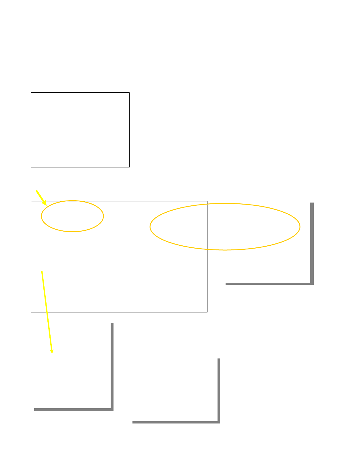
IMPORTANT – Feed the long black cable under the wire
harness going to the engine. Let it continue under engine to front
of machine and let hang loosely for now. You can then attach the
main handle using the three black bolts. Start with the top bolt
loosely: then the bottom bolts and tighten in the same order.
Wrench is supplied to tighten bolts into threaded frame
Attach end of shift cable by
pulling back outer sleeve and slip
on to the transmission shifter
Step 3 – Brake Cable Locate cable from brake handle at top of
machine. Follow down to spring end. Line up the slots in brass fitting
in order to slip wire into bracket. Pull back the spring over the cable
and slip wire into lined up slots on support. Turn slots to keep in place
Attach the other end of the
spring clip onto transmission
brake lever. Use the 1/4” bolt
from brake lever and secure
with nut – leave room for clip
to move freely.

Supertow III Setup
Step 4
Step 5 –Throttle Cable
Step 6 -Clutch Cable
Locate Clutch Cable Attached on bottom
of frame, hanging loose with black barrel.
Connect this end of Clutch Cable up to the
top half of cable with threaded end.
Run threaded end into barrel snug against
nut. This will leave most of the screw
portion showing.Remove tape.
This barrel twist chamber adjusts the
tension of the clutch.
It’s important for the clutch to fully disengage when released. If you have this adjustment too tight, the
machine will continue to travel even when the handle is released.
“Lazy Susan” Cradle
The long black cable hooks up to the
load and release plate for the Lazy
Susan Cradle at the front end of unit.
Follow same attachment procedures as
shift cable hook-ups.
Locate the throttle control
attached to the engine and
bring it up to top of
handle. Remove the two
Phillips Screws on side of
handle and install throttle
control.
The cable will be secured
down the left side with
Nylon Ties in final step.
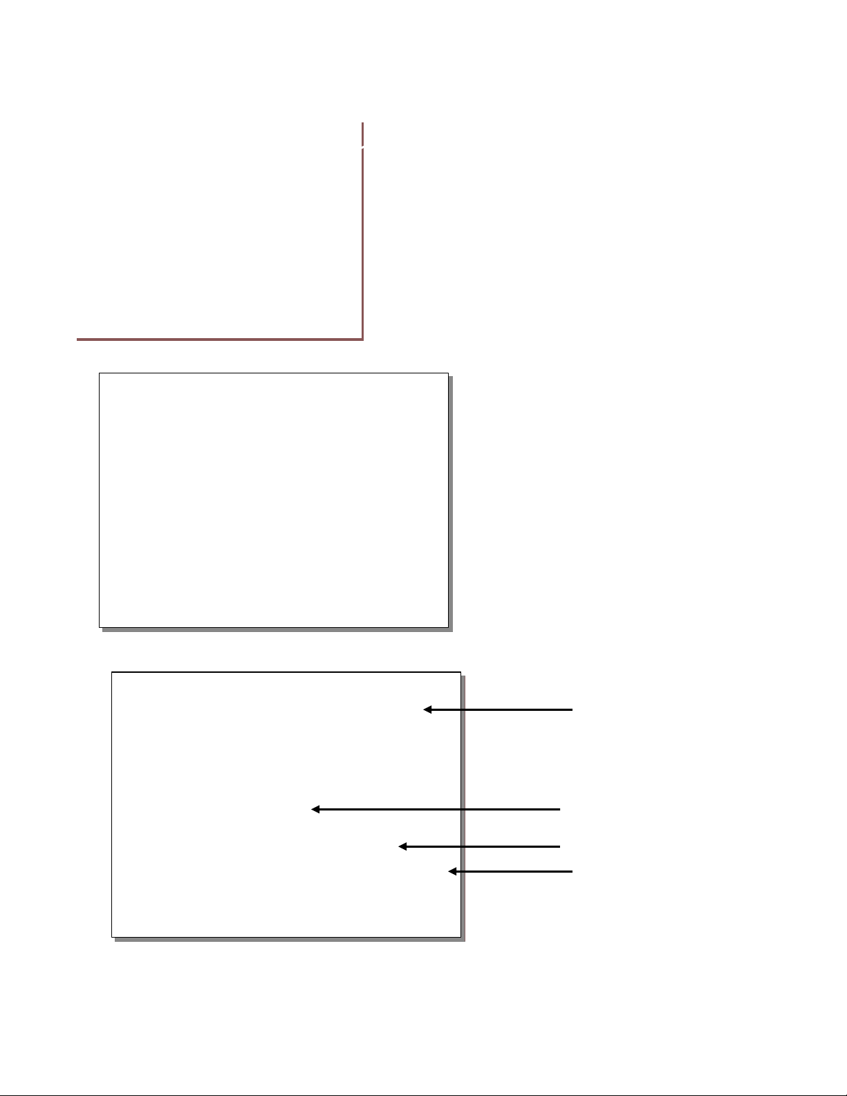
Supertow III Setup
Shift Cable
Lazy Susan
Release Cable
Throttle Control
Clutch Cable
Secure Clutch Cable to Handle.
Locate keeper on lower left side of handle. Remove the
10-24 Screw and attach Clutch Cable using the tab on
cable housing.
Be sure Clutch Cable is on the outside of Throttle and
Brake Cables, then secure all cables (Except Clutch) to
handle with nylon ties provided with Throttle Cable down
left side and Brake Cable under handle.
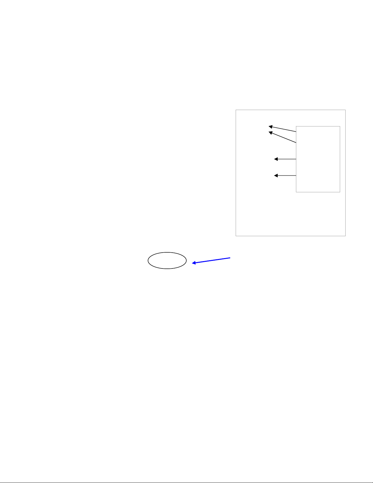
Bottom View for Reference
The two bolts next to the engine pulley are belt
guides, that create a loop around the pulley
keeping the drive belt from engaging while the
engine is running and clutch is disengaged.
There are three pulleys on the bottom of the
unit: The engine drive pulley, the large
transmission and the small clutch pulley on the
clutch arm. These pulleys need to be line
with each other. The bolt on the left side of
Clutch Arm will need to be adjusted after the
first couple hours of use. If the Clutch Arm
drops down out of alignment, it will run on the
rim of the idler pulley and spin the drive belt
off the unit.

SUPERTOW™part of the POWERTOW™ line by NW MFG
SHORT & SWEET PLEASE READ
Congratulations on your purchase of the Supertow.
As you already know, it’s a unique machine.
So let’s familiarize you with your new toy!
What’s where…?
Let’s start by standing at the rear of your tow.
On the handle, above the throttle are two lever handles.
Transmission lever
The transmission shift lever is on the right of the handle. Rocking your tow gently,
push this lever forward to its stop. A lot of force will not be required. Now ease the
lever back one click for neutral, allowing unit to freewheel, when not running. The
transmission has one speed forward and five reverse speeds.
Loading Gate lever
The lever on the left side releases the loading gate, of the “Lazy Susan Cradle” from
its locked position, when pulled back. After releasing gate, return lever back to its
original position away from you. This simple move applies to loading and
unloading.
Fingertip position is Brake lever on right side and Clutch & Go lever at left.
Ready to roll…!
Time to take the Supertow out for a solo, without your aircraft! It’s very important
to make sure the controls are all working correctly before you hook your beautiful
bird up to it … Yes a few touch and go’s...
Engine – Don’t forget the oil for the engine, it will take approximately ¾ of quart. A
splash of 100LL, no more throwing the test gas on the tarmac and we’re ready to start
up the unit. Place the throttle control in the choke or start position, push primer 3 to
4 times (if supplied), and start the engine. Move control to run position at about
medium speed. After some use you’ll know how much power is required for your
particular job. Greatest torque is developed at two-thirds throttle setting.
Out in the open, run the unit checking out all the handle controls. The clutch
operation is very important. When you release the clutch handle, the drive belt
should disengage completely, and there should be no creeping of machine. (If there
is, refer back to set-up instructions). This acts as a safety. This unit also has a brake.

However, if you continue to squeeze the clutch while trying to stop, it will weaken
the brake action. Operate the Lazy Susan load features. Running the unit for a few
minutes will break-in the engine, cables, belt and of course the operator.
Load & Go Instructions – OK…with transmission in neutral, the engine is running;
we’re ready to load your, “Winged Pride and Joy”. First time outside of hangar
please. Chock the back of the main gears. Easing the shift lever forward will
put your tow in the only forward gear. With the Lazy Susan Cradle in the unlocked
down position, line up the roller bar, to the front of your nosewheel. Gently squeeze
the clutch lever for power, while easing under the nosewheel for loading. When the
wheel rolls onto the cradle, it will hit the roller at the back of the cradle, easing the
front up into the locked position. Release clutch, as soon as it loads!!
SHOWING OFF TO YOUR FRIENDS…NOT QUITE YET!
You are now ready to move your plane. Don’t be too over zealous at trying out the
turn radius. The Lazy Susan will turn under your nosewheel. The wingspan alone is a
great deal of torque at your hands. You will have fun watching your nose gear stay
straight while making a turn.
It’s best to practice out in open first, to get the feel of the machine at different
speeds.
Remember - You have onespeed going into the hangar, and five speeds to the gas
pump. First gear in both positions is 65 feet per minute.
When you are ready to unload your plane, be sure cradle is inline with machine. (It’s
the only position for unloading). Reverse your transmission and ease the loading
gate lever back, allowing you to back out from under the nose gear. Then, push
handle forward to original position. (This will allow the cradle to “lock” for the next
time you are ready to load.)
Now here’s a good tip. Get up kind of early on Saturday morning, and get out
to the airport before the rest of the hangar bums get there. Pull your plane out of the
hangar by hand for the last time, and get it out on the apron well away from all hard
objects. Go through the above procedures until you really have it down. By the time
those guys show up, you will have become super proficient and will be able to put
on one helluva show. Should they ask, our phone number is on the decal. Ready for
another tip? Always have chock blocks of some kind anchored at the rear of your
main wheel position in the hangar to prevent inadvertent travel through the rear of
your hangar.

Last tip: If you really want to get smart, re-read this stuff after you have
actually used the machine a few times – it will be more meaningful.
Door Tracks -To get a heavy plane over door rails or ledges, a moderate amount
of speed is necessary so that the momentum of aircraft mass will help carry it
over, but smoothly. Do not jump the unit over door tracks, which result in the
nose gear turning within the Lazy Susan Cradle. This applies also to any means
of shifting the nose gear sideways in the Lazy Susan Cradle. The nose gear
should remain straight in the cradle for correct operation.
If door tracks are a problem, your shipping crate lid can be cut to fill spaces in
door tracts. There is enough wood to make additional spacers for the main gear also.
For you readers only:
How does the Lazy Susan really work?
In the correct position for loading, there are two latches, one on each side
located at the back of the Lazy Susan, as the unit drives under the nose gear; the
roller assists in moving the wheel up and onto the turn plate. The nose gear then
trips up the back plate locking it into place. You can turn the plane without turning
the yoke. The Lazy Susan turns separately from the Supertow on ball bearings,
allowing rotation.
To unload from the Susan, you simply pull the lever back. It is attached
to a rod and then to the two latches, tripping them open. You can put the unit in
reverse to back it off.
If the loading gate lever is not returned to the down position, the turn table will
not turn more than a couple inches, nor will it release the latches to unload. This
insures the plane will unload centered each time. You will not be able to unload the
plane, except in the same position as loaded. The loading gate lever is a
mechanical release; no springs to jump open accidentally.
TIP: Chock Blocks are used on mains to load. When releasing your plane in hangar,
back your plane up to the chocks leaving a space of several inches for the plane to
roll out from under the cradle and back to the chocks. After a few times of loading
and unloading your plane, you will find it to be the smoothest operation going.

THE LOCALIZER APPROACH TO HANGARING
This approach was designed specifically for the hangaring of aircraft by
one person where there is little space between wingtips and hangar door
opening. The minimums for this approach are down to 12" clearance at each
wingtip. Place the aircraft partially into the hangar, equal distance for each
wingtip from hangar door. Facing the aircraft in the same direction as it will be
hangared, mark the hangar floor indicating the exact centerline of the right main
gear tire only.
Pull the aircraft out and paint a single stripe on the centerline of the right
main only, starting approximately 10' out from hangar door and back as far as
main wheel would normally go. Only this single point of alignment needs to be
checked progressively when hangaring the aircraft to ensure clearance.
Rear main wheel chock blocks should always be anchored in position on
hangar floor to prevent inadvertent travel through rear of hangar.
MAINTENANCE RECORDS & NOTES

SUPERTOW™TROUBLESHOOTING
CHAIN IS TOO LOOSE……………………… Pillow blocks are slotted for take-up.
CHAIN BREAKS……………………………… Chain is too loose. Check sprocket alignment.
BELT SLIPPAGE WHEN
CLUTCH IS FULLY ENGAGED…………… Shorten clutch cable by turning turnbuckle at handle.
Adjust cable so clutch is fully engaged with approximately
1”of space remaining between clutch handle and
machine handle grip. Need new belt.
DRIVES WHEN NOT SQUEEZED…………. Lay a straight edge over the 8” pulley and engine pulley and
make sure they are in the exact same plane (level).
Check to make sure belt guides are in place.
Check Clutch arm and make sure it is adjusted up and not
Hanging down against the belt.
BELT SLIPS OFF PULLEY…………………. Tighten turnbuckle – check to make sure motor and
transmission pulleys are in line.
CLUTCH DOES NOT RELEASE…………… Lengthen cable at turnbuckle. Check belt guides.
See clutch cable this page. Check Clutch Arm adjustment
Make sure the arm is adjusted up not contacting the belt.
GAS UNIT: ENGINE SURGES……………… See engine manual.
ENGINE DIES UNDER LOAD……………… Check high-speed mixture adjustment.
See engine page.
EXCESSIVE NOISE UNDERNEATH UNIT… Check belt guides, “use no belt dressing”.
Loosen jam nut
and back out the
bolt part way.
Pillow blocksis slotted
for adjusting.
Supertow III Setup
CHAIN ADJUSTMENTS
After some use your chain may loosen up. Your machine may jump, experience chain noise or
grinding. You can tighten the chain in this manner. This is a unique chain tightening system.
Follow this procedure closely. Questions call 800-635-5565.
Loosen all the bolts holding down the pillow block bearings
Tighten the Adjusters bolts evenly against all three pillow blocks; until chain is comfortably
tight (Do not over tighten) Tighten jam nuts or your bolts will back out over time.
Securely tighten the bolts holding pillow block bearings. The pillow blocks are slotted also.
Last...Retighten the back bolt against pillow block and tighten jam.
Adjuster Bolt
Jam Nut
Slotted Pillow
Block Bearings
Zirk Oil Fitting
You have 3 drive chains on the “Supertow III”
Two drive chains to the tires and one from
transmission to the differential.
Start with the 2 forward drive chains. Loosen the
3 Jam Nuts from the front of pillow blocks do not
back out the bolts, just loosen the nuts.

Loosen black flat head bolt on top of handle.
Loosen 6 bolts on top of engine plate. (3 on each
side)…Turn adjusting bolts the same amount on
each side until chain is taunt between differential
and transmission. Tighten jam nuts, 6 engine bolts
and black handle bolt last
This has tightened the drive chains. Now you will need to slide the engine plate back towards
the handle to remove the chain slack from the transmission to differential. You will need to
tighten this chain also.
Adjusting Bolts
Loosen and back off
jam nut on each
adjuster bolt, located
on the inside of the
frame in front of
engine plate. Leave
the bolt touching
engine plate.
Maintenance Notes:
Zirk fittings on pillow blocks need grease once a year;
Change and check oil per engine manual
5 Speed transmissions is sealed…no lubricating required
Feel free to run 100 LL in your engine.

USE EXTREME CAUTION WHEN
OPERATING ANY POWER EQUIPMENT!
1. Do not operate this machine until you have read and
understand all instructions for proper use.
2. Do not operate unit when not running smoothly.
3. Keep hands and feet out from under towing equipment.
4. Operate in well ventilated area.
5. Do not leave a running machine unattended.
6. Do not operate electric unit in wet conditions or if cords are frayed.
7. Do not start engine when unit is in gear.
8. Hangar storage area should include anchored chocks to
control inadvertent movement of planes into hangar walls.
9. Do not change gearing to increase speed.
10. Do not move planes up any inclines...flat surface only.
11. Do not attach any device to activate throttle when both hands -
are not on throttle control.
12. Do not run engine without checking oil level.
13. Do not spill gasoline on hot engine.
14. Do not smoke when filling tank with gasoline.
15. Use caution when operating machine on icy / slippery surfaces.
16. Do not move planes in excess of speed that cannot be easily
stopped... there is no braking device on the unit.
17. Do routine maintenance to insure proper operation of unit.
18. Do not use unit if the Powertow engine is not running smoothly.
We hope you enjoy this Northwest Manufacturing product.
It was designed and built to give many years of reliable
service with proper use and routine maintenance.

GENERAL WARRANTY AND CONDITIONS
NORTHWEST MANUFACTURING, INC.
10179 N. Navion Dr., Hayden, IDAHO 83835
208-635-5352 FAX: 208-635-5251
E-mail: sales@powertow.com
Homepage: www.powertow.com 7-2009
Thank you for buying POWERTOW
™
NOTE: Adding any unauthorized third party attachments or accessories to any Powertow, Voids all
warranty and claims of responsibility by Powertow, or Northwest Mfg., its parent company. Any damage
to tow or aircraft is the responsibility of the aircraft owner and accessory manufacturer.
This manual suits for next models
2
Popular Farm Equipment manuals by other brands

Schaffert
Schaffert Rebounder Mounting instructions

Stocks AG
Stocks AG Fan Jet Pro Plus 65 Original Operating Manual and parts list

Cumberland
Cumberland Integra Feed-Link Installation and operation manual

BROWN
BROWN BDHP-1250 Owner's/operator's manual

Molon
Molon BCS operating instructions

Vaderstad
Vaderstad Rapid Series instructions


