VERS. 2017.11.21 CT901HP_MAN_EN
7
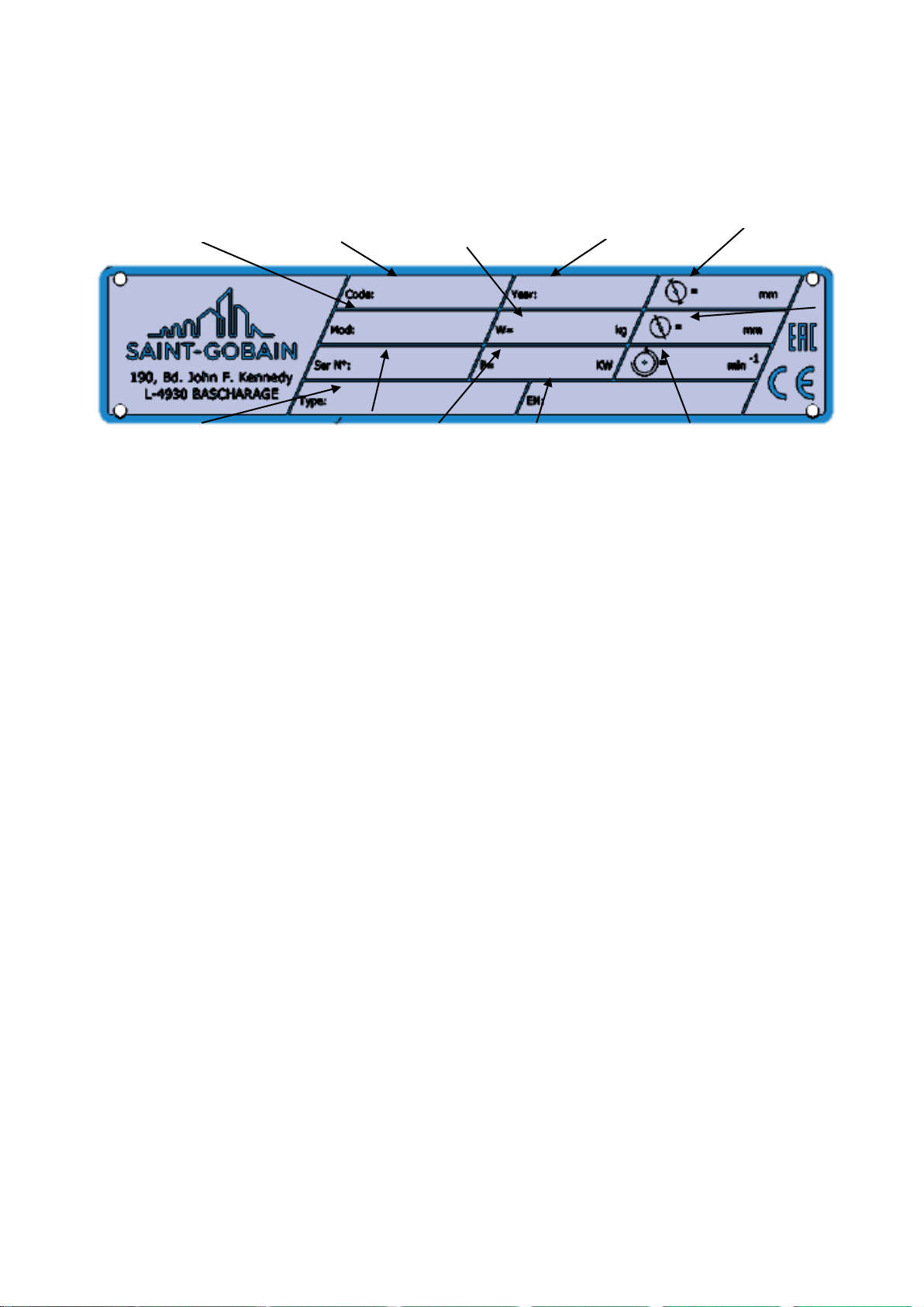
1.2 Machine plate
Important data can be found on the following plate located on the machine:
1.3 Safety instructions for particular operating phases
Before commencing work
Read the present operator’s instructions booklet carefully.
Before commencing work, make yourself familiar with the working environment at the place of
use. The working environment includes: obstacles in the area of work and manoeuvre, the
firmness of the floor, necessary protection at the site relating to public thoroughfares and the
availability of help in the event of accidents.
Check for correct mounting of the tool regularly.
Immediately remove damaged or badly worn tools, as they endanger the operator whilst
rotating.
Always use the machine with the safety guard ring and protection guards in position.
Only fit NORTON blades or plates to the machine! The use of other tools can damage the
machine!
Attention is drawn to the use of BS2092 safety goggles in conformity with specified Processes
No.8 of the Protection of Eyes Regulation 1974, Regulation 2(2) Part 1.
Petrol powered machines:
Always use the fuel advised.
In confined areas, exhaust gases should be evacuated and the job site properly aerated.
Petrol machines, which by their nature emit toxic exhaust gases, must not be used in places
prohibited by the Health at Work etc. Act 1974 or which are prohibited by Factory Inspectors or
Safety Officers.
Fuel is flammable. Before filling the tank, shut down the engine, extinguish all open flames and
do not smoke. Take care that no petrol is spilled on any engine part. Always wipe up spilled fuel.