NOSHOK 800 Series User manual

CORPORATE HEADQUARTERS
1010 West Bagley Rd. • Berea, OH 44017
440.243.0888 • FAX 440.243.3472
E-mail: [email protected]
Web: www.noshok.com
Wiring Diagrams & Electrical
Connections for:
100, 200, 300, 612, 613, 615/616,
640, 660, and 800 Series
NOSHOK
TRANSMITTERS
TRANSDUCERS
Installation:
NOSHOK pressure transmitters/transducers may
be mounted in any plane with negligible effect on
performance. Although these units are designed
and manufactured to withstand substantial shock
and vibration, it is recommended that they be
mounted in an area of minimal vibration. Always
use a wrench on the wrench flats when installing.
NEVER use a pipe wrench on the housing or in the
area of the electrical connection.
Maintenance/Calibration:
NOSHOK pressure transmitters/transducers
require no maintenance. Recalibration is
dependent on the users Quality Assurance
Program. If no program is in place, NOSHOK
recommends a 1 year cycle.
Alignment Procedure (applies only to 100,
200, 615/616, and 640 series):
Using a pressure source and meter with adequate
accuracy, perform the following steps:
• Open sensor
• With no pressure applied,
adjust the “Z”
potentiometer for the
correct Zero output
• Apply the correct full scale
pressure to the unit
• Adjust the “S”
potentiometer for the
correct Span output
NWD 08-3
Span
Zero
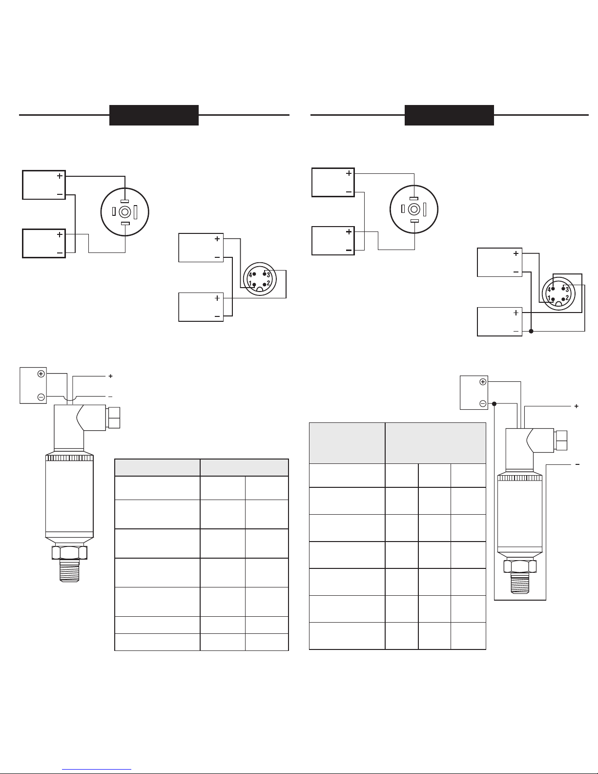
SERIES 660 SERIES 800
4 mA to 20 mA, 2 wire
Power
Supply
+ Supply
Output + Output
Load Limitations
4 mA to 20 mA Output Only
Vmin = 10V + (.020 x RL)
RL = RS + RW
RL = Loop Resistance (ohms)
RS = Sense Resistance (ohms)
RW = Wire Resistance (ohms)
Series 800 4 mA to 20 mA
CONNECTION TYPE (CODE) + SUPPLY + OUTPUT
Hirschmann (8 or 14) 1 2
Hirschmann w/ Cable (1) Red Black
M12 x 1, 4-Pin (25) 1 3
Series 800 0-10 Vdc
CONNECTION TYPE (CODE) + SUPPLY COMMON + OUTPUT
Hirschmann (8 or 14) 1 2 3
Hirschmann w/ Cable (1) Red Black White
M12 x 1, 4-Pin (25) 1 3 4
Example: Red / 1 = Applicable color wire / din plug number.
Load Limitations
4 mA to 20 mA Output Only
Vmin = 10V + (.020 x RL)
RL = RS + RW
RL = Loop Resistance (ohms)
RS = Sense Resistance (ohms)
RW = Wire Resistance (ohms)
Series 660 4 mA to 20 mA
CONNECTION TYPE (CODE) + SUPPLY + OUTPUT
Mini-Hirschmann (7) 1 2
Mini-Hirschmann w/ Cable (1) Red Black
M12 x 1, 4-Pin (25) 1 3
Integral Cable (36) Brown Green
Wiring - M12 x 1 4-pin
round connector
Wiring - Mini-Hirschmann
connector
Series 660 1-5 Vdc, 0.1-10 Vdc
CONNECTION TYPE (CODE) + SUPPLY COMMON + OUTPUT
Mini-Hirschmann (7) 1 2 3
Mini-Hirschmann w/ Cable (1) Red Black White
M12 x 1, 4-Pin (25) 1 3 4
Integral Cable (36) Brown Green White
Current output, 2 wire
Power
Supply
+ Supply
Output + Output
1
32
Power
Supply
+ Supply
Output + Output
Common
1
32
Voltage output, 3 wire
Current output, 2 wire
Power
Supply
+ Supply
Output + Output
Voltage output, 3 wire
Power
Supply
+ Supply
Output
+ Output
Common
0 Vdc to 10 Vdc, 3 wire
Power
Supply
+ Supply
Output + Output
Common
Red
Black White
Power
Supply
Output
Load Limitations
4 mA to 20 mA Output Only
Vmin = 10V + (.020 x RL)
RL = RS + RW
RL = Loop Resistance (ohms)
RS = Sense Resistance (ohms)
RW = Wire Resistance (ohms)
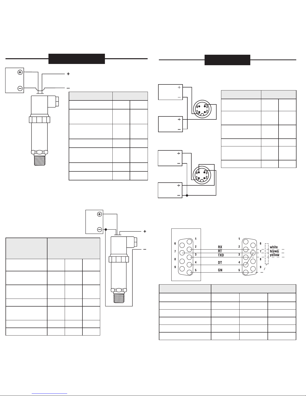
Series 100 4 mA to 20 mA
CONNECTION TYPE
(CODE) + SUPPLY + OUTPUT
Mini-Hirschmann
(7) 1 2
Mini-Hirschmann
w/ Cable (1) Red Black
4 or 6 Pin Bendix
(2 or 3) A B
1/2" NPT Conduit
w/ Cable (6) Red Black
M12 x 1, 4-Pin (25) 1 3
Integral Cable (36) Red Black
Series 200
0-5 Vdc, 1-5 Vdc,
1-6 Vdc,
0-10 Vdc, 1-11 Vdc
CONNECTION TYPE
(CODE) + SUPPLY COMMON + OUTPUT
Mini-Hirschmann
(7) 1 2 3
Mini-Hirschmann
w/ Cable (1) Red Black White
4 or 6 Pin Bendix
(2 or 3) A B C
1/2" NPT Conduit
w/ Cable (6) Red Black White
M12 x 1,
4-Pin (25) 1 3 4
Integral Cable
(36) Red Black White
SERIES 300 SERIES 612 & 613 SERIES 640
SERIES 615/616
Wiring -
M12 x 1 4-pin
round connector
Power
Supply
+ Supply
Output + Output
Wiring -
Mini-Hirschmann
connector
Current output, 2 wire
Power
Supply
+ Supply
Output + Output
1
32
Power
Supply Output
Red Black
2 WIRE
WIRING
DIAGRAM
EXAMPLE
SERIES 100 SERIES 200
Wiring -
Mini-Hirschmann
connector
Voltage output, 3 wire
Power
Supply
+ Supply
Output + Output
1
32
Common
Wiring -
M12 x 1 4-pin
round connector
Power
Supply
+ Supply
Output + Output
Common Load Limitations
4 mA to 20 mA Output Only
Vmin = [10V + (.020 x RL)] - O.04354 x
cable length
RL = RS + RW
RL = Loop Resistance (ohms)
RS = Sense Resistance (ohms)
RW = Wire Resistance (ohms)
Ft.
Series 612/613 4 mA to 20 mA
CONNECTION TYPE + SUPPLY + OUTPUT CASE GROUND
Cable Red Black Blue
Series 612/613 0-5 Vdc, 0-10 Vdc,
0.5 to 2.5 Vdc
CONNECTION
TYPE + SUPPLY COMMON + OUTPUT CASE
GROUND
Cable Red Black White Blue
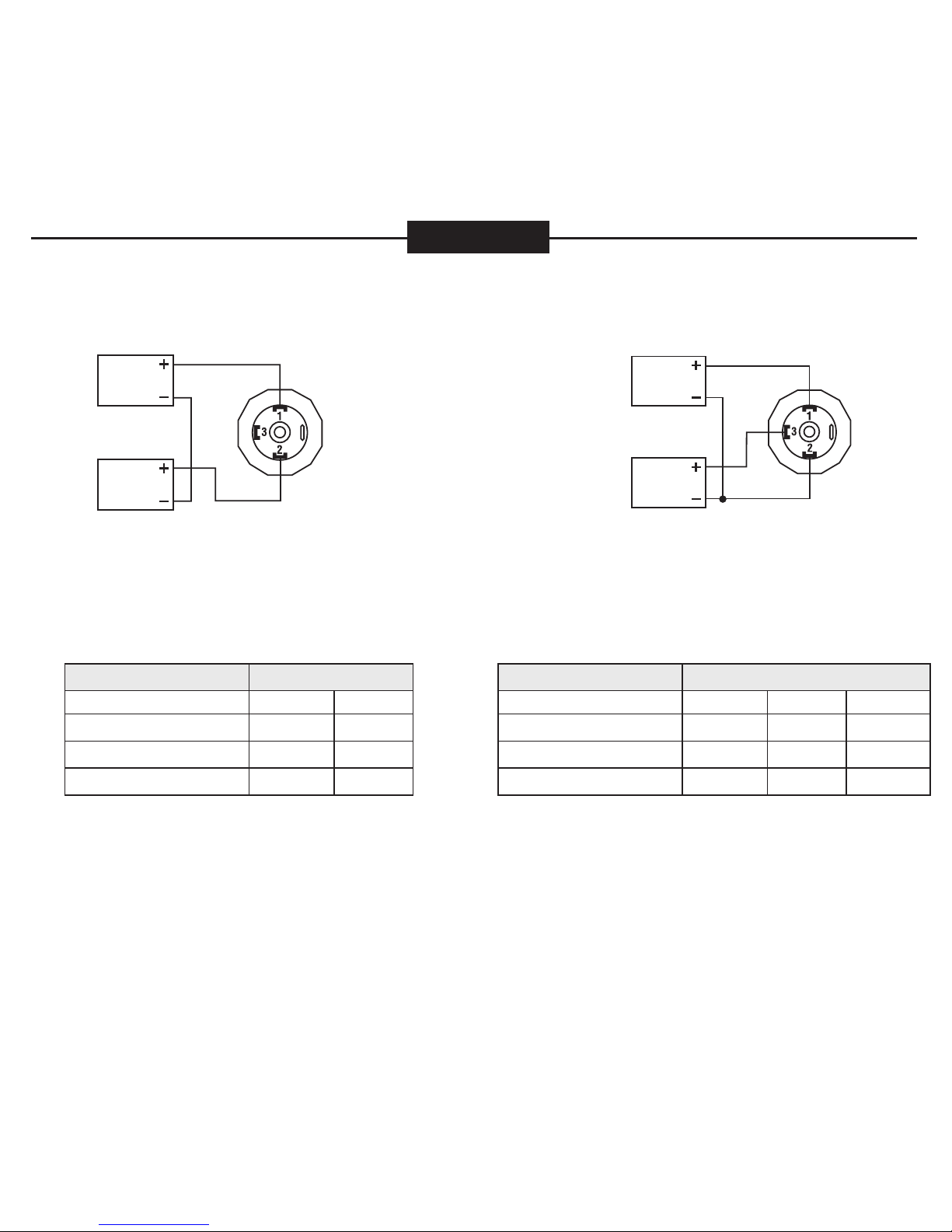
Series 300 4 mA to 20 mA
CONNECTION TYPE (CODE) + SUPPLY + OUTPUT
Hirschmann
(7, 8 or 14) 1 2
Hirschmann
w/ Cable (1) Red Black
M12 x 1, 4-Pin (25) 1 3
Integral Cable (36) Brown Blue
Power
Supply Output
Red
Black
2 WIRE WIRING
DIAGRAM EXAMPLE
Load Limitations 4 mA to 20 mA Output Only
Vmin = 10V + (.020 x RL)
RL = RS + RW
RL = Loop Resistance (ohms)
RS = Sense Resistance (ohms)
RW = Wire Resistance (ohms)
Series 300 0-5 Vdc, 1-5 Vdc, 1-6 Vdc,
0-10 Vdc, 1-11 Vdc
CONNECTION TYPE
(CODE) + SUPPLY COMMON + OUTPUT
Hirschmann
(7, 8 or 14) 1 2 3
Hirschmann
w/ Cable (1) Red Black White
M12 x 1,
4-Pin (25) 1 3 4
Integral Cable
(36) Brown Blue Black
Power
Supply
Output
Red
Black White
2 WIRE WIRING
DIAGRAM EXAMPLE
Power
Supply Output
Red Black
Blue
3 WIRE WIRING
DIAGRAM EXAMPLE
Load Limitations
4 mA to 20 mA
Output Only
Vmin = 10V + (.020 x RL)
RL = RS + RW
RL = Loop Resistance (ohms)
RS = Sense Resistance (ohms)
RW = Wire Resistance (ohms)
Series 615/616 4 mA to 20 mA
CONNECTION TYPE (CODE) + SUPPLY + OUTPUT
Hirschmann
(8 or 14) 1 2
Hirschmann
w/ Cable (1) Red Black
6 Pin Bendix (3) A B
1/2" NPT Conduit
w/ Cable (6) Red Black
M12 x 1, 4-Pin (25) 1 3
Integral Cable (36) Red Black
Series 615/616
0-5 Vdc, 1-5 Vdc,
1-6 Vdc,
0-10 Vdc, 1-11 Vdc
CONNECTION TYPE
(CODE) + SUPPLY COMMON + OUTPUT
Hirschmann
(8 or 14) 1 2 3
Hirschmann
w/ Cable (1) Red Black White
6 Pin Bendix (3) A B C
1/2" NPT Conduit
w/ Cable (6) Red Black White
M12 x 1, 4-Pin (25) 1 3 4
Integral Cable (36) Red Black White
Power
Supply Output
Red Black
2 WIRE WIRING
DIAGRAM EXAMPLE
3 WIRE WIRING
DIAGRAM EXAMPLE
3 WIRE WIRING
DIAGRAM EXAMPLE
Power
Supply
Output
Red
Black
Blue
White
Power
Supply
Output
Red
Black White
3 WIRE WIRING
DIAGRAM EXAMPLE
Wiring - M12 x 1 4-pin
round connector
Current output, 2 wire
Power
Supply
+ Supply
Output + Output
Voltage output, 3 wire
Common
Power
Supply
+ Supply
Output
+ Output
Load Limitations
4 mA to 20 mA Output Only
Vmin = 10V + (.020 x RL)
RL = RS + RW
RL = Loop Resistance (ohms)
RS = Sense Resistance (ohms)
RW = Wire Resistance (ohms)
RS 232 Interface
Pressure Sensor
Series 640 0-5 Vdc, 0-10 Vdc, 0-20 mA
CONNECTION TYPE (CODE) + SUPPLY COMMON + OUTPUT
Hirschmann (8 or 14) 1 2 3
Hirschmann w/ Cable (1) Red Black White
6 Pin Bendix (3) A B C
M12 x 1, 4-Pin (25) 1 3 4
Integral Cable (36) Brown Black Blue
Series 640 4 mA to 20 mA
CONNECTION
TYPE (CODE) + SUPPLY + OUTPUT
Hirschmann
(8 or 14) 1 2
Hirschmann
w/ Cable (1) Red Black
6 Pin Bendix (3) A B
M12 x 1,
4-Pin (25) 1 3
Integral Cable (36) Brown Blue

Red
Black White
Power
Supply
Output
Load Limitations
4 mA to 20 mA Output Only
Vmin = 10V + (.020 x RL)
RL = RS + RW
RL = Loop Resistance (ohms)
RS = Sense Resistance (ohms)
RW = Wire Resistance (ohms)
Series 100 4 mA to 20 mA
CONNECTION TYPE
(CODE) + SUPPLY + OUTPUT
Mini-Hirschmann
(7) 1 2
Mini-Hirschmann
w/ Cable (1) Red Black
4 or 6 Pin Bendix
(2 or 3) A B
1/2" NPT Conduit
w/ Cable (6) Red Black
M12 x 1, 4-Pin (25) 1 3
Integral Cable (36) Red Black
Series 200
0-5 Vdc, 1-5 Vdc,
1-6 Vdc,
0-10 Vdc, 1-11 Vdc
CONNECTION TYPE
(CODE) + SUPPLY COMMON + OUTPUT
Mini-Hirschmann
(7) 1 2 3
Mini-Hirschmann
w/ Cable (1) Red Black White
4 or 6 Pin Bendix
(2 or 3) A B C
1/2" NPT Conduit
w/ Cable (6) Red Black White
M12 x 1,
4-Pin (25) 1 3 4
Integral Cable
(36) Red Black White
SERIES 300 SERIES 612 & 613 SERIES 640
SERIES 615/616
Wiring -
M12 x 1 4-pin
round connector
Power
Supply
+ Supply
Output + Output
Wiring -
Mini-Hirschmann
connector
Current output, 2 wire
Power
Supply
+ Supply
Output + Output
1
32
Power
Supply Output
Red Black
2 WIRE
WIRING
DIAGRAM
EXAMPLE
SERIES 100 SERIES 200
Wiring -
Mini-Hirschmann
connector
Voltage output, 3 wire
Power
Supply
+ Supply
Output + Output
1
32
Common
Wiring -
M12 x 1 4-pin
round connector
Power
Supply
+ Supply
Output + Output
Common Load Limitations
4 mA to 20 mA Output Only
Vmin = [10V + (.020 x RL)] - O.04354 x
cable length
RL = RS + RW
RL = Loop Resistance (ohms)
RS = Sense Resistance (ohms)
RW = Wire Resistance (ohms)
Ft.
Series 612/613 4 mA to 20 mA
CONNECTION TYPE + SUPPLY + OUTPUT CASE GROUND
Cable Red Black Blue
Series 612/613 0-5 Vdc, 0-10 Vdc,
0.5 to 2.5 Vdc
CONNECTION
TYPE + SUPPLY COMMON + OUTPUT CASE
GROUND
Cable Red Black White Blue
Series 300 4 mA to 20 mA
CONNECTION TYPE (CODE) + SUPPLY + OUTPUT
Hirschmann
(7, 8 or 14) 1 2
Hirschmann
w/ Cable (1) Red Black
M12 x 1, 4-Pin (25) 1 3
Integral Cable (36) Brown Blue
Power
Supply Output
Red
Black
2 WIRE WIRING
DIAGRAM EXAMPLE
Load Limitations 4 mA to 20 mA Output Only
Vmin = 10V + (.020 x RL)
RL = RS + RW
RL = Loop Resistance (ohms)
RS = Sense Resistance (ohms)
RW = Wire Resistance (ohms)
Series 300 0-5 Vdc, 1-5 Vdc, 1-6 Vdc,
0-10 Vdc, 1-11 Vdc
CONNECTION TYPE
(CODE) + SUPPLY COMMON + OUTPUT
Hirschmann
(7, 8 or 14) 1 2 3
Hirschmann
w/ Cable (1) Red Black White
M12 x 1,
4-Pin (25) 1 3 4
Integral Cable
(36) Brown Blue Black
Power
Supply
Output
Red
Black White
2 WIRE WIRING
DIAGRAM EXAMPLE
Power
Supply Output
Red Black
Blue
3 WIRE WIRING
DIAGRAM EXAMPLE
Load Limitations
4 mA to 20 mA
Output Only
Vmin = 10V + (.020 x RL)
RL = RS + RW
RL = Loop Resistance (ohms)
RS = Sense Resistance (ohms)
RW = Wire Resistance (ohms)
Series 615/616 4 mA to 20 mA
CONNECTION TYPE (CODE) + SUPPLY + OUTPUT
Hirschmann
(8 or 14) 1 2
Hirschmann
w/ Cable (1) Red Black
6 Pin Bendix (3) A B
1/2" NPT Conduit
w/ Cable (6) Red Black
M12 x 1, 4-Pin (25) 1 3
Integral Cable (36) Red Black
Series 615/616
0-5 Vdc, 1-5 Vdc,
1-6 Vdc,
0-10 Vdc, 1-11 Vdc
CONNECTION TYPE
(CODE) + SUPPLY COMMON + OUTPUT
Hirschmann
(8 or 14) 1 2 3
Hirschmann
w/ Cable (1) Red Black White
6 Pin Bendix (3) A B C
1/2" NPT Conduit
w/ Cable (6) Red Black White
M12 x 1, 4-Pin (25) 1 3 4
Integral Cable (36) Red Black White
Power
Supply Output
Red Black
2 WIRE WIRING
DIAGRAM EXAMPLE
3 WIRE WIRING
DIAGRAM EXAMPLE
3 WIRE WIRING
DIAGRAM EXAMPLE
Power
Supply
Output
Red
Black
Blue
White
Power
Supply
Output
Red
Black White
3 WIRE WIRING
DIAGRAM EXAMPLE
Wiring - M12 x 1 4-pin
round connector
Current output, 2 wire
Power
Supply
+ Supply
Output + Output
Voltage output, 3 wire
Common
Power
Supply
+ Supply
Output
+ Output
Load Limitations
4 mA to 20 mA Output Only
Vmin = 10V + (.020 x RL)
RL = RS + RW
RL = Loop Resistance (ohms)
RS = Sense Resistance (ohms)
RW = Wire Resistance (ohms)
RS 232 Interface
Pressure Sensor
Series 640 0-5 Vdc, 0-10 Vdc, 0-20 mA
CONNECTION TYPE (CODE) + SUPPLY COMMON + OUTPUT
Hirschmann (8 or 14) 1 2 3
Hirschmann w/ Cable (1) Red Black White
6 Pin Bendix (3) A B C
M12 x 1, 4-Pin (25) 1 3 4
Integral Cable (36) Brown Black Blue
Series 640 4 mA to 20 mA
CONNECTION
TYPE (CODE) + SUPPLY + OUTPUT
Hirschmann
(8 or 14) 1 2
Hirschmann
w/ Cable (1) Red Black
6 Pin Bendix (3) A B
M12 x 1,
4-Pin (25) 1 3
Integral Cable (36) Brown Blue
Red
Black White
Power
Supply
Output
Load Limitations
4 mA to 20 mA Output Only
Vmin = 10V + (.020 x RL)
RL = RS + RW
RL = Loop Resistance (ohms)
RS = Sense Resistance (ohms)
RW = Wire Resistance (ohms)
Series 100 4 mA to 20 mA
CONNECTION TYPE
(CODE) + SUPPLY + OUTPUT
Mini-Hirschmann
(7) 1 2
Mini-Hirschmann
w/ Cable (1) Red Black
4 or 6 Pin Bendix
(2 or 3) A B
1/2" NPT Conduit
w/ Cable (6) Red Black
M12 x 1, 4-Pin (25) 1 3
Integral Cable (36) Red Black
Series 200
0-5 Vdc, 1-5 Vdc,
1-6 Vdc,
0-10 Vdc, 1-11 Vdc
CONNECTION TYPE
(CODE) + SUPPLY COMMON + OUTPUT
Mini-Hirschmann
(7) 1 2 3
Mini-Hirschmann
w/ Cable (1) Red Black White
4 or 6 Pin Bendix
(2 or 3) A B C
1/2" NPT Conduit
w/ Cable (6) Red Black White
M12 x 1,
4-Pin (25) 1 3 4
Integral Cable
(36) Red Black White
SERIES 300 SERIES 612 & 613 SERIES 640
SERIES 615/616
Wiring -
M12 x 1 4-pin
round connector
Power
Supply
+ Supply
Output + Output
Wiring -
Mini-Hirschmann
connector
Current output, 2 wire
Power
Supply
+ Supply
Output + Output
1
32
Power
Supply Output
Red Black
2 WIRE
WIRING
DIAGRAM
EXAMPLE
SERIES 100 SERIES 200
Wiring -
Mini-Hirschmann
connector
Voltage output, 3 wire
Power
Supply
+ Supply
Output + Output
1
32
Common
Wiring -
M12 x 1 4-pin
round connector
Power
Supply
+ Supply
Output + Output
Common Load Limitations
4 mA to 20 mA Output Only
Vmin = [10V + (.020 x RL)] - O.04354 x
cable length
RL = RS + RW
RL = Loop Resistance (ohms)
RS = Sense Resistance (ohms)
RW = Wire Resistance (ohms)
Ft.
Series 612/613 4 mA to 20 mA
CONNECTION TYPE + SUPPLY + OUTPUT CASE GROUND
Cable Red Black Blue
Series 612/613 0-5 Vdc, 0-10 Vdc,
0.5 to 2.5 Vdc
CONNECTION
TYPE + SUPPLY COMMON + OUTPUT CASE
GROUND
Cable Red Black White Blue
Series 300 4 mA to 20 mA
CONNECTION TYPE (CODE) + SUPPLY + OUTPUT
Hirschmann
(7, 8 or 14) 1 2
Hirschmann
w/ Cable (1) Red Black
M12 x 1, 4-Pin (25) 1 3
Integral Cable (36) Brown Blue
Power
Supply Output
Red
Black
2 WIRE WIRING
DIAGRAM EXAMPLE
Load Limitations 4 mA to 20 mA Output Only
Vmin = 10V + (.020 x RL)
RL = RS + RW
RL = Loop Resistance (ohms)
RS = Sense Resistance (ohms)
RW = Wire Resistance (ohms)
Series 300 0-5 Vdc, 1-5 Vdc, 1-6 Vdc,
0-10 Vdc, 1-11 Vdc
CONNECTION TYPE
(CODE) + SUPPLY COMMON + OUTPUT
Hirschmann
(7, 8 or 14) 1 2 3
Hirschmann
w/ Cable (1) Red Black White
M12 x 1,
4-Pin (25) 1 3 4
Integral Cable
(36) Brown Blue Black
Power
Supply
Output
Red
Black White
2 WIRE WIRING
DIAGRAM EXAMPLE
Power
Supply Output
Red Black
Blue
3 WIRE WIRING
DIAGRAM EXAMPLE
Load Limitations
4 mA to 20 mA
Output Only
Vmin = 10V + (.020 x RL)
RL = RS + RW
RL = Loop Resistance (ohms)
RS = Sense Resistance (ohms)
RW = Wire Resistance (ohms)
Series 615/616 4 mA to 20 mA
CONNECTION TYPE (CODE) + SUPPLY + OUTPUT
Hirschmann
(8 or 14) 1 2
Hirschmann
w/ Cable (1) Red Black
6 Pin Bendix (3) A B
1/2" NPT Conduit
w/ Cable (6) Red Black
M12 x 1, 4-Pin (25) 1 3
Integral Cable (36) Red Black
Series 615/616
0-5 Vdc, 1-5 Vdc,
1-6 Vdc,
0-10 Vdc, 1-11 Vdc
CONNECTION TYPE
(CODE) + SUPPLY COMMON + OUTPUT
Hirschmann
(8 or 14) 1 2 3
Hirschmann
w/ Cable (1) Red Black White
6 Pin Bendix (3) A B C
1/2" NPT Conduit
w/ Cable (6) Red Black White
M12 x 1, 4-Pin (25) 1 3 4
Integral Cable (36) Red Black White
Power
Supply Output
Red Black
2 WIRE WIRING
DIAGRAM EXAMPLE
3 WIRE WIRING
DIAGRAM EXAMPLE
3 WIRE WIRING
DIAGRAM EXAMPLE
Power
Supply
Output
Red
Black
Blue
White
Power
Supply
Output
Red
Black White
3 WIRE WIRING
DIAGRAM EXAMPLE
Wiring - M12 x 1 4-pin
round connector
Current output, 2 wire
Power
Supply
+ Supply
Output + Output
Voltage output, 3 wire
Common
Power
Supply
+ Supply
Output
+ Output
Load Limitations
4 mA to 20 mA Output Only
Vmin = 10V + (.020 x RL)
RL = RS + RW
RL = Loop Resistance (ohms)
RS = Sense Resistance (ohms)
RW = Wire Resistance (ohms)
RS 232 Interface
Pressure Sensor
Series 640 0-5 Vdc, 0-10 Vdc, 0-20 mA
CONNECTION TYPE (CODE) + SUPPLY COMMON + OUTPUT
Hirschmann (8 or 14) 1 2 3
Hirschmann w/ Cable (1) Red Black White
6 Pin Bendix (3) A B C
M12 x 1, 4-Pin (25) 1 3 4
Integral Cable (36) Brown Black Blue
Series 640 4 mA to 20 mA
CONNECTION
TYPE (CODE) + SUPPLY + OUTPUT
Hirschmann
(8 or 14) 1 2
Hirschmann
w/ Cable (1) Red Black
6 Pin Bendix (3) A B
M12 x 1,
4-Pin (25) 1 3
Integral Cable (36) Brown Blue

CORPORATE HEADQUARTERS
1010 West Bagley Rd. • Berea, OH 44017
440.243.0888 • FAX 440.243.3472
Web: www.noshok.com
Wiring Diagrams & Electrical
Connections for:
100, 200, 300, 612, 613, 615/616,
640, 660, and 800 Series
NOSHOK
TRANSMITTERS
TRANSDUCERS
Installation:
NOSHOK pressure transmitters/transducers may
be mounted in any plane with negligible effect on
performance. Although these units are designed
and manufactured to withstand substantial shock
and vibration, it is recommended that they be
mounted in an area of minimal vibration. Always
use a wrench on the wrench flats when installing.
NEVER use a pipe wrench on the housing or in the
area of the electrical connection.
Maintenance/Calibration:
NOSHOK pressure transmitters/transducers
require no maintenance. Recalibration is
dependent on the users Quality Assurance
Program. If no program is in place, NOSHOK
recommends a 1 year cycle.
Alignment Procedure (applies only to 100,
200, 615/616, and 640 series):
Using a pressure source and meter with adequate
accuracy, perform the following steps:
• Open sensor
• With no pressure applied,
adjust the “Z”
potentiometer for the
correct Zero output
• Apply the correct full scale
pressure to the unit
• Adjust the “S”
potentiometer for the
correct Span output
NWD 08-3
Span
Zero
SERIES 660 SERIES 800
4 mA to 20 mA, 2 wire
Power
Supply
+ Supply
Output + Output
Load Limitations
4 mA to 20 mA Output Only
Vmin = 10V + (.020 x RL)
RL = RS + RW
RL = Loop Resistance (ohms)
RS = Sense Resistance (ohms)
RW = Wire Resistance (ohms)
Series 800 4 mA to 20 mA
CONNECTION TYPE (CODE) + SUPPLY + OUTPUT
Hirschmann (8 or 14) 1 2
Hirschmann w/ Cable (1) Red Black
M12 x 1, 4-Pin (25) 1 3
Series 800 0-10 Vdc
CONNECTION TYPE (CODE) + SUPPLY COMMON + OUTPUT
Hirschmann (8 or 14) 1 2 3
Hirschmann w/ Cable (1) Red Black White
M12 x 1, 4-Pin (25) 1 3 4
Example: Red / 1 = Applicable color wire / din plug number.
Load Limitations
4 mA to 20 mA Output Only
Vmin = 10V + (.020 x RL)
RL = RS + RW
RL = Loop Resistance (ohms)
RS = Sense Resistance (ohms)
RW = Wire Resistance (ohms)
Series 660 4 mA to 20 mA
CONNECTION TYPE (CODE) + SUPPLY + OUTPUT
Mini-Hirschmann (7) 1 2
Mini-Hirschmann w/ Cable (1) Red Black
M12 x 1, 4-Pin (25) 1 3
Integral Cable (36) Brown Green
Wiring - M12 x 1 4-pin
round connector
Wiring - Mini-Hirschmann
connector
Series 660 1-5 Vdc, 0.1-10 Vdc
CONNECTION TYPE (CODE) + SUPPLY COMMON + OUTPUT
Mini-Hirschmann (7) 1 2 3
Mini-Hirschmann w/ Cable (1) Red Black White
M12 x 1, 4-Pin (25) 1 3 4
Integral Cable (36) Brown Green White
Current output, 2 wire
Power
Supply
+ Supply
Output + Output
1
32
Power
Supply
+ Supply
Output + Output
Common
1
32
Voltage output, 3 wire
Current output, 2 wire
Power
Supply
+ Supply
Output + Output
Voltage output, 3 wire
Power
Supply
+ Supply
Output
+ Output
Common
0 Vdc to 10 Vdc, 3 wire
Power
Supply
+ Supply
Output + Output
Common
CORPORATE HEADQUARTERS
1010 West Bagley Rd. • Berea, OH 44017
440.243.0888 • FAX 440.243.3472
Web: www.noshok.com
Wiring Diagrams & Electrical
Connections for:
100, 200, 300, 612, 613, 615/616,
640, 660, and 800 Series
NOSHOK
TRANSMITTERS
TRANSDUCERS
Installation:
NOSHOK pressure transmitters/transducers may
be mounted in any plane with negligible effect on
performance. Although these units are designed
and manufactured to withstand substantial shock
and vibration, it is recommended that they be
mounted in an area of minimal vibration. Always
use a wrench on the wrench flats when installing.
NEVER use a pipe wrench on the housing or in the
area of the electrical connection.
Maintenance/Calibration:
NOSHOK pressure transmitters/transducers
require no maintenance. Recalibration is
dependent on the users Quality Assurance
Program. If no program is in place, NOSHOK
recommends a 1 year cycle.
Alignment Procedure (applies only to 100,
200, 615/616, and 640 series):
Using a pressure source and meter with adequate
accuracy, perform the following steps:
• Open sensor
• With no pressure applied,
adjust the “Z”
potentiometer for the
correct Zero output
• Apply the correct full scale
pressure to the unit
• Adjust the “S”
potentiometer for the
correct Span output
NWD 08-3
Span
Zero
SERIES 660
SERIES 800
4 mA to 20 mA, 2 wire
Power
Supply
+ Supply
Output + Output
Load Limitations
4 mA to 20 mA Output Only
Vmin = 10V + (.020 x RL)
RL = RS + RW
RL = Loop Resistance (ohms)
RS = Sense Resistance (ohms)
RW = Wire Resistance (ohms)
Series 800 4 mA to 20 mA
CONNECTION TYPE (CODE) + SUPPLY + OUTPUT
Hirschmann (8 or 14) 1 2
Hirschmann w/ Cable (1) Red Black
M12 x 1, 4-Pin (25) 1 3
Series 800 0-10 Vdc
CONNECTION TYPE (CODE) + SUPPLY COMMON + OUTPUT
Hirschmann (8 or 14) 1 2 3
Hirschmann w/ Cable (1) Red Black White
M12 x 1, 4-Pin (25) 1 3 4
Example: Red / 1 = Applicable color wire / din plug number.
Load Limitations
4 mA to 20 mA Output Only
Vmin = 10V + (.020 x RL)
RL = RS + RW
RL = Loop Resistance (ohms)
RS = Sense Resistance (ohms)
RW = Wire Resistance (ohms)
Series 660 4 mA to 20 mA
CONNECTION TYPE (CODE) + SUPPLY + OUTPUT
Mini-Hirschmann (7) 1 2
Mini-Hirschmann w/ Cable (1) Red Black
M12 x 1, 4-Pin (25) 1 3
Integral Cable (36) Brown Green
Wiring - M12 x 1 4-pin
round connector
Wiring - Mini-Hirschmann
connector
Series 660 1-5 Vdc, 0.1-10 Vdc
CONNECTION TYPE (CODE) + SUPPLY COMMON + OUTPUT
Mini-Hirschmann (7) 1 2 3
Mini-Hirschmann w/ Cable (1) Red Black White
M12 x 1, 4-Pin (25) 1 3 4
Integral Cable (36) Brown Green White
Current output, 2 wire
Power
Supply
+ Supply
Output + Output
1
32
Power
Supply
+ Supply
Output + Output
Common
1
32
Voltage output, 3 wire
Current output, 2 wire
Power
Supply
+ Supply
Output + Output
Voltage output, 3 wire
Power
Supply
+ Supply
Output
+ Output
Common
0 Vdc to 10 Vdc, 3 wire
Power
Supply
+ Supply
Output + Output
Common
Other manuals for 800 Series
1
This manual suits for next models
9
Table of contents
Other NOSHOK Transmitter manuals

NOSHOK
NOSHOK King-Gage 5800 Series Service manual

NOSHOK
NOSHOK PT40 Series User manual

NOSHOK
NOSHOK 810 series User manual

NOSHOK
NOSHOK KING-GAGE ES2 5501 User manual

NOSHOK
NOSHOK 623 Series User manual

NOSHOK
NOSHOK KING-GAGE 5900 Use and care manual

NOSHOK
NOSHOK PT41 Series User manual

NOSHOK
NOSHOK 850 Series User manual

NOSHOK
NOSHOK 204 Series User manual

NOSHOK
NOSHOK 621 Series User manual


