NOSHOK King-Gage 5800 Series Service manual

EX-1861
"Intelligent" Pressure & Level Transmitter
ES3 Installation and Operation
Instructions Manual
58 Series
WARNING
Read the recommendations and warnings in this manual before the instrument is
installed. For personal safety, optimal use and maintenance of the KING-GAGE 5800
Series ES3 Transmitter, these instructions should be studied carefully.
KING-GAGE, A NOSHOK Company I 1010 West Bagley Road, Berea, Ohio 44017 I Ph: 855-367-2494 I www.king-gage.com

Page 2
ES3 "Intelligent" Pressure and Level Transmitter EX-1861
KING-GAGE, A NOSHOK Company
The information contained in this manual was accurate at
the time of release. Specifications are subject to change
without notice.
Warranty - All King Engineering products are guaranteed
to be free from defects in material and workmanship for
one year from the date of purchase. Any product or part
found to be defective under normal use within one year
of purchase will be repaired or replaced at no charge if
returned to the company at Berea. Ohio within ten days
of discovery of the defect. No other warranties, whether
expressed, implied, or statutory, including the warranties
of fitness for a particular purpose or merchantability, are
given by this agreement.
The exclusive remedy for nonconformity of these goods
shall be repair and/or replacement of the nonconforming
goods or parts.
Seller will not be liable for consequential damages resulting
from breach of this agreement. The term “consequential
damages” shall include but shall not be limited to damage
to all machines, equipment and goods other than the goods
sold hereby, interruption of production, loss of profits,
delays of any kind, administrative expense and overhead.
Revisions:
(A) March, 2008 – Original Release (applicable to ESR-
serial no. versions)
(B) August, 2008 – Illustrations based on encapsulated
board (ESR-serial no. versions)
(C) May, 2009 – molded cable w/ M12 plug connector
(D) August, 2009 – revised span adjustment ranges
(E) November, 2009 – ES2 Slimline version added
(F) August, 2011 – revised remote junction notes
(G) October, 2016 - model no.s (-3V) added for versions
with FKM seal

Page 3
ES3 "Intelligent" Pressure and Level Transmitter EX-1861
TABLE OF CONTENTS
SECTION
PAGE
1 Introduction...............................................................................................3
2 Dimensional Drawings .............................................................................3
3 Installing The Transmitter ........................................................................4
3.1 Mounting position .......................................................................................4
3.2 Mounting position effect .............................................................................4
3.3 Calibration...................................................................................................4
3.4 Connection Terminal....................................................................................4
3.5 Wiring .........................................................................................................4
4 Remaining .................................................................................................5
4.1 CE / EMC - Rules..........................................................................................5
4.2 Display and push buttons.............................................................................5
4.3 Display read out .........................................................................................5
5 Summary Programming Points ................................................................6
5.1 Explanation Programming Points..................................................................6
P101 Zero Adjustment (Zero) .......................................................................6
P102 Span Adjustment (Span)......................................................................6
P103 Cancel Mounting Position Effect .........................................................7
P104 Display Setting Of Units ......................................................................7
P105 Output Selection 4-20 Ma Or 20-4 Ma...............................................8
P106 Damping Adjustment..........................................................................8
P107 Temperature Units...............................................................................8
P108 Device Setup.......................................................................................8
P109 Readout..............................................................................................9
P110 Burst Mode (Hart®) ............................................................................9
P111 Information.......................................................................................10

Page 4
ES3 "Intelligent" Pressure and Level Transmitter EX-1861
1. INTRODUCTION
KING-GAGE 5800 Series ES3 Transmitters are solid-state pressure and level transmitters using a
piezoresistive silicon sensor with a very high burst pressure. The sensor element is mounted in a
Stainless Steel foot. Inside the foot a temperature sensor is also mounted to provide active temper-
ature compensation at the point of measurement, to minimize temperature and position error. A
compact, robust Stainless Steel flush diaphragm minimizes the amount of fill fluid and reduces the
potential for damage. Diaphragms are laser welded and helium leak tested. A very small amount
of oil fills the chamber surrounding the sensor and transfers pressure from the flush mounted dia-
phragm to the sensor.
Pressure on the sensor element creates a very small deflection of the silicon substrate and bridge
network. The resulting strain in the silicon resistors causes a change in the bridge resistance that
is proportional to the pressure applied. The transmitter electronics detects this change in bridge
resistance and converts it into a measuring value. The amplifier system is based on a single Inte-
grated Circuit, which ensures a perfect linearity in the output, all within an accuracy of 0.2 %. The
flush diaphragm technology ensures reliable long-term stability.
2. DIMENSIONAL DRAWINGS
5800 Series ES3 Transmitters Transmitter

Page 5
ES3 "Intelligent" Pressure and Level Transmitter EX-1861
3. INSTALLING THE TRANSMITTER
The transmitter’s diaphragm is protected with a special protection cap. Protect the diaphragm until
installation takes place. Do not damage the diaphragm.
3.1 MOUNTING POSITION
When the transmitter is mounted horizontally, the cable gland must be pointed downwards.
3.2 MOUNTING POSITION EFFECT
All transmitters are calibrated in vertical position (diaphragm points downwards). If the transmit-
ter is mounted in another position, there can be a little zero shift. (example 4.02 mA instead of
4.00 mA). After installation of the transmitter the zero must be set to 4.00 mA with P103 (cancel
mounting position effect). This will not affect the span.
3.3 CALIBRATION
All transmitters are fully calibrated at the factory, to customer specified range. If the calibration is
not specified, the transmitter will be calibrated at the maximum span.
3.4 CONNECTION TERMINAL
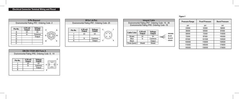
The figure above shows the wiring connection of the transmitter. The 2-wires must be connected
to the terminal board. The wiring terminals can be operated without a screwdriver. The opening
levers of the terminal can be lifted and pressed down by hand. Lift the opening levers of the termi-
nals and insert the corresponding wires. Press down the levers by hand. The terminal spring will
close and the wire is clamped.
3.5 WIRING
The transmitter must always be connected to ground. The transmitter must be connected with
standard two-wire shielded cable. Do not run signal wiring in open trays with power wiring, or
near heavy electrical equipment (Frequency controller or heavy pumps). Shielding must always be
connected at the side of the power supply. In case the process connection is already connected to
ground (by tank or pipe line) do not connect the instrument to ground. Please ensure that the in-
strument is not connected to ground twice to prevent an earth loop. In applications with synthetic
process connections, the enclosure (internal or external) must be connected to ground.
Reversing the polarity will not damage the transmitter, but the transmitter will not function until
the + and are properly connected.
Please ensure that the transmitter is not connected to ground twice to prevent an
earth loop.

Page 6
ES3 "Intelligent" Pressure and Level Transmitter EX-1861
4 REMAINING
4.1 / / EMC-RULES
These KING-GAGE transmitters are manufactured in accordance with the RFI/EMC directives and
comply with the CE standard. All transmitters are fitted with RFI filters, which provide optimum,
trouble-free operation. Our products are in conformity with EMC-Directive 2014/30/EU based on
test results using harmonized standards.
4.2 DISPLAY AND PUSH BUTTONS
The KING-GAGE 5800 Series ES3 Transmitter has a high contrast display for optimal readout. The
menu is controlled by 3 push buttons. Navigate with the up and down buttons through menus
and measuring values.
Enter a menu and confirm selections with the menu button.
Push the up button to browse through various menus and adjusting values.
Push the down button to browse through various menus and adjusting values.
Push the menu button to enter menus or confirm a selection.
Display – 5800 Series
4.3 DISPLAY READOUT
When the transmitter is powered, a startup screen with the software version and the pressure
range appears for a few seconds. After the startup screen the transmitter will automatically con-
tinue to the main screen with the actual measurement reading.

Page 7
ES3 "Intelligent" Pressure and Level Transmitter EX-1861
5 PUSH BUTTON FUNCTIONS
PROGRAM
POINT
NAME FUNCTION
P100 Menu-Exit menu Start and exit
P101 ZERO value Zero adjustment (ZERO 4 mA) with or without test pressure
P102 SPAN value Span adjustment (SPAN 20 mA) with or without test pressure
P103 MOUNT correction Cancel mounting position effect
P104 UNITS Selection of engineering units
P105 REVERSE mA Output selection: 4-20 mA or 20-4 mA
P106 DAMPING Adjustable damping: 0.00 till 25.00 seconds
P107 TEMP UNITS Temperature unit selection: Celsius or Fahrenheit
P108 DEVICE SETUP Configuration: Protection, HART, Display mode, Display update
P109 READOUT Readout options on display: Current, Unit, percentage and temperature
P110 BURST MODE Continuously broadcast a standard HART reply message
5.1. EXPLANATION PROGRAMMING POINTS
ZERO ADJUSTMENT (ZERO)
The transmitter is set to 0 psi at atmospheric pressure. The ZERO can be adjusted at
a lower or higher point. This will be explained step by step by an example.
Example: Increase ZERO till 1.45 psi.
1. The measuring unit of the transmitter is set to psi. If not, this can be selected by choosing the
right measuring unit in program point P104.
2. Navigate to program point P101, and push the menu button to enter the menu.
3. The actual measured value appears on the display.
4. Increase this value with the arrow button to 1.45 psi, push the button till save appear
on the display.
5. The transmitter will return to the home screen. The measurement value at atmospheric pressure
is now 1.45 psi. With a applied pressure of 1.45 psi, the transmitter will display 4 mA.
The transmitter can be adjusted to zero in a real process situation. The transmitter will measure
the pressure in an actual process. This measurement will be used as the zero value (4 mA).
1. Go to the home screen, the transmitter will display the actual measured value.
2. Push the button until the actual measured zero and the message ZERO PUSHED appear
on the display.
3. The transmitter will return to home screen.
SPAN ADJUSTMENT (SPAN)
This setting can be used to adjust the range (SPAN) according to an entered value or
adjusted with or without an applied pressure. The maximum pressure which can be
measured: The measurement at ZERO (P101) + the entered value SPAN (P102). If
the ZERO (P101) is increased, the maximum measured value will automatically set
higher at the same rate as the zero. This will be explained by an example.
Example: Measurement range 0 – 29 psi.
1. The span must be set at 29 psi
2. Navigate to program point P102, and push the menu button to enter the menu.

Page 8
ES3 "Intelligent" Pressure and Level Transmitter EX-1861
3. Adjust the SPAN with the push buttons to 29 psi and push the button until save appears
on the display.
4. The transmitter will return to the home screen.
The span can also be adjusted to a real process situation. The transmitter will measure the
pressure in an actual process. This measurement will be used as the span value (20 mA).
1. Go to the home screen, the transmitter will display the actual measured value.
2. Push the button until the actual measured span and the message SPAN PUSHED appear
on the display.
3. The transmitter will return to home screen.
P102 is the adjustment of the total span.
When a compound range must be adjusted (for example -14.5 till +43.5 psi), a
pan of 29 psi must be programmed.
The Zero (P101) must be set at -14.5 psi. The transmitter is adjusted at - 14.5 psi =
Zero and +43.5 psi = Span.
CANCEL MOUNTING POSITION EFFECT
All transmitters are calibrated vertically. If the transmitter is installed horizontally, the
transmitter has a small "mounting position" effect on the zero. The pressure value
displayed, will be for example 0.003 psi instead of 0.000 psi.
1. Navigate to program point P103, and push the menu button to enter the menu.
2. Two choices appear on the screen: Set and Reset.
Choosing Set will adjust the zero to 0.000 psi in the mounting position when applicable.
• Select Set, and push the menu button to confirm.
• The corrected is value is shown on the display.
• Push the menu button to save.
Choosing Reset will put the transmitter back to factory setting. (vertical adjustment)
•
Select Reset, and push the menu button to confirm to reset back to factory setting.
• The transmitter will return to the home screen.
Do not apply pressure when executing "Cancel mounting position effect"
DISPLAY SETTING OF UNITS
Various engineering units can be displayed on the display.
Factory setting = psi
1. Navigate to program point P104, and push the menu button to enter the menu.
2. Several engineering units can be selected. Each selected engineering unit is automatically
converted to the correct value of the corresponding unit.
3. Navigate through this menu and choose the required unit, push the menu button confirm.
4. The transmitter will return to the home screen. The measured reading will be displayed in the
selected unit in the home screen.
The selected pressure unit is only visible on the display when UNITS is
chosen in program point P109.

Page 9
ES3 "Intelligent" Pressure and Level Transmitter EX-1861
OUTPUT SELECTION 4-20 mA or 20-4 mA
Factory setting = 4 - 20 mA
1. Navigate to program point P105, and push the menu button to enter the menu.
2. Two choices appear on the screen: 4-20 and 20-4
3. Make an output choice and push the menu button to confirm.
4. The transmitter will return to the home screen.
DAMPING ADJUSTMENT
The transmitter has an adjustable damping between 0.00 to 25.00 seconds.
Factory setting = 0.00 seconds
1. Navigate to program point P106, and push the menu button to enter the menu.
2. Two choices appear on the screen: Set and Reset
Choosing Set allows a value to be set between 0.00 and 25.00 seconds.
• Select Set, and push the menu button to confirm.
• Adjust the damping with the push buttons and push the menu button to confirm.
• The transmitter will return to the home screen.
Choosing Reset will put the transmitter back to factory setting (0.00 seconds)
•
Select Reset, and push the menu button to confirm to reset back to factory setting.
• The transmitter will return to the home screen.
TEMPERATURE UNITS
In this menu the preferred temperature unit can be selected.
Factory setting = Fahrenheit
1. Navigate to program point P107, and push the menu button to enter the menu.
2. Two choices appear on the screen: Fahrenheit and Celsius.
3. Make a choice and push the menu button to confirm.
4. The transmitter will return to the home screen.
DEVICE SETUP
In this menu, several operational settings can be made for the transmitter and the display.
1. Navigate to program point P108, and push the menu button to enter the menu.
2. Five choices appear on the screen:
LocProtect : The transmitter can be protected against local adjustments
ComProtect : The transmitter can be protected against adjustments with HART.
HART®: Option for HART®5 and HART®7 communication.
DispMode : Option for turning the display on or off.
Disp.Upd.: Adjust the refresh rate of the measuring value on the display between 0.0 to
5.0 seconds. For example when this value is set to 2.0 seconds, the measuring value on the
display will be refreshed every 2 seconds.
• Select Set, and push the menu button to confirm.
• Adjust the setting with the push buttons and confirm with the menu button.

Page 10
ES3 "Intelligent" Pressure and Level Transmitter EX-1861
• The transmitter will return to the home screen.
• Choosing Reset will put the transmitter back to factory setting (0.0 seconds).
READOUT
In this menu, the type of readout on the display can be adjusted.
Factory Setting = Unit
1. Navigate to program point P109, and push the menu button to enter the menu.
2. Four choices appear on the screen:
Current : Current value (4 - 20 mA)
Unit : Pressure unit (Selected in P104)
Percentage : 0 - 100%
Temperature : Actual process temperature (°F or °C) Indication , accuracy depending on
sensor position.
3. Navigate to the desired choice, confirm by pushing the menu button.
4. The transmitter will return to the home screen.
BURST MODE (HART®)
The transmitter (Only when HART®is present) can be configured for Burst mode.
This will enable continuously broadcasting standard HART® reply messages.
1. Navigate to program point P110, and push the menu button to enter the menu.
2. Five choices appear on the screen: Mode Cntrl, Cmd number, Message, Period and Trigger
3. Select Mode Cntrl, and push to confirm.
4. Two choices appear on the screen: On and Off
• Choose On to turn on burst mode.
• Choose Off to turn off burst mode.
5. Select Message to select the burst message 0,1,2 or 3 and push the menu button to confirm.
6. Select Cmd number, and push the menu button to confirm.
Five choices appear on the screen:
• Cmd 01 = PRIMARY VARIABLE
• Cmd 02 = CURRENT AND PERCENT OF RANGE
• Cmd 03 = DYNAMIC VARIABLES AND CURRENT
• Cmd 09 = DEVICE VARIABLES WITH STATUS
• Cmd 48 = ADDITIONAL TRANSMITTER STATUS
Choose the preferable burst mode, and push menu button to confirm.
7. Select Period, and push the menu button to confirm.
Two choices appear on the screen: Max Time and Min Time
• Select Max Time to set the maximum amount of time when the message will be
send. This value can be set from 0.5 to 3600 seconds.
• Select Min Time to set the minimum amount of time when the message will be
send. This value can be set from 0.5 to 3600 seconds.
Enter the preferred value, and push the menu button to confirm.
8. Select Trigger, and push the menu button to confirm.

Page 11
ES3 "Intelligent" Pressure and Level Transmitter EX-1861
9. Five choices appear on the screen:
Continuous = The Burst message is send continuously.
Windowed = The Burst message is triggered when the measured value
deviates more than the specified trigger value.
Rising = The Burst message is triggered when the measured value rises above
the triggered value.
Falling = The Burst message is triggered when the measured value falls below
the triggered value.
On-Change = The Burst message is triggered when any value in the measuring
changing.
Choose the desired burst mode, and set the preferred parameters.
INFORMATION
This menu summarizes information about the configuration of the transmitter.
Below the contents of the information screen.

Page 12
ES3 "Intelligent" Pressure and Level Transmitter EX-1861
This manual suits for next models
1
Table of contents
Other NOSHOK Transmitter manuals

NOSHOK
NOSHOK KING-GAGE 5900 Use and care manual
NOSHOK
NOSHOK KING-GAGE ES2 5501 User manual

NOSHOK
NOSHOK 204 Series User manual

NOSHOK
NOSHOK 621 Series User manual

NOSHOK
NOSHOK 623 Series User manual
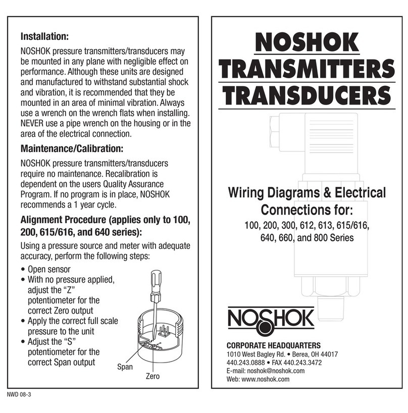
NOSHOK
NOSHOK 800 Series User manual
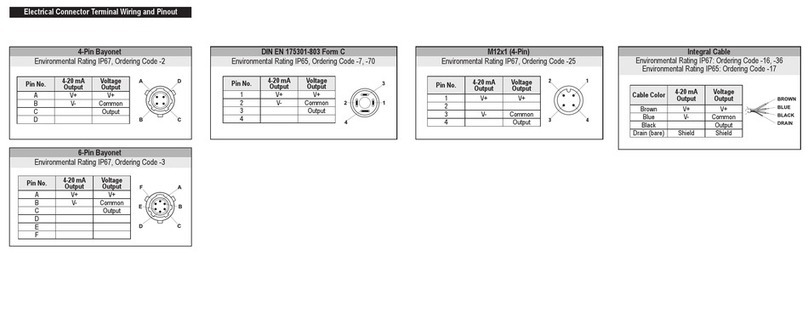
NOSHOK
NOSHOK PT40 Series User manual
NOSHOK
NOSHOK 850 Series User manual
NOSHOK
NOSHOK 810 series User manual
NOSHOK
NOSHOK PT41 Series User manual
