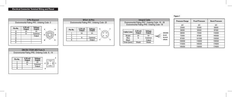
Mating connection cable assemblies are available as an accessory part
from NOSHOK. Refer to Electrical Connector Terminal Wiring and Pinout
for additional detail.
A pressure snubber may be installed to eliminate damaging hammer
effects. Water and conventional cleaning detergents are acceptable
cleaning agents. Cleaning with unsuitable cleaning agents may damage
the instrument or the product label. Do not use any aggressive chemical
agents or abrasive cloths or sponges.
Transmitter should be electrically common with earth via the process
connection.
• Refer to Power Supply Requirements and Ratings.
• Refer to Electrical Connector Terminal Wiring and Pinout.
• Refer to product technical specication for allowable minimum and
maximum temperature and pressure conditions.
General Operation
Pressure spikes in excess of the rated overpressure capability of the
transmitter may cause irreversible electrical and/or mechanical damage
to the pressure measuring and containing elements. Fluid hammer and
surges can destroy any pressure transmitter and must always be avoided.
Maintenance and Service
NOSHOK PT40 pressure transmitters are precisely calibrated, and
temperature compensated at the factory to ensure long and stable
performance.
The NOSHOK PT40 is capable of being eld adjusted for zero offset and
span by removing the top cap and adjusting the potentiometers. This
product is maintenance-free. Repairs should only be carried out by the
manufacturer.
Additional Notes
Any electrical device may be susceptible to damage when exposed to
static electrical charges. To avoid damage to the transmitter, observe the
following:
• The circuitry of the NOSHOK PT40 pressure transmitters is designed
to minimize the effect of electromagnetic and radio frequency interference.
To minimize susceptibility to noise, avoid running the termination
wiring in a conduit which contains high current AC power cables.
• Where possible avoid running the termination wiring near inductive
equipment.
NOTE: The shield and drain wire in the cable (if supplied) is not
connected to the transmitter body and is not a suitable ground.
4 mA to 20 mA output only
Vmin = 10V + (.020 x RL)
RL = RS + RW
RL = Loop resistance (ohms)
RS = Sense resistance (ohms)
RW = Wire resistance (ohms)
Load Limitations
4 mA to 20 mA Output
3-Wire Voltage Output
V+ = Supply voltage
V- = 4 mA to 20 mA signal
Output = Voltage Output signal
Common = Supply voltage return/ground
Output Signal Min
Supply
Max
Supply
Max Current
Consumption
4 mA to 20 mA 10 Vdc 30 Vdc 25 mA
0 Vdc to 5 Vdc 10 Vdc 30 Vdc 8 mA
1 Vdc to 5 Vdc 10 Vdc 30 Vdc 8 mA
0 Vdc to 10 Vdc 14 Vdc 30 Vdc 8 mA
Power Supply Requirements And Ratings
PT40 Series
High Accuracy Fixed Range Transmitter
General Description
NOSHOK PT40 pressure transmitters are high performance instruments
intended for use in industrial applications where the process media is
compatible with the 316 Stainless Steel wetted parts and system tem-
peratures and pressure are within the limits specied herein.
Installation
NOSHOK PT40 pressure transmitters require no special mounting
hardware and can be mounted in any orientation with negligible
position error.
Although the units can withstand considerable vibration without damage
or signicant output effects, it is always good practice to mount the
transmitter where there is minimum vibration. Refer to product
specication for allowable shock and vibration conditions.
For units with NPT type pressure ttings apply sealing tape or an
equivalent sealant to the threads before installing.
When installing or removing the unit apply a wrench to the hex wrench
ats, located above the pressure tting. A 27 mm wrench can be used on
the wrench ats of the hex.
WARNING
Please read the entire user manual for safe use of product.
NOTE: If NOSHOK PT40 High Accuracy pressure transmitters are used in a manner
not specified in this manual, the protection provided by the equipment may be impaired.
NOTE: The safety of the system is the responsibility of the assembler of the system.
See www.noshok.com for further product detail and documentation.
User Manual
1010 West Bagley Road • Berea, Ohio 44017
440-243-0888 • Fax 440-243-3472
Technical Specications Related To Safety
See product label for specic product input (voltage), output
(voltage or current), and pressure ranges.
Temperature
Ranges
Compensated
32 °F to 176 °F (0 °C to 80 °C)
Media -22 °F to 212 °F (-30 °C to 100 °C)
Ambient -4 °F to 176 °F (-20 °C to 80 °C)
Storage -40 °F to 212 °F (-40 °C to 100 °C)
Compensated
Temperature Error 0.20% of span / 10 K
Proof Pressure
< 300 psi: 3 times full scale
300 - 10,000 psi: 2 times full
> 10,000 psi: 1.5 times full scale
Burst Pressure
< 300 psi: 5 times full scale
300 - 10,000 psi: 4 times full
> 10,000 psi: 3 times full scale
Ingress Protection
Ratings
IP65 to IP67 Depending on Electrical
Connection (Refer to Electrical Connector
Terminal Wiring and Pinout)
Shock 1,000 g’s according to IEC 60068-2-27
Vibration 20 g’s according to IEC 60068-2-6
PT40UM-23
Uncertainty
±0.29% of span, optional ±0.19% of span,
including non-linearity best t straight line,
hysteresis, and non-repeatability per IEC
61298-2 at reference conditions
• Non-Linearity 0.25%, 0.125%
• Hysteresis 0.10%
• Non-repeatability 0.10%
Uncertainty = (Non-linearity)2+(Hysteresis)2+(Non-repeatability)2
√


