Nothern Industrial tools Plasma 275 User manual

32497
Please read and save these instructions. Read through this owner’s manual carefully before
using product. Protect yourself and others by observing all safety information, warnings, and
cautions. Failure to comply with these instructions could result in personal injury and/or damage
to product or property. Please retain instructions for future reference.
1
Plasma 275
O
p
eratin
g
Instructions and Parts Manual Plasma Cutter
Description
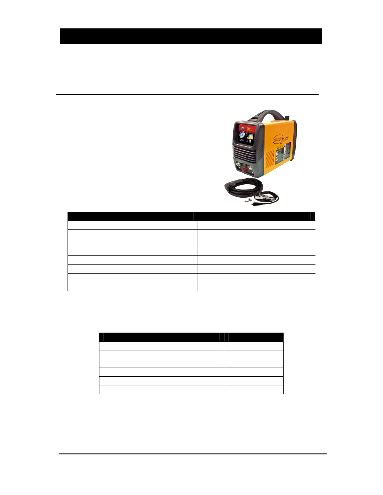
The Plasma 275 is an IGBT inverter
plasma cutter with thermal overload
protection, a Trafimet torch and a built-in gas
regulator. This easy to use plasma cutter has
the power to cut up to 1/8 in. materials and a
pilot arc that makes cutting expanded metal
possible. This machine required single-phase
120V , 60 Hz input power.
Specifications and Dimensions
DESCRIPTION SPECIFICATION
Power Supply 1ph-120V-60HZ
No-load Voltage 320V
Output Range 16A
Duty Cycle 50% @ 16A
Air Pressure 4.5 CFM@ 60 PSI
Power Switch 125VAC 20Amps
Dimension (L x W x H) 17.7”x6.7”x9”
Weight 21 lbs
Removing from carton
1.1 Remove cartons, bags or Styrofoam containing the welder and accessories.
1.2 Check the contents with the packing list below.
1.3 After unpacking unit, inspect carefully for any damage that may have
occurred during transit. Check for loose, missing, or damaged parts. Shipping
damage claim must be filed with carrier.
ITEM QTY.
Plasma Cutter 1 unit
Grounding Cable 1 pc
TRAFIMET Cutting Torch 1 pc
Electrode 3 pcs
Nozzle 3 pcs
Operator’s Manual 1set
″
2
Plasma Cutter
O
p
eratin
g
Instructions and Parts Manual
Plasma Cutter
Plasma 275
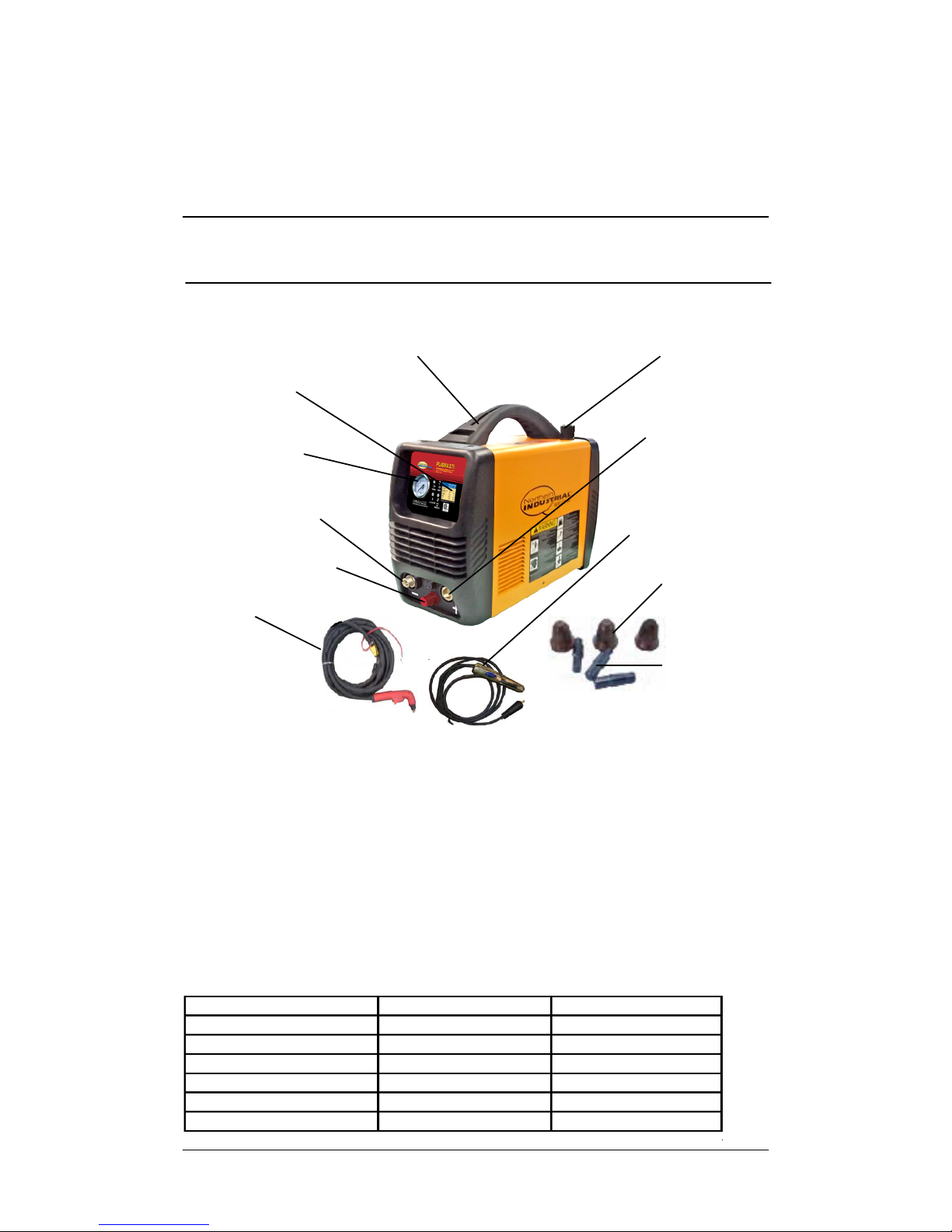
Know your Welder
Gas Pressure Display
The built-in gas display is used for reading the output gas pressure when cutting.
Gas Pressure Adjustor
It is used for adjusting the gas pressure. The gas pressure can be read from the
gas pressure display on the front panel. Normally, the pressure should be
adjusted between 55-90psi.
When cutting, this light is on to show the unit is on working mode.
Work Indicator
Cutting Chart
Handle
Gas Pressure
Cutting chart
Display
Gas Pressure
Adjustor
Connector for
Cutting Torch
Connector for
Grounding Cable
Connector for Torch
Arc Starting Cable
Cutting Torch
Grounding Cable
with Clamp
Nozzle
Electrode
This chart indicates the thickness of different types of materials that .
this unit can cut at a rate of 10 inches per minute.It also shows sever capacity.
Sever thicknesses may take more time than 10 inches per minute
Material Clean cut Sever
Mild steel 5/32″ 1/4″
Stainless steel 1/8″ 3/16″
Galvanized 1/8″ 5/32″
Aluminum 3/32″ 1/8″
Copper 1/16″ 3/32″
Brass 1/16″ 3/32″

3
Plasma Cutter
O
p
eratin
g
Instructions and Parts Manual
Plasma Cutter
Plasma 275
Low Gas Indicator Light
This light will be on when the gas flow is low.
Ground Cable Connection
Connect the ground cable to the postive (+) receptacle on the front of the plasma
cutter. The ground cable clamp connects to your work piece.
Torch Control Cable Connection
The black cable on the torch connects to the 3-Prong receptacle on the front of
the machine. Push on to snap in place. This is the control cable for the torch.
Torch Arc Starting Cable Connection
This connector is for the red cable of the torch. It is used to help the arc starting.
Torch Connection
Connect the torch to the negative (-) receptacle.
Protection indicator Light
When the unit is in thermal overload, is over voltage or lacking voltage, the
indicator will be on and the machine will stop working. When the unit is cooled
down and voltage stabilizes, the unit will return to work automatically.
Power indicator Light
This light will turn on when the input power cord is plugged into the power supply
and the power switch on the back of the plasma cutter is in the "ON" position.
Gas Hose Connection
The gas hose connection is on the back panel of the plasma cutter. This
connections requires a 1/4 inch NPT connection (Not supplied). The other end of
the gas hose connects to an air compressor or compressed air supply.
Power switch
It is the on/off switch. After the machine is connected to the input power supply,
turn on this switch. The power indicator on the front panel will turn on.
Power cord
Specification Table
The specification table is located on the back panel of the plasma cutter. The
Serial Number of this unit is listed on the specification table.
General Safety Information
1.1 Your Welding/Cutting Environment
-Keep the environment that you will be we
Plug this unit into a grounded 20 Amp 120V Circuit
lding/cutting in free from flammable
materials.
-Always keep a fire extinguisher within reach.
-Always have a qualified person install and operate this equipment.
-Make sure the area is clean, dry and well ventilated. Do not operate the plasma
cutter in humid, wet or poorly ventilated areas.
-Always have your plasma cutter maintained by a qualified technician in
accordance with local, state and national codes.
4
Plasma Cutter
O
p
eratin
g
Instructions and Parts Manual
Plasma Cutter
Plasma 275
-Always be aware of your work environment. Be sure to keep other people,
especially children, away from you while you are cutting.
-Keep harmful arc rays shielded from the view of others.
-Mount the plasma cutter on a secure bench or cart that will keep the welder
secure and prevent it from tipping over or falling.
1.2 Your Plasma Cutter’s Condition
-Check all cables, power cord and torch to be sure the insulation is not damaged.
Always replace or repair damaged components before using the plasma cutter.
-Check all components to ensure they are clean and in good operating condition
before use.
1.3 Use of Your Plasma Cutter
Do not operate the plasma cutter if the torch is wet. Do not immerse the plasma
torch. Do not stand in water while using this plasma cutter. These components
and the plasma cutter must be completely dry before attempting to use it.
-Follow the instructions in this manual.
-Keep the plasma cutter in the off position when not in use.
-Connect ground lead as close to the area being cut as possible to ensure a
good ground.
-Do not allow any body part to come in contact with the material being cut, or to
the ground or electrode from another plasma cutter or welder.
-Do not cut if you are in an awkward position. Always have a secure stance while
cutting to prevent accidents. Wear a safety harness if working above ground.
-Do not drape cables over or around your body.
- Wear eye protection (see ANSI Z49.1 safety standard) while cutting to protect
your eyes from harmful UV and IR ray’s.
-Wear proper gloves and protective clothing to prevent your skin from being
exposed to hot metals, UV and IR rays.
-Do not overuse or overheat your plasma cutter. Allow proper cooling time
between duty cycles.
-Keep hands and fingers away from moving parts.
- Do not point the Plasma torch at any body part or at anyone else.
-Always use this plasma cutter in the rated duty cycle to prevent excessive heat
and failure.
1.4 Specific Areas of Danger,
Caution or Warning
Electrical Shock
Plasma cutters can produce a shock that can cause injury or death.
Touching electrically live parts can cause fatal shocks and severe
burns. While cutting, all metal components connected to the wire
are electrically hot. Poor ground connections are a hazard, so secure the ground
lead before cutting.
-Wear dry protective apparel: coat, shirt, gloves and insulated footwear.
Table of contents
Popular Welding System manuals by other brands


Hobart Welding Products
Hobart Welding Products AirForce 375 owner's manual

GF
GF MSA 330 instruction manual

Hakko Electronics
Hakko Electronics FX-888D instruction manual

Abicor Binzel
Abicor Binzel ABIPLAS WELD 100 W operating instructions

EWM
EWM Taurus 355 Basic TDM operating instructions

Thermal Dynamics
Thermal Dynamics PakMaster 100 XL plus operating manual


