Nova Technology International, LLC RX-200 User manual

RX-200 User’s Manual
205A W. Hanover Rd. • PO Box 1357 • Graham, NC 27253 USA
(336) 513-5200 • US Toll-free (800) 794-6682
Fax (336) 513-5213 • info@thewebcutter.com
www.thewebcutter.com
Copyright © 2017 NOVA TECH International, LLC All rights reserved.
CONTENTS
Set-up ................................2
Quickstart ..........................4
Operation...........................5
Components.......................6
Touchscreens......................8
Operating Principle ..........12
Maintenance....................13
Trouble Shooting..............14
Spare Parts.......................18
Appendix..........................19

RX-200 Set-Up
1
2
2
3
4
• Check that all plastic air lines are connected.
• Connect the two M12 cable connectors to the
sockets under the air regulator. The connectors
are different and will only t the proper socket.
Align the pins in the socket with the groove in the
connector; press in and tighten. (PHOTO 1)
• Connect the main power cable to the main power
socket on the front of the machine and connect
the air pressure to the quick connector. (PHOTO
2) Use only the three pronged GROUNDED power
supply cord supplied. DO NOT OPERATE this
machine with the incorrect voltage, power cord or
with an extension cord.
• For HOT KNIFE models, connect the auxiliary
power cord on the cutting module to either one
of the power sockets on the side of the machine.
(PHOTO 3)
• The required air pressure is 80 - 120 psi. according
to the gauge on the back of the machine. To set
the pressure, pull and rotate the knob on the Air
Regulator until it displays the required operating
air pressure after connecting the air supply.
(PHOTO 4)

RX-200 Set-Up
3
5
6
7
• Set the webbing into the Reel Holder.
(PHOTO 5)
• The roller spring tension is set with the ball-
chain and chain clips. NOTE: changing the spring
tension after setting the cut length can change
the length of the cut pieces. (PHOTO 6)
• Feed the webbing through the center of the
rollers and adjust the magnetic guides. Move
and lock the Material Sensor over the center of
the material with the thumbscrew as shown.
(PHOTO 7) The red sensor light should be
on the material and the yellow light marked
“OUT” on the sensor should be OFF. Sensors are
adjusted during manufacturing and should not
need further adjustment. However, these sensors
are sensitive to contrast and may need further
adjustment. (See Appendix 8 for more details on
adjusted the Material Sensor)
• Push the webbing into the machine until it
touches the Feed Rollers. Turn on the main
power switch.

RX-200 Quickstart
4
8
9
10
11
OPERATION
• Turn on the main power switch located on the
front panel of the machine. (PHOTO 8)
For hot knife cutting modules, connect the
auxiliary power supply plug to either one of the
two Auxiliary Sockets (PHOTO 9) and turn on the
heater power switch.
Allow several minutes for the operating system to
start and for the hot knife to reach the operating
temperature. (PHOTO 10)
The hot knife temperature is set by pressing the up
or down arrows on the heat controller. Ensure the
fan is running before connecting an exhaust hose
to the fan housing.
The Main Screen should be visible when the system
is ready. (PHOTO 11)
• Set the feed roller pressure by pulling the ball-
chain over the slotted catch on the arm. Maintain
enough feed roller pressure to prevent the material
from slipping. Changing the roller tension before
setting the length since overall cut lengths can
change with different roller pressures.
• Press and hold the blue JOG button. The webbing
should feed through the rollers and into the
Cutting Module. When the end of the webbing
has exited the Cutting Module, press and hold the
yellow CUT button to cut. When the material cuts
cleanly, the machine is ready to be programmed for
automatic operation.

RX-200 Operation
5
PROGRAMMING
Toggle between US units (inches) and Metric units
(millimeters) by touching the Toggle Switch. You
may freely toggle between these two systems
without losing any entered data.
To set the required length, press the black LENGTH
display. Enter the length in the popup numerical
keypad. For inches, enter lengths to the nearest
hundredths of an inch (2 decimals). (Since the
system operates in millimeters, it will automatically
round all INCH length settings to the nearest
millimeter). For metric, enter the lengths to the
nearest millimeter. Press enter (ENT) when nished.
To set the required quantity, press the black QTY
display box. Enter the required number of cut
pieces into the pop-up numerical keypad. Press
enter enter (ENT) when nished.
Run a few test pieces to ensure that the program
settings are correct. To do this, press the green RUN
button. The machine should now measure and cut
automatically. Press the red STOP button at any
time to immediately stop the program. (Pressing
the green PAUSE button will stop the measuring
cycle without losing the length setting).
Check that the measured lengths correct. If not,
add or subtract a small amount to the length
setting. For problems with length setting or length
variation, see Troubleshooting.
A clean cut is achieved by the correct balance of air
pressure, cutting dwell time, and knife temperature.
For cutting dwell time adjustments, see the section
on TOUCHSCREENS. For problems in cutting, see
Troubleshooting.
Once the length is set correctly and the cutting
adjustments are acceptable, the machine is ready to
run automatically. Press the RESET COUNT button
to set the count to zero. Press the STOP button to
clear the last length.

OVERALL
Refer to the images shown for the location of the machine
components described below. Due to the many models
available, not all machines will look identical.
TOUCHSCREEN
There are several user screens available for operation,
settings and saving programs. The HOME or MAIN screen will
appear upon startup and from where most user settings are
made. The touchscreen may be activated by nger or stylus.
INDEXER
The Indexer (PHOTO 12) is the main part of the machine
that contains the controls and measures the webbing.
It consists of the red & black chassis, internal control
circuits (controller, drivers and power supplies), length
motor, feed rollers, and end sensor, air regulator and air
valves, emergency stop button, and external connections
and communications ports (USB and/or Ethernet). Indexer
Modules are congured during manufacturing to operate
from either left-to-right or right-to-left. Do not attempt to
change the feed direction of the indexer. The Index also
houses the interchangeable Cutting Module.
RX-200 Components
6
12
13
CUTTING MODULE
The interchangeable Cutting Module (PHOTO 13) is the
aluminum-framed unit that contains the knife assembly, each
with its own model sufx. There are several common types,
such as:
• SCL 5”/130mm hot knife
• GSL 6”/150mm guillotine
• USL 5”/125mm ultrasonic,
• AS3 3”/76mm alternating angle hot knife
• S3L 5”/125mm xed angle hot knife
• ASL 5”/130mm alternating angle hot knife
• G33 2.5”/60mm xed angle guillotine
• GAL 6”/150mm alternating angle guillotine
(many other types are also available)
The Cutting Module typically consists of the knife, air
cylinder(s), knife position sensors, as well as optional
components such as rotating actuators, air assist nozzles and
valves, special sensors, and pneumatic speed regulators. The
cutting module can be a standard type or one that has been
custom designed for a special application. Cutting modules
are easily interchangeable and additional cutting modules
can be used to expand the capacity and functionality of the
cutting machine.

RX-200 Components
7
14
15
16
Removing the Cutting Module: Disconnect the power
and data cables. Loosen the lock screws on either side.
(PHOTO 14)
Pull the cutting module UP and outward to remove.
(PHOTO 15)
REEL HOLDER
The Reel Holder (PHOTO 16) is a stand-alone device
designed to hold material on the most commonly
sized spools and rolls. Custom and oversized holders
are also available if needed.

MAIN SCREEN
The rst screen you will see upon starting (PHOTO 17).
The Main Screen contains the following screen elements and function descriptions:
RX-200 Touchscreens
8
17

RUN: Cut Cycle Initiates the automatic cutting cycle based on the settings entered.
STOP: Cut Cycle Stops automatic cutting cycle and clears the measured length.
CUT: Press and hold to activate the pneumatic knife.
JOG: Press and hold to feed the material into the machine.
RESET: Resets the quantity count.
PAUSE: Pauses the length motor during the measuring cycle WITHOUT LOSS
OF LENGTH. Pressing Pause again resumes the measured length.
Units Touch the toggle switch to shift from inches (0.01”) to metric (mm).
Metric (---> Inches:
LENGTH setting: Press the black display box to enter the desired length. (Inch units will be
automatically rounded to the nearest millimeter)
Length status: Under the Length setting display. Actively displays the length as it is being
measured. Pressing STOP will reset to 0.00; pressing PAUSE will retain the
active length.
QTY: Press the black display box to enter the TOTAL desired quantity.
Count: Under the COUNT display. Actively displays the quantity of pieces that have
been cut. (Note: count multiplier will double or triple the count based on
the advanced multiples setting)
Initial State: Status Actively displays the current operation and status of the machine.
Stop Ind.: When lighted, the blue lamp indicates that the machine has run out of
material, or that a wired safety guard or cover has opened.
Knife Position: Indicates the position of the knife. Yellow indicates the knife is in the home
position; red indicates the knife is in the cut position. At least one of these
should always be lighted.
Gears: Pressing the gears enters the Advanced Settings Screen.
RX-200 Touchscreens
9

RX-200 Touchscreens
10
18
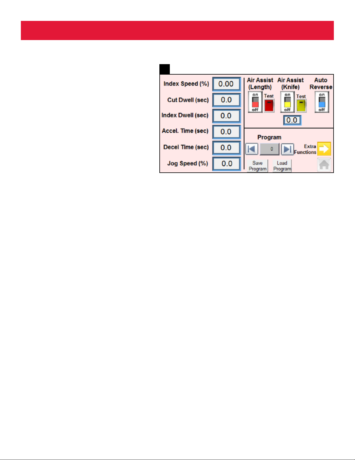
ADVANCED SETTINGS SCREEN
The Advanced Setting screen (PHOTO 18) is used for
changing dwell settings, motor ramp and jog speeds,
air assist settings (when equipped), motor auto
reverse, and program saving. The Advanced Settings
Screen contains the following elements and function
descriptions:
Index Speed (%): Sets the maximum length motor
speed in percent (1% - 100%).
Cut Dwell (sec): Sets the cutting dwell time (in
seconds) for cutting through the material. Light
materials require less time than heavy materials.
Index Dwell (sec): Sets the dwell time (in seconds)
between from the end of the cut cycle to the
measuring of the next length. This setting allows a
melted end to cool.
Accel. Time (sec): Sets the time (in seconds) for the
motor to accelerate to full speed. A longer Accel Time
will allow the length motor to accelerate more slowly
and minimize roller slip, to improve length accuracy,
especially on heavy rolls or with elastic materials.
Decel. Time (sec): Sets the time (in seconds) for the
motor to decelerate before cutting. A longer Decel
Time will minimize material overfeed of heavy or stiff
materials.
Jog Speed (%): Sets the motor speed when the JOG
button is pressed on the main screen.
Air Assist (Length): (red switch & test button) An
optional function that uses compressed air to assist
the measuring of very lightweight and imsy materials.
When equipped with an air assist valve the air nozzle
will emit a blast of air through the knife to prevent
jamming and sticking of the material. Pressing the red
Test button will momentarily activate the air assist
valve.
Air Assist (Knife): (yellow switch & test button) An optional
function that uses compressed air to assist the removal of cut
material from the knife or anvil. When equipped with an air assist
valve the air nozzle will emit a blast of air off the knife. This
function has a dwell time setting below the yellow switch. Pressing
the yellow Test button will momentarily activate the air assist valve.
Auto Reverse: (blue switch) When activated, this function will
cause the feed roller to reverse briey before measuring. This allows
the motor to remove material that might have adhered to the anvil.
If the machine experiences jamming in the knife area, turn this
function on.
Program: (with left and right arrows) Program (recipe) settings
may be saved by pressing the gray Save Program button. To run a
previously saved program (recipe), toggle to the program number
using the arrows and press Load Program. Programs are saved by
number only. For detailed instructions, see the Appendix.
Home: (gray house) - Press the home button to return to the main
screen.
Extra Functions: (yellow arrow) advances to the Additional
Functions Screen

RX-200 Touchscreens
11
ADDITIONAL FUNCTIONS
SCREEN
The Additional Functions screen (PHOTO 19) is used
for activating some standard functions such as One
Shot and Quantity Multiples. When equipped, this
screen activates optional machine functions such as
Alternating Angle Cutting, Registration cutting (using a
photocell), Batch Cutting, and Marking. The Additional
Functions Screen contains the following elements and
Standard Function descriptions (for Optional Functions,
please see the appendix).
One Shot Operation: (red three-way switch) -
When equipped with a One Shot Switch (foot pedal or
button) and activated, this function will allow the user
to measure and cut one piece at a time on demand.
The machine will stop after cutting (After Cut) or after
measuring (After Index). The default value is OFF.
Quantity Multiples: (red three-way switch) - This
setting multiplies the COUNT and QTY display on the
main screen to double or triple the count and quantity
when cutting more than one piece of material at
a time. Note: When used in multiples, the quantity
setting must be in multiples of either 2 or 3. For
example, when running 3 pieces at a time, the quantity
setting must be 3, 6, 9, 12, etc. The machine will then
display the total number of pieces cut. The default
value is 1.
Alternating Angle: (red three-way switch) - For alternating angle
models only. See Appendix 5 for details on the operation of this
function.
The Photo Registration, Batch Cutting and Cut & Mark Functions
activated from this screen. The default values are OFF. Press the
yellow arrow to the right of each function switch to enter the
programming screen for that function. Each of these screens have
their own instructions for operation.
Press the Additional Function Defaults RESET button to reset these
to default values.
19

Operating Principle
20
12
This cutting machine is designed to measure and
cut to length various types of narrow fabrics, lm,
metal strip, cord, wire, tubing, braids, and similar
materials. Measuring is accomplished by pinching
the material through two rollers held together
tightly by adjustable springs. The bottom roller is
driven via exible belt by a powerful computer-
controlled stepping motor. After leaving the rollers,
the material enters a cutting module containing
the knife, usually driven by an air cylinder and
compressed air. Upon cutting, the material should
fall away freely.
Virtually all functions of the motor and knife
are adjustable, such as speed, acceleration,
deceleration, dwell times, roller pressure, knife
pressure and assist devices, such as air nozzles,
and are all centrally controlled by a small computer
(PLC). The PLC is connected to directly to the
touchscreen. In some cases, the computer may
be connected directly to an outside network for
remote control or monitoring via an Ethernet
socket. (PHOTO 20) For details on conguring the
machine to a network, see the Appendix.
Data that is entered by the user to run the machine
is referred to as a “recipe” or “program.” Both
terms may be used interchangeably. User recipes
may be saved in the internal memory for future use.
For applications that may require a large quantity
of recipes, such as automatic marking, additional
memory may accessed from an external USB drive
via an optional external USB port. (PHOTO 20) For
details on using USB memory, see the Appendix.

Maintenance
21
13
The following should be checked periodically or as
needed following troubleshooting:
• Drive Belt: A belt too loose will produce
variation in lengths. To tighten, remove the
magnetic Feed Plate and locate the stepping
Drive Motor. Loosen the four hex head screws on
the Motor Bracket and pull back gently on the
motor to tighten the belt. (PHOTO 21)
• Drive Rollers: keeping the drive rollers clean
and free of material debris will ensure accurate
lengths. Clean the lower (steel knurled) roller
with a small brass wire brush to remove
material from the roller grooves. Clean the
lower (aluminum sandpaper) roller by replacing
the black adhesive sandpaper cover when it
becomes too worn. The roller may not need to
be removed to change the covering. Clean the
upper (rubber) roller with rubbing alcohol or
mild solvent. If the top roller does not turn freely,
apply light oil or remove the roller and clean the
bronze bearings.
• Hot Knife and Anvil (hot knife models only):
Clean the anvil when residue buildup causes
material to adhere to the anvil which can result
in jamming. Hot Knives generally need no
maintenance or cleaning as a properly set and
tuned hot knife will burn away excess residue
between cut cycles. For auto-tune details and
anvil cleaning refer to the separate instructions
supplied for the Hot Knife Cut Module being
used.
For guillotine models, periodic cleaning may
be required to remove adhesive or other reside
from the material being cut. For cleaning and
resharpening, refer to the separate instructions
supplied for the Guillotine Module being used.
• Loose fasteners: periodically check for loose
or missing fasteners to ensure the proper
running of the machine. Unusual noise may be
the result of misalignment of parts due to loose
or missing fasteners. Virtually all fasteners are
metric.

The most common fault is typically associated with lengths or
length variation. It is important to know that these machines
are designed to measure and cut a wide variety of materials.
NOTE: Length variation should not be confused with
Incorrect Length. You should become familiar with this
difference before making any adjustments or repairs to the
machine.
LENGTH VARIATION
Length variation is the inconsistency of the cut lengths of
the same material running under the same recipe settings.
Variation can be caused by material that stretches or slips
between the feed rollers resulting from high inertia created
by pulling from a very heavy roll too quickly, for example. As
with every industrial process, a certain amount of variation
is normal. Normal variation typically falls in the range of
0.5% to 1% of the overall length, depending on many
variables such as material characteristics, roll size, friction,
and machine wear for example. Normal variation may still
be reduced further by changing machine settings or by
using additional equipment such as a Prefeed Device which
eliminates most inertial variation.
To nd out if the variation is normal, rst test the machine
without material. Set an index length of 500mm. Remove
the cutting module (but keep it connected to the air and M12
cable) and make a mark in an observable location the lower
roller and bearing mount. (PHOTO 22) Allow the machine
to run a few length cycles. The mark should return to the
same location. If
not, check the belt
tension as described
below.
If the machine is
measuring properly
from this test,
run a few short
pieces with the
material under
minimal tension. If
this process reduces the variation then go to the Advanced
Settings Screen and increase the Acceleration Time to allow
the length motor to accelerate more slowly, or reduce the
Index Speed. This may correct the problem. Additionally, the
problem can be corrected and the machine can be operated
at higher speeds with the use of a Prefeed Device.
If variation persists with consistent material tension, then
check the following:
• Drive belt tension should be snug, not loose. Remove
the Infeed Plate and adjust the belt tension by loosening
the adjustment screws and moving the motor assembly.
(PHOTO 23) Retighten the screws.
• Incorrect spring tension can also cause variation in
lengths. Ensure that the spring tension holding the
rollers is sufcient and even. Adjust roller tension evenly
by moving the chain settings on the left & right roller
tensioners. NOTE: Changing roller tension may also
change the cut length.
• Roller Jamming or Binding can also cause length variation.
Lift the feed roller lever and rotate the top roller to ensure
it turns freely.
• With the power switch off, rotate the lower steel drive
roller by hand to ensure it turns freely. Check that feed
plates are not touching the steel roller.
Trouble Shooting
14
22
23

• The material should ow easily from the Reel Holder
through the end sensor and material guides. Check that
there is no binding or jamming of the material by pulling
it through the machine by hand. Adjust the magnetic
material guides so that there is a little clearance between
the material and the guides.
STOP INDICATOR LIGHT
The Stop Indicator Light on the Main Touchscreen will
indicate when a stop fault has occurred. Stop Faults can
occur when the Material Sensor has not detected material, or
any other device (such as optional jam detector, door switch,
etc). has been tripped. The Blue Stop Indicator will stay
lighted whenever any of these conditions occur. Pressing Stop
or Run will reset the Indicator.
The most common
cause for the Stop
Fault is the Material
Sensor. To determine
if the sensor is
creating a Stop
Fault, disconnect the
sensor by removing
the sensor plug
(PHOTO 24) and
run the machine. If
the machine runs
with the Sensor disconnected, consult Appendix 8 - NO
MATERIAL SENSOR ADJUSTMENT.
If you machine is equipped with any additional Stop Fault
sensors, check to be sure they are functioning properly.
Consult the manufacturer with Serial # and Model # for more
information on how your machine is equipped.
INCORRECT LENGTH
Incorrect length is a signicant difference in cut length from
the programmed length. This is normal as different types of
materials can have vastly different characteristics, such as
material elasticity, compression, slippage, atness, inertia,
and even from unseen inconsistencies in the material itself.
This can be corrected by changing some of the internal
machine settings. Be sure to save your recipe settings for
materials that are used regularly.
LENGTH MOTOR STOPS WORKING
If there is power to the touchscreen but the length motor
will not advance when pressing JOG, remove the main cover
screws and open the cover. Check rst that the Stepping
Motor Driver has power by observing the power lamp shown.
(PHOTO 25) If the Driver has power, check the Motor Fuse
in the gray fuse holder mounted on the DIN rail below
the Driver. (PHOTO 26) If the fuse is good, contact the
manufacturer for further assistance.
Trouble Shooting
15
24
25
26

MATERIAL JAMMING
Some materials may not feed through the machine
well due to elasticity, curl, imsiness, etc. The RX-
200 Series can be equipped with an OPTIONAL Air
Assist function to help move lightweight and imsy
material from the feed rollers through the cutting
area.
The Air Assist is toggled ON or OFF through the
Advanced Setting Window. If the machine is
equipped with an Air Assist Valve, ensure that the
Air Assist function is turned ON and that sufcient
air pressure is present during the measure to length
cycle. Press the red Air Assist Test button to test the
valve; you should hear the blowing of air while the
button is held. The Air Assist pressure is controlled
with the small ow control valve as shown.
(PHOTO 27)
Trouble Shooting
16
27
KNIFE NOT MOVING
The knife is operated by an air cylinder controlled
by an air valve. If the knife will not move when
pressing the CUT button on the main screen, check
the following:
• The yellow Knife Position indicator on the Main
Touchscreen should be ON; the red Knife Position
indicator should be OFF.
• There should be sufcient air pressure to the
machine (80psi minimum).
• Press the CUT button and observe if indicator
light on the air valve lights while holding the
button
• Check that the Knife Speed Flow Control valves
are not closed (PHOTO 27)
• Ensure that the air cylinder is not binding. Turn
the power off to the machine and manually
activate the air valve by pressing the Valve
Override button. (PHOTO 28)
28

NO DISPLAY ON
TOUCHSCREEN
The touchscreen is inactivated when the Emergency
Stop knob is pressed. To release, twist the Red knob
as shown by the arrows on the label.
• Check that the power supply plug is connected
to the touchscreen inside the main cover.
• Check that the 24V power supply is not faulty.
The green “DC ON” light should be lighted with
the power on (PHOTO 29)
• Check the main fuse on the front of the machine
(see next item)
NO POWER TO MACHINE
• Check that the main fuse. The main fuse is
located in the power inlet module on the front of
the machine. Use a small screwdriver to remove
the fuse drawer. (PHOTO 30) Replace with an
identical fuse.
• Check the Emergency Stop switch by rotating it
in the direction of the arrow.
CUTTING PROBLEMS
Cutting problems can vary with the type of cutting
module installed in the machine. For problems
relating to cutting, please refer to the Cutting
Module User Manual for your machine supplied
separately as an addendum to this manual.
OTHER FAILURES
For problems not covered, contact the manufacturer
for technical service. The machine may need to be
returned for service of serious failures or repairs.
Trouble Shooting
29
30
17

18
Parts vary by model type, voltage, and optional
features. For most common spare parts, please
contact the manufacturer. Please have the machine
MODEL NUMBER and SERIAL NUMBER located near
the main power supply. (PHOTO 31)
Spare Parts
31
NOTES
_________________________________________________________________________________________________
_________________________________________________________________________________________________
_________________________________________________________________________________________________
_________________________________________________________________________________________________
_________________________________________________________________________________________________
_________________________________________________________________________________________________
_________________________________________________________________________________________________
_________________________________________________________________________________________________
_________________________________________________________________________________________________
_________________________________________________________________________________________________
_________________________________________________________________________________________________
_________________________________________________________________________________________________
_________________________________________________________________________________________________
_________________________________________________________________________________________________
_________________________________________________________________________________________________

19
Appendix 1:
Saving & Recalling Program Recipes
Program recipes can be saved to internal (or external)
memory for future recall. Program recipes are saved
numerically for reasons to be outlined later. Internal memory
allows up to 60 recipes to be saved. Additional recipes may
be saved to a memory stick via the optional external USB
port when equipped. (see Appendix 7 for more details)
SAVING A PROGRAM
• To save a current program go to the Advanced Settings
Screen from the Main Screen by pressing the small gears
icon.
• Pressing the gray Save Program at the bottom of the
screen will save all the program recipe data in the memory
location numbered under Program.
RECALLING A PROGRAM
• To recall a program go to the Advanced Settings Screen
from the Main Screen by pressing the small gears icon.
• Previously saved programs are numbered inside the gray
box under Program. Toggle through all saved programs by
pressing the LEFT ç or RIGHT è arrow buttons on each
side of the Program Number box.
• Select the program to be recalled.
• Press “Load Program” and the program is now ready to
run. Press the Home button to return to the Main Screen
and run the recalled program.
Appendix 2:
Photo Registration Cutting
Photo Registration Cutting allows the machine to cut
directly on a mark, or at a point relative to a mark on the
material. Machine accuracy is now limited to the accuracy
of the printing. YOUR MACHINE MUST BE FITTED WITH AN
OPTIONAL REGISTRATION CONTRAST or PHOTO-SENSOR
IN PLACE OF THE END-OF-MATERIAL SENSOR SUPPLIED.
The Photo-Sensor connects in place of the End-Of-Material
Sensor using the 4-pin connector socket. When programmed
correctly, the photo-sensor will search the webbing as it is
being measured for the required cut registration mark. Upon
locating the mark, the machine will stop and cut, or continue
to index further according to the user settings.
Refer to the illustration (PHOTO 32). The programming
sequence is as follows from the Photo Registration Settings
screen:
Index Length: Overall length between Registration Marks
minus approx. 1/2 of the Search Window length. The Sensor
will ignore any detections, such as logos, marks, color
changes, etc. in this distance.
Search Window: Search distance clear of any contrast
marks that might confuse the sensor. Allow a setting that
allows for a reasonable variation in registration mark
location. If the registration mark is not found within this
window, the machine will stop and return a Photo Reg Error
on the touchscreen. A window too small or too large can
result in Registration errors.
Offset Length: Once the registration mark has been
located, the machine will measure this additional distance to
position the mark under the knife.
Search Speed: This is a percentage (%) of the maximum
motor speed when running in the Search Window setting. A
slower speed setting (10-15%) will reduce the likelihood of
detection errors. Increase this speed as needed.
Jog Speed: This is a percentage (%) of the maximum motor
speed when the JOG button is pressed.
Sensor Signal: This indicator lamp will light when the
sensor has detected the mark and is creating an output
signal to the machine.
32

20
Teach In: Press this button to activate the “Teaching”
function of the installed sensor, if applicable. See the
operating instructions supplied by the sensor manufacturer
for the correct procedure for teaching the sensor.
Once these length parameters have been set, align the
registration or cut mark under the knife and press the
CUT button. The machine is now ready to operate under
Photo Registration Mode. The machine should perform the
following operation sequence:
1) Measure Index Length
2) Slow to the search speed while searching for the
registration mark
3) When the registration mark is detected, the machine will
index the programmed Offset Length and stop. If the
registration mark is not detected, the machine will return
a “Photo Reg Not Found” error.
For details on how to select, wire, install and use the correct
photo-sensor, contact the manufacturer for additional
instructions and technical assistance.
Appendix 3:
Batch Cutting
Batch Cutting mode is a process the machine uses to
measure and cut different length and quantity combinations
sequentially, which can maximize utilization of a limited
material supply or color batch, for example. The Batch Mode
setting is activated from the yellow Batch Cutting button
on the Additional Functions screen. (PHOTO 33) When
operating in Batch Cutting mode, the machine will run a
string of consecutive program recipes in a continuous loop.
With Batch Cutting turned ON, navigate to the Batch
Cutting Settings screen (PHOTO 34) to select the string of
SEQUENTIAL program recipes to run. Function descriptions
for Batch Cutting mode are as follows:
• First Program #: enter the number of the rst program
recipe in the batch sequence
• Last Program #: enter the number of the last program
recipe in the sequence
• Batch Count: enter the number of loops, or batch cycles to
run.
For example, if a product requires 5 pieces of webbing cut at
20”, 5 pieces cut at 6.5”, and 20 pieces at 50”, the program
number for these three program recipes must be saved and
numbered sequentially. The Batch Count would be the total
number of material batches to be cut.
Note: Program recipes may also be recalled from an external
memory device via an external USB stick when the machine
is so equipped. For more details, see Appendix 7: Accessing
Additional Memory via USB Port.
33
34
Table of contents