NOVACAT V10 ED Operational manual

Operator‘s manual
GB
+ INSTRUCTIONS FOR PRODUCT DELIVERY . . . Page 3
"Translation of the original Operating Manual" Nr. 99 3846.GB.80Q.1
• Disc mower
NOVACAT V10 ED/RC
(Type 3846 : + . . 01295)

1500_GB-PAGE 2
Product liability, information obligation
Product liability obliges manufacturers and dealers to issue operating instructions for the machine at the point of sale and to instruct
the customer on the operation, safety and maintenance regulations governing the machine.
A confirmation is required to verify that the machine and operating instructions have been handed over correctly.
For this purpose
- Document A is to be signed and returned to Pöttinger or via the internet to www.poettinger.at
- Document B remains with the specialist dealer handing over the machine.
- The customer receives document C.
For the purposes of product liability law, every farmer is an entrepreneur.
In the terms of product liability law, damage to property is any damage arising due to the machine, but not to the machine, and an
excess (500 euros) exists for this liability.
Corporate damage to property within the terms of the product liability law is excluded from this liability.
Be advised! The operating instructions must also be handed over with any subsequent machine sale or transfer and the transferee
must be instructed in the regulations stated.
Pöttinger - Trust creates AfÀnity - since 1871
"Quality pays for itself." Therefore we apply the highest quality standards to our products which are constantly monitored by our
in-house quality management and our management board. Because the safety, perfect function, highest quality and absolute
reliability of our machines in operation are the core competencies for which we stand.
There may be deviations between these instructions and the product as we are constantly developing our products. Therefore no
claims may be derived from the data, illustrations and descriptions. Please contact your Specialist Service Centre for any binding
information about specific features of your machine.
We would ask you to please understand that changes to the scope of supply with regard to form, equipment and technical
specifications are possible at any time.
Any form of reprint, translation or reproduction, including excerpts, requires the written approval of Pöttinger Landtechnik GmbH.
All rights according to copyright laws remain expressly reserved by Pöttinger Landtechnik GmbH.
© Pöttinger Landtechnik GmbH – 31st October 2012
Refer to PÖTPRO for additional information about your machine:
Are you looking for suitable accessories for your machine? No problem! All the information you require is here at your disposal.
Scan the QR code on the machine's type plate or look under www.poettinger.at/poetpro
And if we don't have what your looking for, then your Specialist Service Centre is there for you with help and advice.

Dokument D
GB-0600 Dokum D Anbaugeräte - 3 -
PÖTTINGER Landtechnik GmbH
Industriegelände 1
A-4710 Grieskirchen
Tel. 07248 / 600 -0
Telefax 07248 / 600-2511
TMachine checked according to delivery note. All attached parts removed. All safety equipment, drive shaft and operating
devices at hand.
TOperation and maintenance of machine and/or implement according to operating instructions explained to the customer.
TTyres checked re. correct pressure.
TWheel nuts checked re. tightness.
TDrive shaft cut to correct lenght.
TCorrect power-take-off speed indicated.
TFitting to tractor carried out: to three-point linkage
TTrial run carried out and no defects found.
TFunctions explained during trial run.
TPivoting in transporting and operating position explained.
TInformation given re. optional extras.
TAbsolute need to read the operating manual indicated.
Please check. X
According to the product liability please check the above mentioned items.
INSTRUCTIONS FOR
PRODUCT DELIVERY
GB
In order to prove that the machine and the operating manual have been properly delivered, a confirmation is necessary.
For this purpose please do the following:
- sign the document A and send it to the company Pöttinger or via the internet to www.poettinger.at
- document B stays with the specialist factory delivering the machine.
- document C stays with the customer.

- 4 -
TABLE OF CONTENTS
1601_GB-Inhalt_3846
GB
Attention!
Safety hints to
observe in
supplement!
Table of contents
WARNING SIGNS
CE sign ...................................................................... 5
Meaning of warning signs.......................................... 5
ATTACHING TO TRACTOR
Attaching machine to tractor..................................... 6
Attach connecting lines from the front mower. ......... 7
Establish an electrical connection to tractor ............ 7
Connect sensor cable from front mower................... 8
Detach cardan shaft ................................................. 8
Hydraulic connection................................................. 8
Note rotation direction of mower discs ..................... 9
TRANSPORT
Conversion from working position to transport
position.................................................................... 10
Raise to road transport position.............................. 10
Lower to field transport position.............................. 10
Driving on public roads............................................ 11
Transport position ................................................... 11
Parking position....................................................... 12
POWER CONTROL
Terminal performance features................................ 13
Initial start ................................................................ 13
Keys allocation ........................................................ 14
Menu tree................................................................. 15
Menus..................................................................... 16
Diagnosis function................................................... 27
ISOBUS TERMINAL
Operation structure - mower with ISObus solution. 30
Meaning of keys ...................................................... 31
Diagnosing function................................................. 35
Configuration menu ................................................. 36
Joystick - Mower configuration............................... 37
Setting the joystick .................................................. 37
OPERATION
Important notes prior to starting work..................... 38
Mowing.................................................................... 39
Reversing................................................................. 39
Anti-collision device................................................. 39
OPERATION
Working on slopes................................................... 40
ROLLER CONDITIONER
Safety advice ........................................................... 41
Operation mode....................................................... 41
Possible settings ..................................................... 42
Operation................................................................. 42
Maintenance ............................................................ 43
Roller conditioner for collector ................................ 46
Maintenance of the rotor tines:................................ 46
TINE CONDITIONER
Mowing with the conditioner ................................... 47
Rotor speed 700 rpm .............................................. 47
Correct V-belt tension ............................................. 47
Rotor tines: .............................................................. 47
Installing and removing the conditioner .................. 48
CONDITIONER
Mowing without Conditioner ................................... 51
SWATH DISCS
Swath Discs............................................................. 52
Flat cone conveyor (Optional extra)......................... 52
Safety advice ........................................................... 53
General maintenance information ........................... 53
Cleaning of machine parts....................................... 53
MAINTENANCE
Parking in the open.................................................. 53
Winter storage ......................................................... 53
Cardans ................................................................... 53
Hydraulic unit........................................................... 53
Cutter bar oil level check ....................................... 54
Oil change for cutter bar.......................................... 55
Maintaining the gearbox.......................................... 56
Maintenance of the mower articulated shafts ......... 57
Installing cutter blades ........................................... 58
Setting the field transport position (headlands FT).. 59
Checking wear on mowing blade holders ............... 60
Holder for a quick change of cutter blades............. 61
Checking the mowing blade suspension................. 61
Changing the Cutter Blades .................................... 61
ELECTRO-HYDRAULICS
Disruptions and remedies to power failure.............. 62
TECHNICAL DATA
Technical data ......................................................... 63
Necessary connections ........................................... 63
Position of Vehicle Identification Plate .................... 63
The defined use of the mower unit.......................... 64
SUPPLEMENT
Lubrication chart...................................................... 71
Lubricants................................................................ 73
SERVICE
Hydraulic plan.......................................................... 76
Electric circuit diagram............................................ 77
Electric circuit diagram (hydr. relief) ........................ 78
Processor ................................................................ 79
Signal socket connection cable............................... 80
Terminal (Power Control)......................................... 80
Repairs on the cutter bar......................................... 81
Combination of tractor and mounted implement .... 82

- 5 -
9700_GB-Warnbilder_361
GB
WARNING SIGNS
Stay clear of swinging area of implements
Close both side protective coverings before engaging
p.t.o..
Never reach into the crushing danger area as long as
parts may move.
CE sign
The CE sign, which is affixed by the manufacturer, indicates outwardly that this machine
conforms to the engineering guideline regulations and the other relevant EU guidelines.
EU Declaration of Conformity (see supplement)
By signing the EU Declaration of Conformity, the manufacturer declares that the machine being
brought into service complies with all relevant safety and health requirements.
Meaning of warning signs
Danger - flying objects; keep safe distance from the
machine as long as the engine is running.
Wait until all machine components have stopped
completely before touching them.
Stay clear of mower knife area as long as tractor engine
is running with PTO connected.
Shut off engine and remove key before performing
maintenance or repair work.
Recommendations
for work safety
All points referring
to satety in this
manual are
indicated by this
sign.
bsb 447 410
495.167
- 6 -
1500_GB-ATTACHING_3846
GB
ATTACHING TO TRACTOR
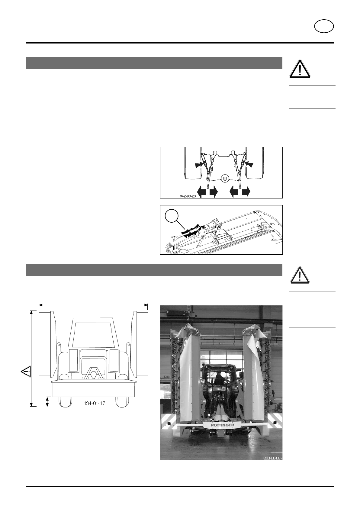
Attaching machine to tractor
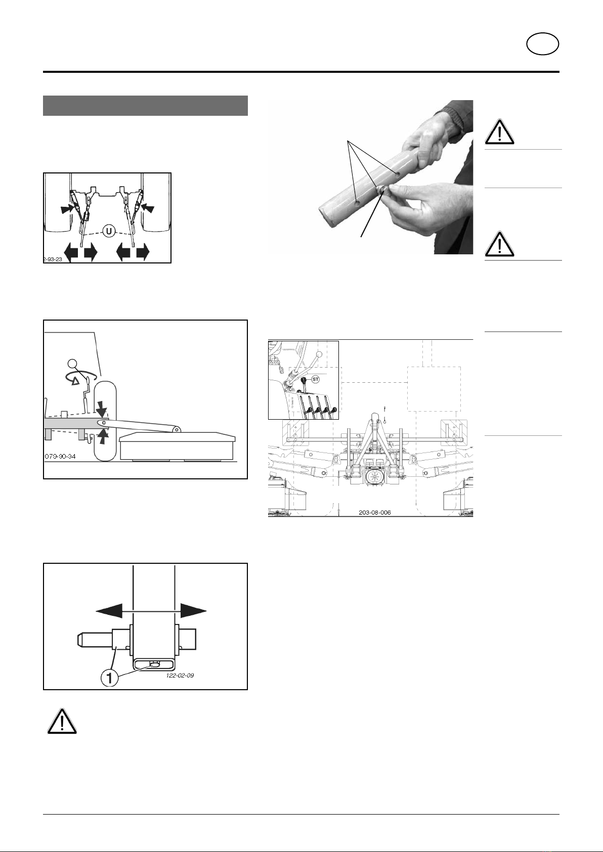
Attach mower centrically to tractor
- Adjust lower link accordingly.
- Secure the lower link so that the machine cannot swing
out sideways.
Mounting frame horizontal
- Bringmounting frametohorizontal position by adjusting
lower link jackscrew (15).
15
Pin machine to three-point mount
- Adjust lower link bolts (1) on bearing frame according
to the three-point category, and adjust track width using
thefixing screw.Mowermustnottouchreartractortyres.
Ensure fixing screw is inserted in required
hole (see figure below) on the bolt!
Otherwise mower may come loose from
coupling, fall to the ground and cause
damage to property.
Safety
hints:
see Supple-
ment-A1, 7.), 8a.
- 8h.)
Caution
This machine
is designed for
operation with a
tractor (not for
self-drive work
machines).
The driver’s visual
range is limited
with self-drive
work machines
when both outer
mower bars are
raised in the
transport posi-
tion.
3 drilled holes
Fixing screw
Setting lower link height
- Set tractor hydraulics (ST) using the depth stop.
This height makes an optimum levelling of the uneven
ground possible and does not need to be altered when
swivelling the cutter bars up.
825
- 7 -
1500_GB-ATTACHING_3846
GB
ATTACHING TO TRACTOR
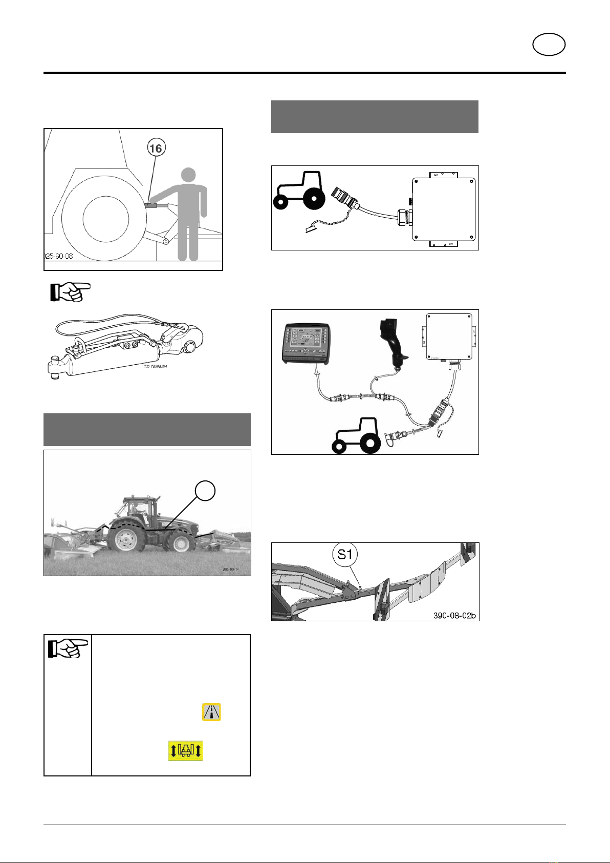
Adjust upper link spindle
- Turningupper link spindle(16) adjuststhe cutting height.
Ahydraulicupper linkis recommended
(double-acting control unit)
Attach connecting lines from the front
mower.
K
"Power Control" variant
With the “Power Control” variant, the possibility exists of
controlling the front mower's automatically folding side
protection along with the rear mower. (Optional extra)
Note:
The hydraulic hoses between front
mower and rear mower are pressurized.
These must be depressurized before
disconnecting.
Power Control Press key until
signal tone is heard (approx. 3 Sec)
ISOBus:Press key untilsignal
tone is heard (approx. 3 Sec)
Establish an electrical connection to
tractor
Operating unit on tractor with ISO Bus control
- Connect 9-pin ISO plug to ISO-Bus socket on tractor
473A2000.0
Operating unit on tractor without ISO Bus control
- Attach connection cable between 9-pin ISO plug and
3-pin socket DIN 9680 on tractor or operating unit
Lighting:
- Connect 7-pin plug to tractor
- Adjust lighting carrier position (S1)
- Clean and check that lighting on mower functions
properly.
- 8 -
1500_GB-ATTACHING_3846
GB
ATTACHING TO TRACTOR
Important!
Check the vehicle
for roadworthi-
ness prior to
every operation
(lights, brakes,
protective panels,
…)!
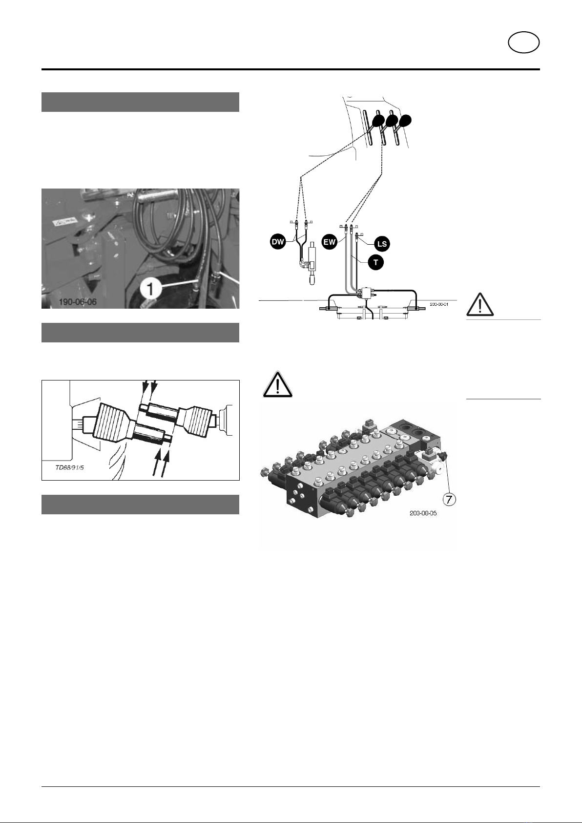
Connect sensor cable from front mower
Electrical cable connection between front mower
and mower combination
- 3-pin cable for sensor attachment kit (1)
(Starting from the back, lay sensor cable to tractor so
that the cable cannot become damaged e.g. tyres,
exhaust, ...)
Detach cardan shaft
- Before initial operation, check the cardan shaft length
and adapt if necessary. See chapter "Drive Shaft" in
Supplement B also.
Hydraulic connection
Minimum hydraulic system:
1 single-acting hydraulic circuit (EW) with depressurized
return flow (T)
Optimum hydraulic system:
1 single-acting hydraulic circuit (EW) with depressurized
return flow (T)
1 dual-acting hydraulic circuit (DW) for hydraulic upper link
or
1x Load sensing hydraulic circuit (LS) (Optional extra)
consisting of:
- single-action hydraulic circuit (EW)
- pressureless return (T)
- load sensing line
1 dual-acting hydraulic circuit (DW) for hydraulic upper link
Settings
The screw (7) on the hydraulic block must also be adjusted.
Be advised!
Separate electrical connection
For tractors with "Load sensing"
- Screw in screw (7) completely on hydraulic block
For tractors with a closed hydraulic system
- Screw in screw (7) completely on hydraulic block
For tractors with an open hydraulic system
- Unscrew screw (7) completely on hydraulic block

- 9 -
1500_GB-ATTACHING_3846
GB
ATTACHING TO TRACTOR
Note rotation direction of mower discs
- Select appropriate rotation direction for the drive
- If the necessary p.t.o. direction of rotation cannot be
selected from the tractor, then turn the gearing (G1)
180° .
180°
Be advised!
Before gearing is refitted to the machine:
1. Swapventilationscrewand drain plug.
2. Correct position for ventilation screw
is on the top.

- 10 -
1400_GB-TRANSPORT_3846
GB
TRANSPORT
Raise to road transport position
This key's function can only be activated when all mower
units are in field transport position (headland FT)
- Switch off drive and wait for complete stop.
- Swivel all hoop guards on mower in
Variant with "Power Control"
Briefly press key
the function is activated
Press key
all mower units swivel to end position
Variant with "ISOBus-Terminal"
Press softkey to open Transport menu.
Briefly press softkey
the function is activated
Press softkey
all mower units swivel to end position
• Before swivelling cutter bar up, switch
off drive and wait for mower discs to
completely stop.
• Ensure that swivel range is clear and that
no-one is standing in the danger area.
Conversion from working position to transport position
Safety advice!
Carry out change
from working po-
sition to transport
position only on
even, firm ground.
• Move implement
only in transport
position!
Lower to field transport position
Variant with "Power Control"
Briefly press key
the function is activated
Press key
all mower units swivel to field transport position (FT)
Variant mit "ISOBUS-Terminal"
Press softkey to open Transport menu.
Briefly press softkey
the function is activated
Presssoftkey
all mower units swivel to field transport position (FT)
- Swivel all guard hoops on mower out
- 11 -
1400_GB-TRANSPORT_3846
GB
TRANSPORT
Transport position
Driving on public roads
- Observe the official regulations of your state/country.
• Travel on public roads only in the transport position.
• Safety devices must be in proper condition.
• Before travelling, bring swivelling parts to correct position and secure against dangerous position changes.
• Check that lighting functions before travelling.
• Important information is also available in the supplement to this operator's manual.
Hydraulic lower link
- Secure hydraulic lower link so that implement cannot
swing out sideways.
Transport safeguard (Ts)
- Check transport safeguard before travelling!
Check that both mower units are properly secured with
safety hooks!
max. 4000
200
3500
3000
Be advised!
Be aware of max.
permissible trans-
port height (4 m)!
Be advised!
Parking the
machine in the
transport position
is not permitted.
Danger of tipping!
161-09-04
Ts

- 12 -
1000_GB-ABSTELLPOS_3846
GB
PARKING POSITION
Parking position
Caution!
Only park the mower combination in the
working position (both mower units are
folded down). Maximum danger of tipping
over if the mower combination is parked
in the transport position.
278-09-16
Safety note:
Only park the disc
mower on firm,
level ground and
ensure a secure
position.

- 13 -
1400_GB-Power Control_3843
GB
POWER CONTROL
Terminal performance features
Connection to power
The power supply for the entire electronic system (job calculator and terminal) is conducted through a plug (compliant
with DIN 9680) from the tractor's 12V onboard electrical system. These three-pin plugs may also be two-pin versions as
only two main wires (+12 V, ground) are required.
Be advised!
Other plug and socket designs are not permitted otherwise functional reliability cannot be assured.
Technical data
Operating voltage: +10V / +15V
Operating temperature range: -20°C +60°C
Storage temperature: -30°C +70°C
Degree of protection: IP65
Fuse: 10A multifuse in an operating voltage plug
Function
All of the attached unit's functions can be directly controlled through the Power Control Terminal. In addition, the Power
Control Terminal has a large display to indicate the current operating condition, various menus and alarm reports. A
prerequisite is a single-acting hydraulic circuit with depressurised return or load sensing.
Operating with the Power Control Terminal
1. Position PowerControlTerminal in tractorcabin
where it can be clearly seen. (To secure the
terminal there is a holder on the reverse side.
2. Connect terminal to tractor cable with plug 1.
3. Run job calculator cable from implement to
tractor cabin and connect to tractor cable via
theISObusplug (2). (Makesurethatthecables
are properly arranged!)
4. Plug the tractor cable plug (3) in to the tractor's
12V power supply.
5. If hectare counting is required, connect cable
with plug (4) to socket in tractor (DIN 11786)
and job calculator's cable harness.
To activate terminal, press key "I/O" .
To deactivate terminal, press key "I/O" for
three seconds.
Note!
Do not leave the
control terminal
out in the weath-
er.
ISObus
plug 2
Tractor cable
with ISObus
Power
Control
Terminal
10 Amp fuse
ISObus-capable job
calculator
Plug 4
with
Tractor socket (DIN
11786)
Plug 3
Plug 1
Initial start
- 14 -
1400_GB-Power Control_3843
POWER CONTROL GB
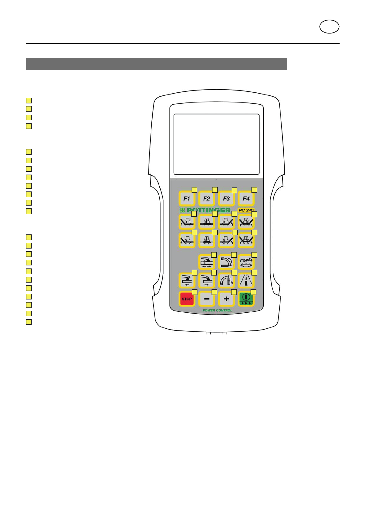
Keys allocation
a b d
fh
c
eg
i j k l
onm
qp r s
wvut
Function keys
aFunction key 1*
bFunction key 2*
cFunction key 3*
dFunction key 4*
Raising and lowering the mower unit
eRaise left mower unit
fRaise front mower unit
gRaise right mower unit
hRaise all mower units
iLower left mower unit
jLower front mower unit
kLower right mower unit
lLower all mower units
Side shift, cross conveyor, transport
mSlope travel preselection
nRaise cross conveyor
oChange cross conveyor belt speed
pDecrease working width
qIncrease working width
rLower cross conveyor
sRoad transport preselection
tStop - stops every required function
uDecrease value of a setting
vIncrease value of a setting
wOn/Off
Press [On/Off] key to switch on Power
Control Terminal. Press [On/Off] key to
open up System Menu.
Press and hold [On/Off] key longer to
switch off Power Control terminal.
* Function keys have different functions depending
on the menu.

- 15 -
1400_GB-Power Control_3843
POWER CONTROL GB
Menu tree
V10
V10
X8
X8
M1
M2 M3
M7
M6
M3
M4 M5
Press and hold for 10 seconds!
- 16 -
1400_GB-Power Control_3843
POWER CONTROL GB
Menus
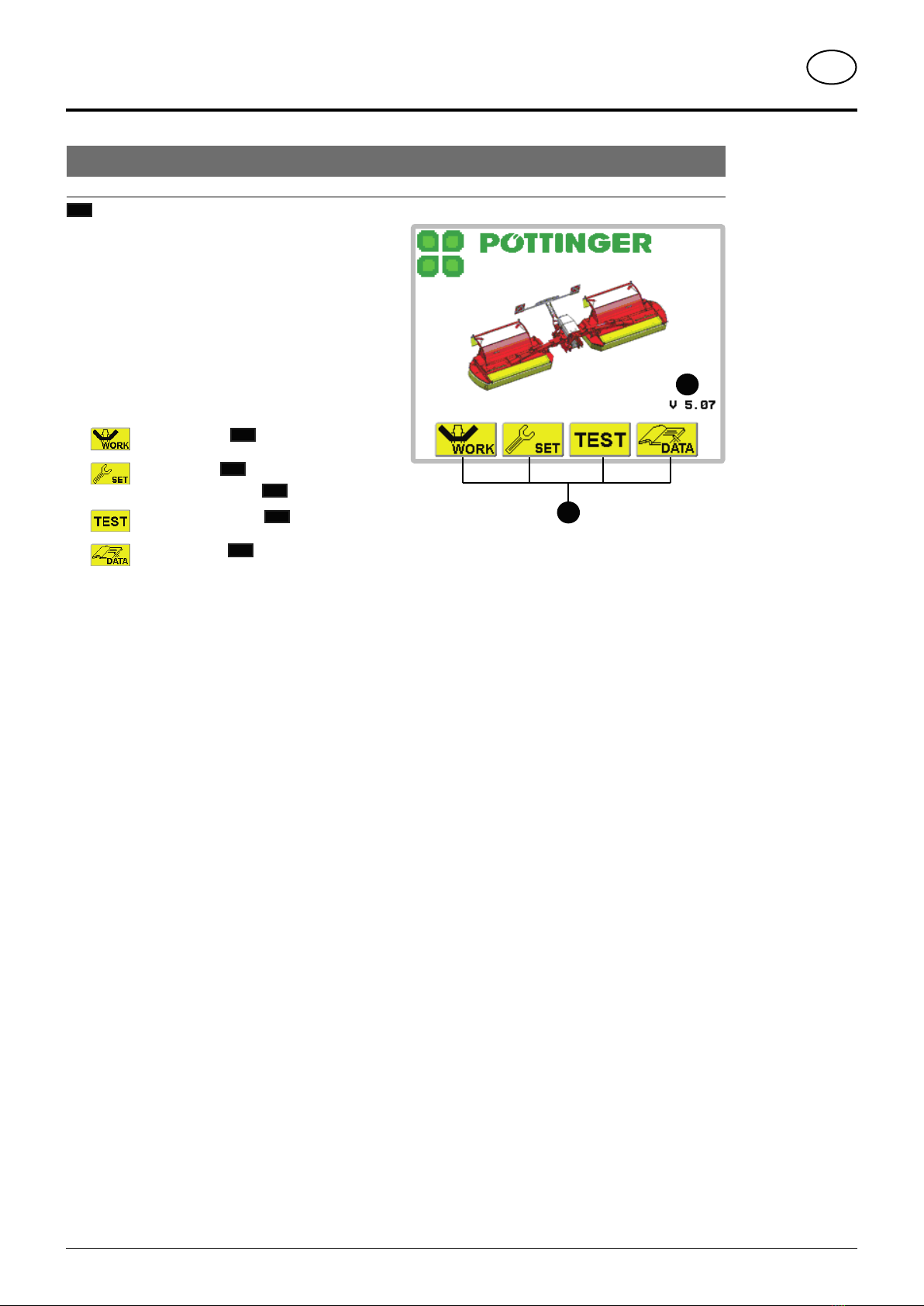
Start menu
M1
After activating the Power Control Terminal
the Start menu appears.
Display:
1…. Software version
2…. Function keys
Function keys:
... Work menu M2
... Set menu M3 / press longer:
Configuration menu M6
... Sensor test menu M4
... Data menu M5
1
2

- 17 -
1400_GB-Power Control_3843
POWER CONTROL GB
Work menu
M2
In Start menu, press function key to open up Work menu.
Press function key to return to Start menu.
13
12
11
12
4
3
1
1
5
6
8
7
2
Note!
To adjust the
relief pressure the
mower units must
be in the neutral
position.
Note!
It is not possible
to change to road
transport position
when, at least,
one cross con-
veyor is not in the
working position.
Display:
1…. Cross conveyor belt speed:
Fast (hare)/Slow(tortoise)(onlywithX8Collector)
2 ... Preselect to either raise or lower cross conveyor.
3 ... Operating condition of mower units:
Working (pic. 1), Field transport (pic. 2),
Road transport (pic. 3)
4 ... a cross conveyor is not in working position
5 ... Tractor speed:
can only be selected if in configuration menu
6 ... ha. per hr.:
only if tractor speed is selected in configuration menu.
7 ... Frontmoweravailable.Ifthissymbolisnotdisplayed,
there is either no front mower available or it
cannot be managed with this control.
8 ... Right rear mower unit relief pressure
9 ... Left rear mower unit relief pressure
10 ... Daily hectare counter only if tractor speed is
selected in configuration menu.
11 ... Slopetravel preselection (only withNovacatV10)
12 ... Side shift (only with Novacat V10)
both arrows point outward = max. width
both arrows point inward = min. width
both arrowspoint in the same direction
= slope travel
13 ... Road transport symbol
Only with the symbol displayed is raising and
lowering out of, or to, the road transport position
possible. If symbol begins to flash then press
[Road transport] key once again.
Function keys:
... Decrease relief pressure of rear
mower units*
... Increasereliefpressureof rearmower
units*
... Activate/deactivate front mower
... Go up one menu level (here: Start
menu)
Hard keys: Raising and lowering
*Momentary pressure differences could arise between left and right rear mower units. But these are
automatically balanced out after the filling process.
9
10

- 18 -
1400_GB-Power Control_3843
POWER CONTROL GB
Lower left mower unit Lowers left mower unit from field transport to working position
Lower front mower Lowers front mower from field transport to working position
Lower right mower unit Lowers right mower unit from field transport to working position
Lower all mower units Lowers all mower units from field transport to working position
Raise left mower unit Raises left mower unit from working position to field transport position.
Raise front mower Raises front mower from working position to field transport position
Raise right mower unit Raises right mower unit from working position to field transport position
Raise all mower units Raises all mower units from working position to field transport position
Road transport
preselection
1. Press preselection key to make raising to and lowering from road
transport position possible.
2. Press either the [Raise] or [Lower] key to move the respective mower
units to, or out of, the road transport position.
Stop Stops any raising or lowering process.
Hard keys: Raising and lowering cross conveyor (only Novacat X8 Collector)
Raise cross conveyor Raises both or the preselected cross conveyor
Lower cross conveyor Lowers both or the preselected cross conveyor
Right cross conveyor
preselection
1. Pressthepreselectionkey tomakeraising or loweringanindividualcross
conveyor possible. The symbol "Right cross conveyor preselection"
2appears on the display.
2. Press the appropriate key, [Raise] or [Lower], to move the relevant
cross conveyor.
Left cross conveyor
preselection
1. Pressthepreselectionkey tomakeraising or loweringanindividualcross
conveyor possible. The symbol "Left cross conveyor preselection"
2appears on the display.
2. Press the appropriate key, [Raise] or [Lower], to move the relevant
cross conveyor.
Note!
Any menu can be
exited by pressing
the ESC key.
Note!
To be able to
activate the key
[Road transport
preselection],
both cross
conveyors must
be in the working
position.
Note!
To be able to
activate the key
[Road transport
preselection],
all mower units
must be in the
field transport
position.
Note!
To change to road
transport position
cardan shaft must
be idle. The [Road
transport] key
will not function
as long as the
cardan shaft is
turning.
Note!
Pressing the "Road
transport prese-
lection" key
will depressurize
the side protec-
tion hydraulic
hoses. (e.g. be-
fore uncoupling)
- 19 -
1400_GB-Power Control_3843
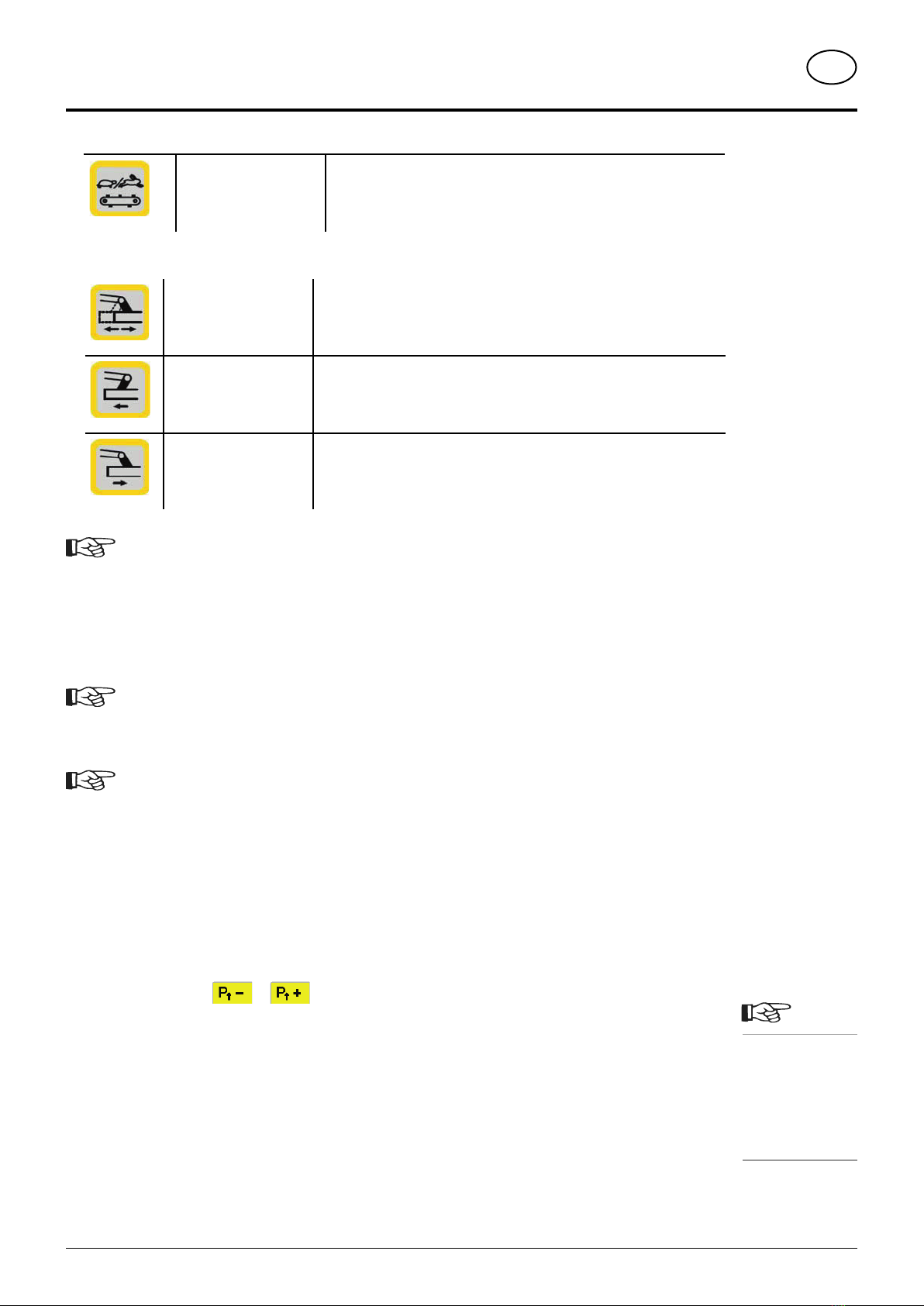
POWER CONTROL GB
Cross conveyor speed
levels
(Optional extra)
Press the key to change the speed level of the cross conveyor belts.
One of two levels can be selected which are represented by a "hare"
or a "tortoise"
Go to the Set menu to adjust the speed of the speed level.
Hard keys: Side shift (only Novacat V10)
Slope travel preselection 1. Press the preselection key to move both rear mower units in the same
direction, one after the other.
2. Press the appropriate key [side shift] to start the side shift in the relevant
direction. The mower units then move one after the other.
Decrease working width /
side shift left
Decreases working width of mower so that both mower units move inward
to end position.
In conjunction with [Slope travel preselection], both rear mower units
move to the left.
Increase working width /
side shift right
Increases working width of mower so that both mower units move outward
to end position.
In conjunction with [Slope travel preselection], both rear mower units
move to the right.
Note!
The keys "Decrease working width" and "Increase working width" are stayput keys (function activated
by briefly pressing the key).
The function is interrupted with the STOP key or by pressing the key for the opposite direction. If
function is interrupted with STOP key, no arrow appears in the display.
Note!
When mowing on slopes it is sensible to position both mower units uphill. Doing so will prevent
streaking.
Note!
Adjusting the working width is only possible in the working and field transport positions.
If both mowers are to be moved to the transport position and one of the mower units is in the field
transport position at max. working width, firstly bring both mower units to min. working width so as
not to exceed the 4 m transport height.
Set relief pressure for hydraulics
Adapt the relief pressure to the ground conditions.
1. Ensure that both mower units are in the neutral position. Otherwise the relief pressure cannot be adjusted.
2. Raise an outside rear unit. If this is even possible, this is equivalent to a relief pressure of approx. 70kg.
3. Press the function keys or to adapt the relief pressure to the ground conditions.
Note!
Raise an outside
rear unit. If this
is even possible,
this is equivalent
to a relief pres-
sure of approx.
70kg.
- 20 -
1400_GB-Power Control_3843
POWER CONTROL GB
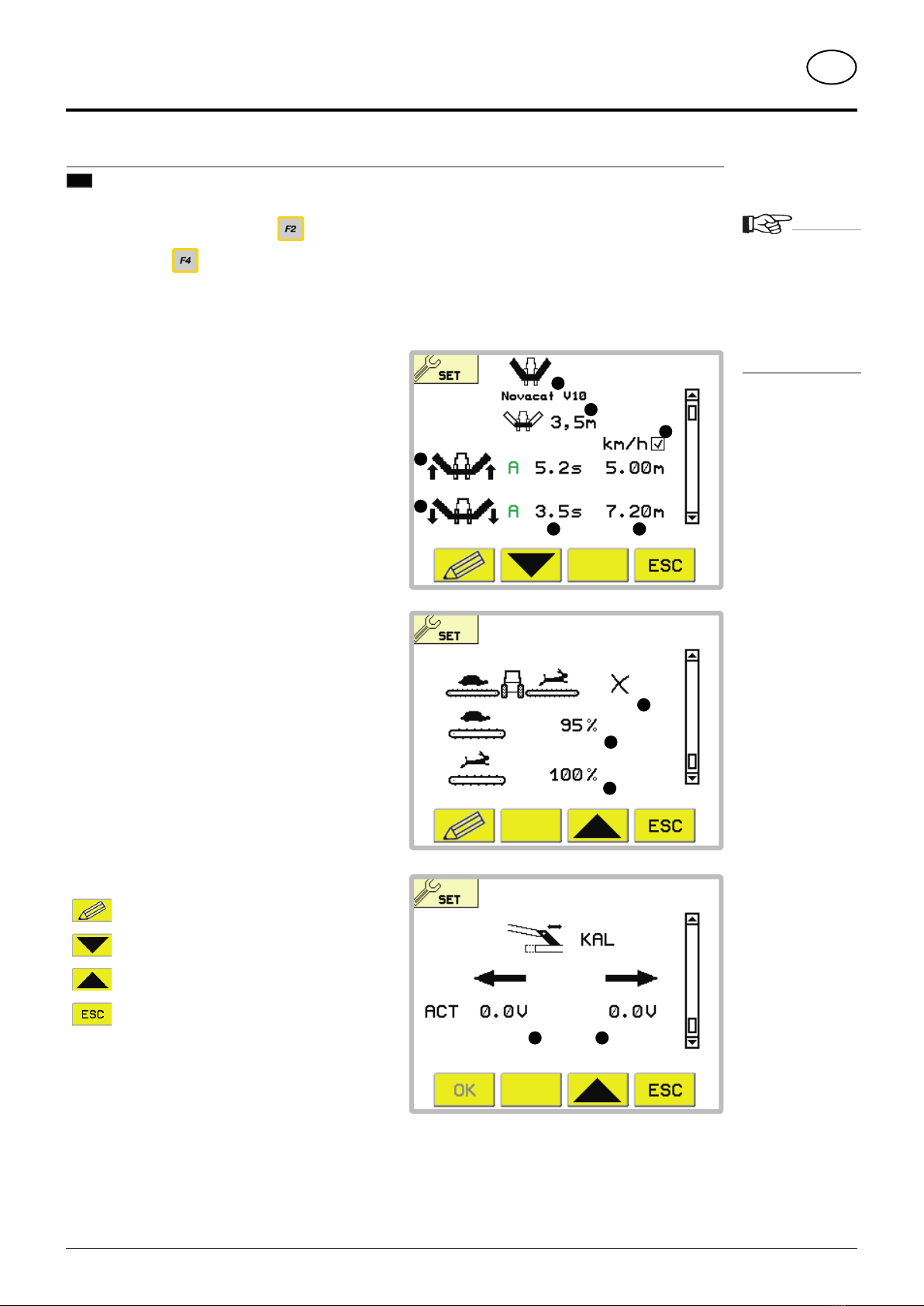
Set menu
M3
In the Start menu, press function key , to open the Set Menu.
Press function key , to return to the Start Menu.
Note:
The values
for the distance
controlled delay
will not appear if
the speed has not
been selected in
the configuration
menu.
1211
1
3
2
5 4
7
6
10
8
9
Display:
1…. Type of machine
2…. Front mower working width (only Novacat V10)
3 ... Time or distance controlled delay when
lowering the rear mower.
4 ... Column for the distance controlled delay
5 ... Column for the time controlled delay
6 ... Line for lowering the mower unit
7 ... Line for raising the mower unit
only Novacat X8 Collector:
8 ... Speed selection for cross conveyor belt:
Tick= Differingspeeds betweenthe left and right
cross conveyor belt (for mowing in contour lines)
Cross = Same speed for both cross conveyor
belts with the possibility of switching between
two speeds.
9 ... Speed regulator for speed 1
(Tortoise): same percentage =
same speed
10 ... Speed regulator for speed 2
(Hare):
only Novacat V10:
11 ... Voltage value for the left angle sensor
12 ... Voltage value for the right angle sensor
Function keys:
... Edit menu entry
... page down
... page up
... change to higher menu (here: Start
Menu)
This manual suits for next models
1
Table of contents
Popular Farm Equipment manuals by other brands

Schaffert
Schaffert Rebounder Mounting instructions

Stocks AG
Stocks AG Fan Jet Pro Plus 65 Original Operating Manual and parts list

Cumberland
Cumberland Integra Feed-Link Installation and operation manual

BROWN
BROWN BDHP-1250 Owner's/operator's manual

Molon
Molon BCS operating instructions

Vaderstad
Vaderstad Rapid Series instructions


