Novalynx 200-WS-02 Series User manual

DOC 200-WS-02 UM 20210413
200-WS-02x
User Manual
WeatherPort
Wind Speed and Direction Sensors
200-WS-02E, 200-WS-02F
Phone (530) 823-7185
Email nova@novalynx.com Website www.novalynx.com

NovaLynx Corporation________________________________________________________________________________
200-WS-02 Page 2 April 2021
Receiving and Unpacking
Carefully unpack all components and compare to the packing list. Notify NovaLynx Corporation
immediately concerning any discrepancy. Inspect equipment to detect any damage that may have
occurred during shipment. In the event of damage, any claim for loss must be filed immediately with
the carrier by the consignee. Damages to equipment sent via Parcel Post or UPS require the consignee
to contact NovaLynx Corporation for instructions.
Returns
If equipment is to be returned to the factory for any reason, call NovaLynx between 8:00 a.m. and 4:00
p.m. Pacific Time to request a Return Authorization Number (RA#). Include with the returned
equipment a description of the problem and the name, address, and daytime phone number of the
sender. Carefully pack the equipment to prevent damage or additional damage during the return
shipment. Call NovaLynx for packing instructions in the case of delicate or sensitive items. If packing
facilities are not available take the equipment to the nearest Post Office, UPS, or other freight service
and obtain assistance with the packaging. Please write the RA# on the outside of the box.
Warranty
NovaLynx Corporation warrants that its products are free from defects in material and workmanship
under normal use and service for a period of one year from the date of shipment from the factory.
NovaLynx Corporation's obligations under this warranty are limited to, at NovaLynx's option: (i)
replacing; or (ii) repairing; any product determined to be defective. In no case shall NovaLynx
Corporation's liability exceed product's original purchase price. This warranty does not apply to any
equipment that has been repaired or altered, except by NovaLynx Corporation, or that has been
subjected to misuse, negligence, or accident. It is expressly agreed that this warranty will be in lieu of
all warranties of fitness and in lieu of the warranty of merchantability.
Address
NovaLynx Corporation
431 Crown Point Circle, Suite 120
Grass Valley, CA 95945-9531 USA
Phone: (530) 823-7185
Email: nova@novalynx.com
Website: www.novalynx.com
Copyright © 1988-2021 by NovaLynx Corporation

NovaLynx Corporation________________________________________________________________________________
200-WS-02 Page 3 April 2021
CONTENTS
1 FORWARD ....................................................................................................................................................................... 4
2 INTRODUCTION ............................................................................................................................................................... 4
3 PRECAUTIONS ................................................................................................................................................................. 5
4 SPECIFICATIONS .............................................................................................................................................................. 5
5 SITE SELECTION ............................................................................................................................................................... 6
6 TAIL ASSEMBLY ................................................................................................................................................................ 6
7 MOUNTING OPTIONS ...................................................................................................................................................... 7
8 INSTALLATION ................................................................................................................................................................. 8
9 WIRING DIAGRAMS ......................................................................................................................................................... 9
10 MAINTENANCE .......................................................................................................................................................... 10
10.1 General Inspection ................................................................................................................................................ 10
10.2 Lubrication and Adjustment ................................................................................................................................. 10
11 FUNCTIONAL TESTS ................................................................................................................................................... 11
11.1 Anemometer Electrical Test .................................................................................................................................. 11
11.2 Potentiometer Electrical Test ............................................................................................................................... 12
12 SENSOR REPAIR ......................................................................................................................................................... 12
APPENDIX A Tripod Dimensions ............................................................................................................................................ 13

NovaLynx Corporation________________________________________________________________________________
200-WS-02 Page 4 April 2021
1 FORWARD
Thank you for purchasing NovaLynx products. NovaLynx has been designing and manufacturing
weather instruments since 1988. NovaLynx represents several well-known brands of quality
manufacturers, including Gill Instruments, RM Young, Kipp & Zonen, and Vaisala. It is our hope that our
products will meet all your monitoring requirements.
2 INTRODUCTION
WeatherPort 200-WS-02 Wind Sensors are moderately priced anemometers designed for general
applications up to 125 mph (56 m/s). The sensors are easy to install and maintain. They are
constructed of injection molded thermoplastic, anodized aluminum, and stainless steel for reliable
operation in adverse environments.
The base of the sensor is designed to mount on a vertical 1.07" (27 mm) diameter mast. If the sensor
cannot be mounted at the top of the mast, an optional side-mount boom (NovaLynx 200-153) is
available. Each sensor includes 40-feet (12 m) of cable.
The 200-WS-02 consists of two major parts: a rotating cup style anemometer for measuring wind
speed and a wind vane for measuring horizontal wind direction.
Wind Speed Measurement
Air movement (wind) causes the cup and hub assembly to rotate, moving the permanent magnets
embedded in the hub over a magnetic reed switch fixed in the base. Three closures of the reed
switch will be produced for each revolution of the cup assembly. The ratio of closed-to-open time is
nominally 1/10 of the total period for a revolution of the wind cups. This duty cycle may change
slightly as the sensor ages and with exposure to temperature extremes.
Wind Direction Measurement
The wind vane is mounted directly above the wind speed sensor. Fluctuations in the wind direction
are measured by the sensor as the aerodynamics of the counterweight and the tail try to keep
aligned to the path of the wind. The wind vane is coupled to a 20K ohm single turn potentiometer.
When connected to a well-regulated voltage source the output voltage of the sensor is
proportional to the wind direction and can be read by a single-ended analog input channel.
The potentiometer has a “dead band” of approximately 5 degrees between the ends of the
resistive media in the potentiometer. This gap is aligned to the NORTH label on the body of the
sensor.

NovaLynx Corporation________________________________________________________________________________
200-WS-02 Page 5 April 2021
3 PRECAUTIONS
Handle the sensor carefully to avoid undue stress on the potentiometer which supports the wind vane
assembly. Do not lay the sensor on its side which would place strain on the cup assembly.
The shield wire in the sensor cable is electrically connected to the shaft holding the vane assembly. The
purpose is to bleed off static that would otherwise affect the sensor output. Therefore it is important
to earth ground the shield wire for best results.
Installations where nearby lightning strikes are likely should include a properly grounded lightning rod
above the level of the sensor, preferably on a separate tower.
4 SPECIFICATIONS
Measurement Range 125 mph max (56 m/s max)
Speed Threshold 1.2 mph (0.54 m/s)
Speed Constant 1.25 mph = 1 Hz (0.5588 m/s = 1 Hz)
Accuracy 1 mph (0.4470 m/s) or ±3%
Transducer Type Reed switch, magnet activated
Maximum Rating 10 mA @ 50 V (ac or dc)
Turning Radius 4 inch (10.16 cm)
Measurement Range 0-360 degree azimuth
Potentiometer Gap 5 degree (approximate)
Accuracy ±3 degrees
Vane Threshold 1.2 mph (0.5364 m/s)
Distance Constant 1.5 feet (45.72 cm)
Time Constant 2 seconds
Damping Ratio 0.4
Transducer Type 20k ohm, 20% tolerance, 1% linearity, bushing type bearing
Maximum Rating 1/4 watt
Turning Radius 10.5 inch (26.67 cm)
Cable, 200-WS-02E 40 feet (12 m), 4 conductor, 24 AWG, shielded, tinned leads
Cable, 200-WS-02F 40 feet (12 m), 5 conductor, 24 AWG, shielded, tinned leads
Mounting 1.07 inch diameter by 0.82 inch socket (27 mm dia x 21 mm)
Assembled Dimensions 12.0" H x 15.2" W x 8.2" D (31 x 39 x 21 cm)
Shipping Dimensions 10.5 x 6.75 x 6.25 inches (27 x 17 x 16 cm)
Weight / Shipping 1.95 lbs (0.88 kg) / 3 lbs (1.4 kg)
Anemometer Specification
Wind Vane Specification
Overall Specification

NovaLynx Corporation________________________________________________________________________________
200-WS-02 Page 6 April 2021
5 SITE SELECTION
WARNING: Avoid overhead power lines whenever possible. If there are overhead power lines, use
extreme care to prevent contact with the power lines while installing the equipment.
Choose a mounting location for the wind sensor that is free of obstructions since nearby objects can
create eddy currents that will affect the wind measurements. Try to locate the wind sensor so that the
nearest object is 10 x T away from the wind sensor mast, where T is the height of the object.
Roof mounted sensors should be placed on the upwind side of the building and away from all exhaust
vents. If the sensor is located on top of a building the sensor height should be 1.5 x H, where H is the
height of the building.
In all cases when the wind sensor data is to be correlated to National Weather Service data or World
Meteorological Organization data, the standard exposure is 33 feet (10 meters) above the ground.
6 TAIL ASSEMBLY
The tail piece must be assembled to the vane shaft before installing the sensor.* Locate the tail piece
(packed with this manual). Remove the blue tape from the shaft and save the two screws stored there.
Slide the tail piece into the slot in the shaft and align the screw holes. Secure the tail with two screws
using a #1 Phillips screwdriver.
4-40 x 1/4 PAN PH SS
TAIL ASSEMBLY
Counterweight Hub Shaft
Tail
Vane setscrew
Potentiometer setscrew
(on opposite side)
DWG 890-0015-02
Figure 1
*Pre-assembled in some cases.
NovaLynx Corporation________________________________________________________________________________
200-WS-02 Page 7 April 2021
7 MOUNTING OPTIONS
CAUTION: Be careful when working on equipment that is mounted above you. Do not allow others to
stand below when equipment is being installed as falling objects can be hazardous.
The support for the sensor must be rigid or supplemented with guy wires. A mast can be assembled
from pipe, using larger pipe at the base and ending in ¾" IPS pipe at the top. The mast should be easy
to reach for servicing the sensor and should be properly anchored and grounded. A tilt-down
arrangement can eliminate the need for lifts or ladders during installation and service.
NovaLynx tripods are a convenient alternative for temporary and permanent installations. The tripods
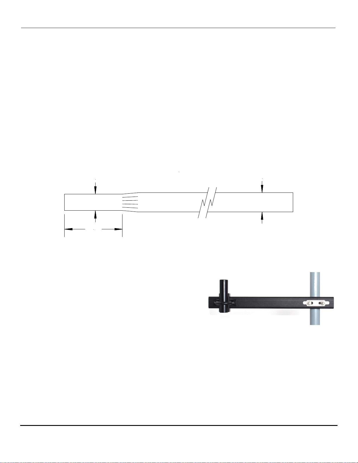
are available in three sizes: 3', 5' and 10' tall (Appendix A). Masts are available in various lengths.
Swaged mast segments can be fitted together to obtain the overall height needed. The swaged end is
the correct diameter for mounting 200-WS-02 sensors.
1.07" 1.25"
SWAGED ALUMINUM MAST
3.75"
Note: The base of the 200-WS-02 sensor accepts 1.07" (27 mm) diameter pipe.
If the wind speed sensor cannot be mounted at the top
of the mast, the NovaLynx 200-153 Mounting Arm (sold
separately) can be mounted to the mast or tower leg at
the desired height.
200-153 Mounting Arm
The supporting mast or tripod should be properly grounded. In areas where lightning is likely, install a
lightning rod to minimize lightning damage. NovaLynx 190-Series Lightning and Surge Protection
products are available to accommodate most applications.

NovaLynx Corporation________________________________________________________________________________
200-WS-02 Page 8 April 2021
8 INSTALLATION
NOTE: Wind direction sensors are usually aligned to true north, rather than magnetic north. True north
is usually found by reading a magnetic compass and applying the correction for magnetic declination.
On-line calculators are available to enter your location and obtain the correction factor. One such
website is: https://www.ngdc.noaa.gov/geomag-web/#declination
1. Loosen the two mounting screws on the base of the sensor.
2. Place the sensor on the top of the mast or mounting stub.
3. Align the NORTH label to geographic (true) north.
4. Tighten the mounting screws using moderate torque.
The PVC jacket of the cable will last for many years outdoors under normal circumstances. In harsh
environments it may be necessary to protect the cable with conduit.
Route the sensor cable down the mast and to the monitoring equipment in the most direct manner.
Fasten the cable to the mast with cable ties to prevent whipping during high velocity winds. For best
results, use plastic cable ties that are resistant to ultra-violet radiation and place them at two foot
intervals. Leave a "drip loop" of cable below the entry point to the equipment enclosure to help keep
moisture out.
Birds of all sizes find the shaft of the wind vane a desirable place to land. The weight of a large bird can
easily damage the potentiometer by breaking it loose from the body of the sensor. The best way to
reduce this hazard is to provide an alternate landing site nearby that would be more attractive to the
weary bird.
NovaLynx Corporation________________________________________________________________________________
200-WS-02 Page 9 April 2021
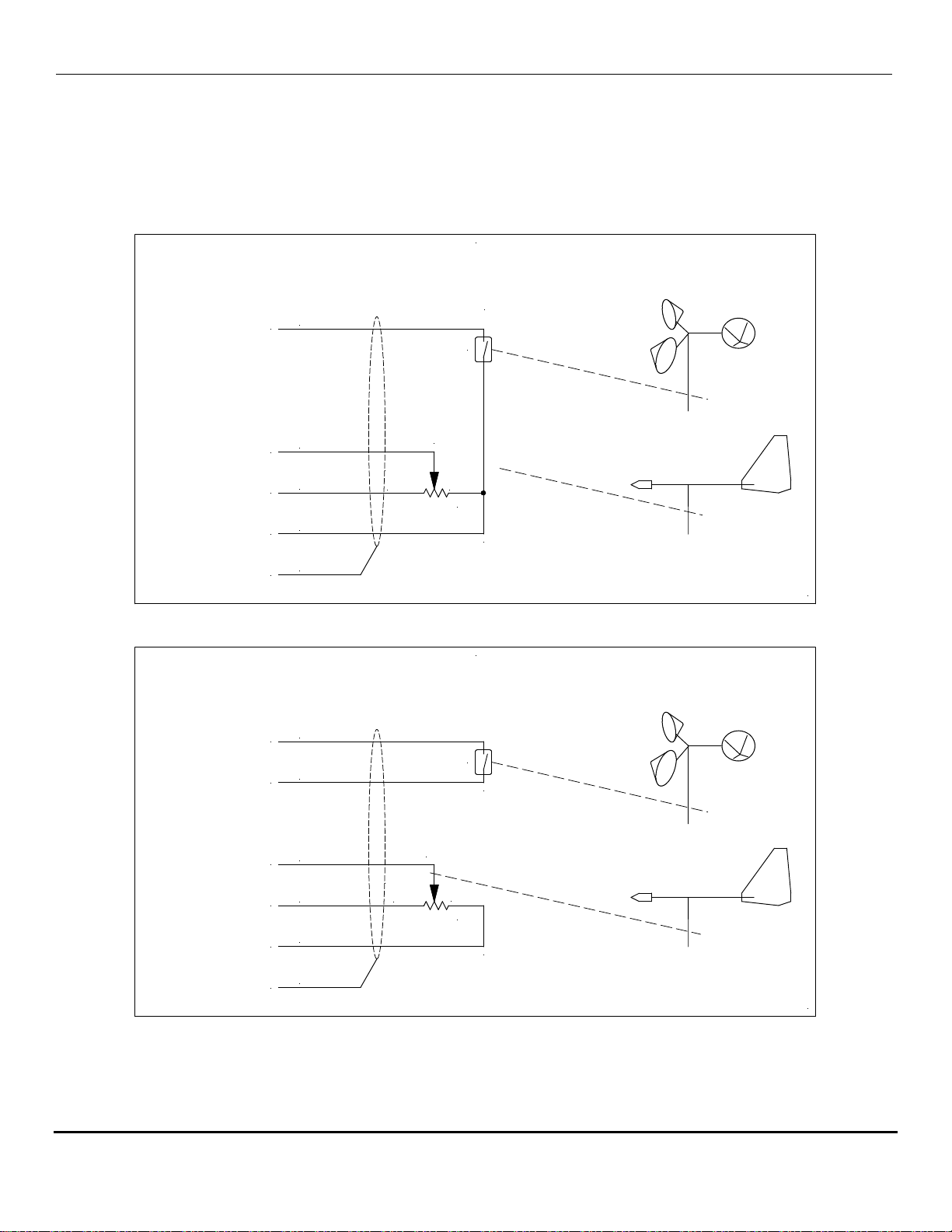
9 WIRING DIAGRAMS
CAUTION: Turn off power to the logger or other monitoring device before connecting the sensor.
CCW CW
S
355° ELECTRICAL ANGLE
3 PER REV
Earth Ground Clear
Black
Red
Green
White
Reed Switch
20k ohms
Signal Ground
Vref
Direction Signal
Speed Signal
DWG 890-0023-04
200-WS-02E
Wind Speed and Direction Sensor
200-WS-02F
Wind Speed and Direction Sensor
Speed Signal
Speed Ground
Direction Signal
Vref
Direction Ground
20k ohms
Reed Switch
White
Brown
Green
Red
Black
Clear
Earth Ground
3 PER REV
355° ELECTRICAL ANGLE
S
CW CCW
DWG 890-0016-04
NovaLynx Corporation________________________________________________________________________________
200-WS-02 Page 10 April 2021
10 MAINTENANCE
Wind sensors experience vibration due to high velocity wind. The vibration can loosen the mounting
screws or the support structure. Regular inspection of the mounting hardware is required to prevent
damage to the sensor.
10.1 General Inspection
CAUTION: On occasion a sensor may be damaged by high wind or by a large bird landing on the wind
vane. Before approaching the weather station, check whether the wind vane is in position on the top
of the sensor. If it appears to be out of position, exercise extreme caution when working near the
station because the vane could detach and fall.
1. Tighten the mounting screws at the base of the sensor if necessary (do not over-tighten).
2. Spin the anemometer cup assembly. It should turn freely.
3. Rotate the wind vane gently. It should turn freely with no "rough" spots.
4. Inspect the counterweight to ensure it is firmly cemented to the vane. Repair if necessary.
5. Inspect the wind vane to ensure the tail is vertical and the screws holding it to the vane are snug.
6. Inspect the cable and secure it to the mast to prevent damage due to wind whipping.
10.2 Lubrication and Adjustment
The bearings in the 200-WS-02 sensor may eventually require lubrication to restore free movement of
the anemometer cup assembly or the wind vane. Some disassembly is required to access the bearings,
so it is best to dismount the sensor before servicing. Use a light machine oil (such as fishing reel oil) for
lubrication. Do not use WD-40 or similar products, as they wear off quickly, leaving the bearing dry and
susceptible to rust.
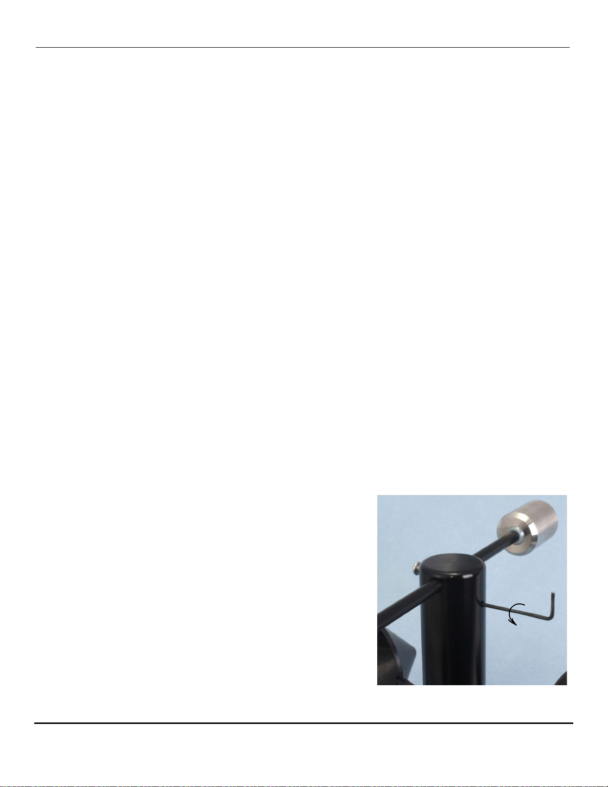
Disassembly
1. Remove the sensor from the weather station and take it to a
clean workbench.
2. Loosen the set screw that holds the vane to the
potentiometer shaft. The set screw requires a 1/16" Allen
wrench.
3. Lift the tail assembly straight up carefully. The shaft of the
potentiometer will be exposed, and the top of the bearing in
the cup assembly will be visible.
4. Wipe off any dust that has accumulated.

NovaLynx Corporation________________________________________________________________________________
200-WS-02 Page 11 April 2021
Lubrication
1. Apply a tiny drop of light machine oil (e.g. fishing reel oil) to
the shaft of the potentiometer where it enters the bearing.
Turn the potentiometer shaft to work the oil into the bearing.
Do not apply too much oil as it could spread inside the
potentiometer and contaminate the resistance material.
2. Apply a few drops of light machine oil to the top of the ball
bearing that supports the cup assembly. Spin the cup
assembly to work the oil into the bearing.
3. Wipe excess oil off of the bearing and potentiometer shaft.
Test and Balance
1. Perform the Anemometer Electrical Test (Section 11.1). The test will confirm that the reed switch
responds to the magnets when the cup assembly rotates.
2. Perform the Potentiometer Electrical Test (Section 11.2). This test will ensure the electrical output
of the direction sensor is working. The procedure includes information on how to align the vane
with the potentiometer. Install the vane according to the instructions.
3. The final step is to balance the wind vane. Hold the base of the sensor and turn it sideways so that
the sensor is horizontal to the ground. If the vane is balanced it should show no tendency to rotate.
If it is not balanced either the counterweight or tail will rotate downwards. If the vane is out of
balance, loosen the vane set screw (Figure 1) and slide the vane either forwards or backwards to
balance the vane. Don’t forget to align the tail with the vertical axis while you tighten the set screw.
11 FUNCTIONAL TESTS
The following checks can be done with an ohm-meter after the sensor has been removed from the
tower or tripod. These tests can help determine whether the sensor needs repair or adjustment.
11.1 Anemometer Electrical Test
Set the ohm-meter to a low resistance range and touch its leads together to check for zero ohms. If it is
an analog meter adjust the dial to read zero ohms. Connect the meter to the wind speed output signal
wire and ground wire.
Rotate the cup assembly slowly until you notice the meter reading drop to less than 10 ohms. Continue
to rotate until the switch opens (high resistance). Do this for each of the 3 magnets in the cup
assembly. If the meter always reads a low resistance then the reed switch is not opening (the contacts
may have welded together) or there may be a short circuit in the cable. If the switch never closes then

NovaLynx Corporation________________________________________________________________________________
200-WS-02 Page 12 April 2021
there may be a break in the cable or the magnets are not near enough to activate the switch. Check
the distance between the cup assembly and the base. The gap should be about 1/16" (1.6 mm).
11.2 Potentiometer Electrical Test
Wind vane calibration involves checking the potentiometer output and verification of the sensor
alignment to north.
Set the ohm-meter to the 20k range (or greater range if needed). Connect the black meter lead to the
black sensor wire, and the red meter lead to the red sensor wire. The reading on the meter should be a
stable output of about 20,000 ohms (+/-20%). Rotate the vane once around while watching the meter
to ensure the reading does not change.
Connect the red meter lead to the green wire. Observe that the meter reading changes as you rotate
the vane. Check the "dead band" where the meter goes to "infinite" and verify that the counterweight
is pointing the same direction as the NORTH label on the base of the sensor. Now rotate the vane
slowly clockwise and observe that the resistance changes smoothly from near zero to the maximum
just before hitting the "dead band" again as you approach north.
If the "dead band" does not align with the NORTH label then the position of the vane can be changed
to correct the alignment:
1. Using a 1/16" Allen wrench, loosen the potentiometer set screw located on one side of the hub.
2. Lift upwards to remove the vane assembly from the sensor. Note that the potentiometer body is
bonded to the sensor body and should not move.
3. Using an ohmmeter to monitor the potentiometer output, turn the potentiometer shaft until the
center of the gap is located. You may wish to make a mark on the shaft aligned to the NORTH label.
4. Aim the counterweight in the same direction as the NORTH label and carefully lower the hub onto
the potentiometer shaft. Tighten the set screw. Note: There must be a small gap between the hub
and the cup assembly below, to allow the cups to turn freely.
5. Check your work by observing the meter as you swing the vane across north.
12 SENSOR REPAIR
The working elements of the sensor (potentiometer, anemometer cup assembly and shaft) can be
replaced as a unit. Order NovaLynx 200-WS-02E-ASSY or 200-WS-02F-ASSY depending on the type of
sensor you wish to repair. The kit includes 40 feet of cable. Save the wind vane and base from your
current sensor to complete the repair.

NovaLynx Corporation
200-WS-02 Page 13 April 2021
APPENDIX A TRIPOD DIMENSIONS
Other manuals for 200-WS-02 Series
1
This manual suits for next models
2
Table of contents
Other Novalynx Accessories manuals

Novalynx
Novalynx 200-WS-01B User manual

Novalynx
Novalynx 230-600C User manual

Novalynx
Novalynx 225-HMP60A User manual

Novalynx
Novalynx 200-WS-22 User manual

Novalynx
Novalynx 200-WS-01B User manual

Novalynx
Novalynx 200-WS-02 Series User manual

Novalynx
Novalynx 200-WS-23 User manual

Novalynx
Novalynx 200-WS-04 User manual

Novalynx
Novalynx 200-WS-02E User manual

Novalynx
Novalynx 260-2520 User manual


