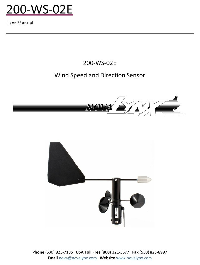
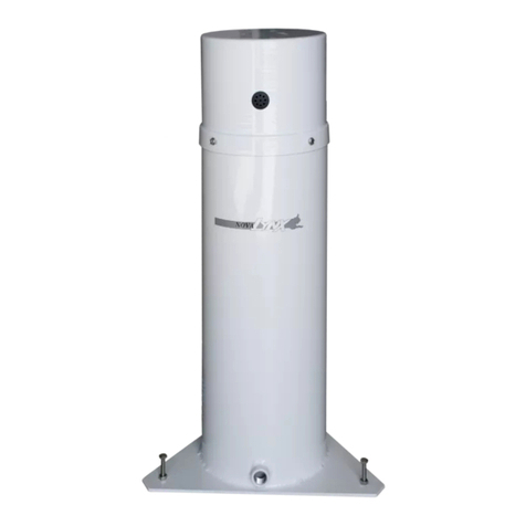
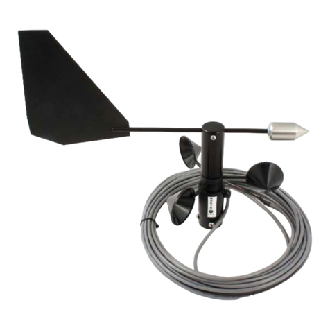
Novalynx 200-WS-22 User manual

NOVALYNX CORPORATION
MODEL 200-WS-22 & 200-WS-22A
CURRENT LOOP WIND SENSOR
INSTRUCTION MANUAL
REVISION DATE: 05/20/2004

i
Receiving and Un acking
Carefully unpack all componen s and compare o he packing lis . No ify NovaLynx
Corpora ion immedia ely concerning any discrepancy. Inspec equipmen o de ec any
damage ha may have occurred during shipmen . In he even of damage, any claim for
loss mus be filed immedia ely wi h he carrier by he consignee. Damages o
equipmen sen via Parcel Pos or UPS require he consignee o con ac NovaLynx
Corpora ion for ins ruc ions.
Returns
If equipmen is o be re urned o he fac ory for any reason, call NovaLynx be ween
8:00 a.m. and 4:00 p.m. Pacific Time o reques a Re urn Au horiza ion Number (RA#).
Include wi h he re urned equipmen a descrip ion of he problem and he name,
address, and day ime phone number of he sender. Carefully pack he equipmen o
preven damage or addi ional damage during he re urn shipmen . Call NovaLynx for
packing ins ruc ions in he case of delica e or sensi ive i ems. If packing facili ies are no
available ake he equipmen o he neares Pos Office, UPS, or o her freigh service
and ob ain assis ance wi h he packaging. Please wri e he RA# on he ou side of he
box.
Warranty
NovaLynx Corpora ion warran s ha i s produc s are free from defec s in ma erial and
workmanship under normal use and service for a period of one year from he da e of
shipmen from he fac ory. NovaLynx Corpora ion's obliga ions under his warran y are
limi ed o, a NovaLynx's op ion: (i) replacing; or (ii) repairing; any produc de ermined o
be defec ive. In no case shall NovaLynx Corpora ion's liabili y exceed produc 's original
purchase price. This warran y does no apply o any equipmen ha has been repaired
or al ered, excep by NovaLynx Corpora ion, or ha has been subjec ed o misuse,
negligence, or acciden . I is expressly agreed ha his warran y will be in lieu of all
warran ies of fi ness and in lieu of he warran y of merchan abili y.
Address
NovaLynx Cor oration
4055 Grass Valley Highway, Suite 102
Auburn, CA 95602
Phone: (530) 823-7185
Fax: (530) 823-8997
Email: nova@novalynx.com
Website: www.novalynx.com
Copyrigh © 1988-2006 by NovaLynx Corpora ion

ii
TABLE OF CONTENTS
Section No. Page No.
1.0 INTRODUCTION .................................................. 1
1.2 Physical Descripion........................................... 1
1.2.1 The Wind Sensor ...................................... 1
1.2.2 The Encoder.......................................... 1
2.0 SPECIFICATIONS ................................................. 2
3.0 THEORY OF OPERATION........................................... 2
3.1 Wind Speed Measuremen ..................................... 2
3.2 Wind Direc ion Measuremen . . . . . . . . . . . . . . . . . . . . . . . . . . . . . . . . . . . 3
4.0 INSTALLATION ................................................... 3
4.1 Unpacking .................................................. 3
4.2 Wind Sensor Insallaion ....................................... 4
4.3 Transmi er Insallaion......................................... 4
5.0 OPERATIONAL TESTING ........................................... 5
5.1 Circui Board Adjusmens ...................................... 6
6.0 MAINTENANCE ................................................... 6

iii

1
NovaLynx Cor oration
Model 200-WS-22 & 200-WS-22A Current Loo Wind Sensor
Instruction Manual
1.0 INTRODUCTION
The NovaLynx Model 200-WS-22 Curren Loop Wind S a ion measures wind speed
and direc ion and conver s each measuremen in o a 4-20 mA ou pu signal for use by
process con rols or moni oring sys ems. Ex ernal power is no required since he
encoding elec ronics for wind speed and for wind direc ion are isola ed and powered
from heir respec ive 2-wire curren loops. NovaLynx offers wo versions of he Wind
S a ion; he 200-WS-22 measures bo h wind speed and direc ion, while he 200-WS-
22A measures only wind speed. Bo h models con ain wo subassemblies: he wind
sensor and he signal condi ioning elec ronics assembly.
The wind sensor used in bo h versions of he Wind S a ion includes a hree cup
anemome er and a wind vane. The sensor is ruggedly cons ruc ed using UV resis an
ABS plas ic and anodized aluminum par s. The cable connec ing he pole-moun ed
wind sensor o he encoder elec ronics package is ypically 40 fee in leng h bu may be
ex ended for a o al leng h of 250 fee . The encoded curren loop signals are capable of
being ransmi ed over dis ances of up o several miles. The elec ronics package,
ypically moun ed indoors, is supplied ins alled inside a gaske ed NEMA-4X enclosure.
The measuremen ime base for he wind speed- o-curren conversion in he encoder is
crys al con rolled for s able, long- erm accuracy. Ra iome ric signal condi ioning is used
in he direc ion measuremen circui ry o minimize drif and non-lineari y.
1.2 Physical Descri tion
1.2.1 The Wind Sensor
The wind sensor is he ro a ing assembly wi h he hree cup anemome er and wind
vane for measuring wind speed and wind direc ion. The wind vane is moun ed on o a
common axis wi h he anemome er and includes a ail fin wi h a nose weigh ha
provides balance. The wind vane is coupled o an angular encoder ha is housed wi hin
he sensor's cylindrical wea her skir .
1.2.2 The Encoder
The encoder elec ronics package is housed wi hin a sealed, NEMA enclosure. The
circui ry con ains wo independen 4-20 mA da a channels, one for wind speed and he
one for wind direc ion. Each channel receives i s power from i s respec ive 2-wire
measuremen loop.

2
2.0 SPECIFICATIONS
SENSOR
Wind S eed
Measuremen range 0-100 mph, (0-50 m/s for WS-22M)
Speed cons an 1.25 mph = 1 pps
75 mph = 60 Hz (pps)
Transducer ype Reed swi ch
Speed hreshold 1.2 mph
Accuracy 1 mph or ± 3%
Wind Direction
Range 0-360 Deg Az
Transducer ype Po en iome er, 20 k ohms, conduc ive plas ic
Po en iome er gap 5°
Azimu h accuracy ± 3°
Threshold 1.2 mph
Bearings Bushing
TRANSMITTER UNIT
Curren loop ou pu span 4 o 20 mA, Propor ioned o 0-100 mph & 0-360°
(Propor ioned o 0-50 m/s & 0-360° for WS-22M)
Supply vol age range 10 o 48 Vdc
2-wire loop in erface Screw erminal block
In erface power Derived from curren loop
Dimensions
GENERAL
Moun ing 1" o.d. pipe
Cable 5 Conduc or, 24 AWG, Shielded, 40' s andard
Dimensions
200-WS-22 (WS/WD) 12" H x 10" W
200-WS-22A (WS) 4.5" H x 8.5" W
Elec ronics enclosure 4.7" H x 7.8" W x 3.5" D
Sys em weigh /shipping 5 lbs/7lbs
3.0 THEORY OF OPERATION
3.1 Wind S eed Measurement
The Model 200-WS-22 wind sensor has been designed o provide measuremen of
wind speed and wind direc ion. Wind speed is measured by a ro a ing assembly of
hree cups. The hree cups are a ached on o a cen ral shaf ha suppor s he cups as
well as provides a moun ing poin for he sensor's ball bearing. The ball bearing
provides smoo h ro a ion of he cups and helps produce an accura e measuremen .

3
The anemome er's precision ball bearing is pro ec ed from he wea her and has life ime
lubrica ion. The ro a ion of he cups is sensed by a magne ically ac iva ed swi ch. The
swi ch is in a fixed posi ion while hree magne s are fas ened o he ro a ing cup
housing. The number of swi ch closures per ro a ion is conver ed in o a frequency ha
is propor ional o he wind speed in miles per hour. The full-scale (20 mA) ou pu of he
wind speed channel represen s a measuremen of 100 mph.
3.2 Wind Direction Measurement
Wind direc ion is measured by a ro a ing device as well. The wind vane ro a es abou i s
cen ral shaf in response o changes in he wind's direc ion. The coun erweigh a he
end of he wind vane nose balances he weigh of he moving mass over i s suppor ing
bearing. I is impor an ha he wind sensor be ins alled in a loca ion free from any
obs ruc ions ha would dis or he na ural flow of air across he sensor. The vane's
ro a ion is ransmi ed o a s a ionary po en iome er loca ed inside he sensor housing.
As he shaf ro a es, he resis ance of he po en iome er a i s wiper changes. The
sensor has been designed o produce an increasing resis ance as he wind direc ion
increases from zero o 360 Degrees Azimu h. From above he sensor his increase in
direc ion will appear as a clockwise ro a ion of he vane. The opposi e is rue for a
decreasing wind direc ion. A wind changing from 360 owards zero degrees resul s in a
decrease in resis ance and a coun erclockwise ro a ion.
Applica ion of a vol age across he po en iome er allows measuremen of he wind
direc ion as a changing vol age. The vol age changes are conver ed by he encoder
circui ry in o a propor ional 4 o 20 milliampere signal wi h 4 mA equal o zero degrees
and 20 mA equal o 360 degrees. The full-scale span of he direc ion channel means
ha he vane nose is poin ing oward 360 degrees or Nor h.
The po en iome er used as a direc ion sensor for wind direc ion has an arc of resis ance
discon inui y or "deadband" ( ypically 5-10°). The deadband is loca ed be ween he 360
degree and he 0 degree poin s (Nor h is indica ed by he se screw in he moun ing
base). Typically, he deadband is cen ered on he Nor h poin . This means ha he
sensor really does no measure zero degrees bu ins ead s ar s measuring a 2 o 5
degrees. Similarly, he end of he direc ion measuremen occurs a 355 o 357 degrees
and no exac ly a 360. When he wind vane is poin ing in his region he loop curren
will be encoded as an under-scaled value of approxima ely 3.6 mA.
4.0 INSTALLATION
4.1 Un acking
Emp y he loose packing ma erial from he corruga ed shipping con ainer and carefully
lif ou he wind sensor assembly. Refer o he warran y page a he fron of he manual
for informa ion regarding re urning damaged or incorrec equipmen .

4
The following i ems should be included in he shipping con ainer for Model 200-WS-22:
1. Wind Speed & Wind Direc ion sensor, wi h 40 fee of cable
2. Transmi er Housing Assembly
3. Ins ruc ion Manual
4.2 Wind Sensor Installation
Choose he moun ing loca ion for he wind sensor ha is free from obs ruc ions. Use
ex reme care o preven con ac wi h elec rical power lines while erec ing he uni . A
ypical ins alla ion will posi ion he wind sensor approxima ely 33 fee (10 me ers) above
he highes obs acle wi hin a 990 foo (300 me er) radius of he moun ing loca ion.
Posi ion he Model 200-WS-22 sensor on o he end of a 1" o.d. TV mas ubing or a
3/4" Schedule 40 pipe. If he pole is me al i should be elec rically grounded o minimize
he probabili y of any ligh ning damage. Ro a e he anemome er on he pole so ha he
wo se screws on he anemome er base are facing Nor h. Magne ic Nor h is adequa e
for mos ins alla ions. Should a True Nor h alignmen be required, he magne ic
declina ion a he sensor loca ion mus known and applied o he compass reading.
Tigh en he bo om se screw o fix he direc ional orien a ion.
4.3 Transmitter Installation
Moun he ransmi er enclosure in a loca ion where i can be convenien ly connec ed o
he wind sensor.
Rou e he sensor signal cable in he mos direc manner possible. Avoid sharp corners
and edges. Do no crease or fold he cable. The cable mus be pro ec ed from high
winds. Use an appropria e fas ener (plas ic cable ies, s aples, e c.) o secure he cable
o i s suppor s ruc ure. Use care o avoid punc uring he cable jacke if s aples are used
o a ach he cable o a wooden suppor .
The s andard wind sensor is supplied wi h 40 fee of cable. In he even ha he
in erconnec ing cable needs o be ex ended, use good splicing echniques and
wa erproof he splice if i will be exposed o he wea her. The 5-conduc or cable o he
wind sensor may be ex ended o up o 250 fee in leng h wi hou degrading he
accuracy of he sensor's measuremen s. The ou pu cable running from he ransmi er
enclosure for he curren loop is no provided wi h he equipmen . The curren loop
power supplies are also no furnished wi h he s andard uni . The cable and power
supplies are required for opera ion of he equipmen and are generally cus omer
furnished i ems.
I/O connec ion erminal s rips are loca ed a he edge of he prin ed circui board.
Terminal func ions along wi h he corresponding colors of he wind sensor
in erconnec ing cable are shown in he able below. The cable supplied is a 5-conduc or
ou door grade cable.

5
M1FJ1 Speed Inpu + Whi e
M2FSpeed Inpu - Black
M3FDirec ion Exci + Green
M4FDirec ion Sensor + Red
M5FDirec ion Re urn - Brown
M6FUnused -
M1FJ2 Wind Speed pcl Loop +
M2FWind Speed pcl Loop -
M1FJ3 Wind Direc ion pcl Loop +
M2FWind Direc ion pcl Loop -
5.0 OPERATIONAL TESTING
Connec he speed and wind direc ion process con rol (pcl) o he appropria e loca ions
of he erminal s rip of he prin ed circui board as shown in he above char . For es
purposes, you may wish o use an unregula ed bu fil ered source of 10 o 24 vol s DC
power having a precision 100 ohm resis or (preferably ±1% accuracy) connec ed in
series wi h he supply. The loop powered encoding circui s require he proper polari y of
loop curren ; however diodes are included o pro ec he circui ry agains reversed
polari y connec ions.
Connec he es leads of a digi al vol me er across he resis or o measure he plc loop
curren . The measured wind speed and direc ion a several cardinal calibra ion poin s
are shown in he following able:
Wind Direction
(Deg Az)
Wind S eed
(m h)
Loo Current
(mA)
V
100
S
SS
S (Volts)
N+ 0.0 4.0 0.4
NE = 45° 12.5 6.0 0.6
E = 90° 25 8.0 0.8
SE = 135° 37.5 10.0 1.0
S = 180° 50 12.0 1.2
SW = 225° 62.5 14.0 1.4
W = 270° 75 16.0 1.6
NW = 315° 87.5 18.0 1.8
N- 100 20.0 2.0

6
5.1 Circuit Board Adjustments
Mul iple urn po en iome ers loca ed on he prin ed circui board are provided for
independen gain and offse adjus men for bo h he speed and direc ion channels as
shown in he able below:
Offset S an
Wind S eed R-7 R-5
Wind Direction R-25 R-24
The Model 200-WS-22 normally should no require adjus men of hese con rols. An
excep ion occurs if for any reason he wind sensor is changed or if he cabling o he
wind sensor exceeds 200 fee in leng h. In hese cases he span con rol of he direc ion
channel may require a sligh adjus men . A movable jumper is included on he PC board
direc ion channel o facili a e checking i s offse and span adjus men s. To use his
fea ure, wi h he sensor wired in place, remove he jumper normally in place a he "JW"
posi ion and move i o he "JO" posi ion. This should force he wind direc ion loop
curren o i s zero scale or 4 mA level. If necessary, adjus R-25 o ob ain his value,
no ing ha coun erclockwise ro a ion of i s adjus men screw will cause he offse value
o increase. Moving he jumper posi ion o he "JF" loca ion will cause he loop curren
o i s full scale value of 20 mA. If necessary, adjus R-24 o ob ain his value no ing ha
coun erclockwise ro a ion of i s adjus men screw will cause an increase in he span. If
ei her he span or offse rim are changed, i is sugges ed ha bo h values be checked,
since here is some sligh in erac ion be ween he wo adjus men s. Be sure o re urn
he jumper o he JW posi ion a he conclusion of his adjus men procedure.
The wind speed channel does no normally require any adjus men s in he field.
The wind sensor ou pu signal is a reed swi ch closure. There are hree swi ch closures
for each revolu ion of he cup assembly. Ro a ing he cups by hand and using a swif
spin will produce a wind speed ou pu of 10 o 20 miles per hour.
6.0 MAINTENANCE
Main enance of he wind sensor assembly is limi ed. Periodic bu regular inspec ions of
he equipmen is necessary o preven damage due o loose or missing hardware. Wind
sensors experience many vibra ions due o high veloci y winds blowing hrough he
ower and mas suppor s ruc ure. These vibra ions can cause moun ing hardware o
become loose and o fall ou . Tigh en any loose hardware and replace any missing
hardware.
Inspec he sensor cable as well o de ec any damage due o wind whipping. Replace
any damaged cables immedia ely, especially if here are exposed wires. Cracked and
wea hered cable jacke s are no usually a problem as long as he cable is securely
fas ened by wire ies. Check wire ies and replace any ha have become loose or ha
are missing.

7
Check for damage o he anemome er cups and he vane ail. Replace any cup
assembly ha has been damaged.
Remove all dus , dir , mud, bird droppings, e c., ha may have been deposi ed on o he
cups and vane ail. Repair or replace ben ails. Check he coun erweigh of he wind
direc ion sensor. Repair he vane shaf if he coun erweigh is loose. The coun erweigh
is held in place by epoxy.
Apply several drops of ligh weigh (3-in-1) machine oil or ligh ly spray WD40 on o he
anemome er bearing loca ed jus below he cups.
Always look a he wind vane alignmen o Nor h. If he alignmen is cri ical, do he
check wi h a compass. Make correc ions o he alignmen as needed. Always check he
alignmen af er a severe s orm wi h high veloci y winds.
Check he equipmen ha he sensor is connec ed in o. Make sure ha here are
signals coming from he sensor. Tes he signals o be cer ain ha he measuremen s
are accura e.


This manual suits for next models
1
Table of contents
Other Novalynx Accessories manuals
Novalynx
Novalynx 225-HMP60A User manual
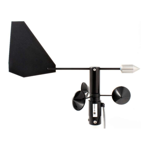
Novalynx
Novalynx 200-WS-02 Series User manual

Novalynx
Novalynx 200-WS-23-DP User manual

Novalynx
Novalynx 200-WS-02 Series User manual
Novalynx
Novalynx 200-WS-03D User manual
Novalynx
Novalynx 225-WS-32THA User manual
Novalynx
Novalynx 200-WS-01B User manual
Novalynx
Novalynx 230-600C User manual

Novalynx
Novalynx 200-WS-01B User manual
Novalynx
Novalynx 200-WS-04 User manual
