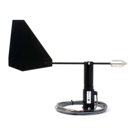
Novalynx 200-WS-03D User manual

NOVALYNX CORPORATION
MODEL 200-WS-03D
WIND & TEMPERATURE SENSOR
INSTRUCTION MANUAL

ii
Receiving an Unpacking
Carefully unpack all components and compare to packing list. Notify NovaLynx
Corporation immediately concerning any discrepancy. Inspect equipment to detect any
damage that may have occurred during shipment. In the event of damage, any claim for
loss must be filed immediately with the carrier by the consignee. amages to equipment
sent via Parcel Post or UPS require the consignee to contact NovaLynx Corporation for
instructions.
Returns
If equipment is to be returned to the factory for any reason, call NovaLynx between 8:00
A.M. and 4:00 P.M. Pacific Time and request a Return Authorization Number (RA#).
Include with the returned equipment, a description of the problem and the name, address,
and daytime phone number of the sender. Carefully pack the equipment to prevent
damage or additional damage in the return shipment. Call NovaLynx for packing
instructions in the case of delicate or sensitive items. If packing facilities are not available
take the equipment to the nearest Parcel Post, UPS, or freight service and obtain
assistance with the packaging. Write the RA# on the outside of the box.
Warranty
NovaLynx Corporation warrants that its products are free from defects in material and
workmanship under normal use and service for a period of one year from the date of
shipment from the factory. NovaLynx Corporation's obligations under this warranty are
limited to, at NovaLynx's option: (i) replacing; or (ii) repairing; any product determined to
be defective. In no case shall NovaLynx Corporation's liability exceed product's original
purchase price. This warranty does not apply to any equipment that has been repaired or
altered, except by NovaLynx Corporation, or that has been subjected to misuse,
negligence, or accident. It is expressly agreed that this warranty will be in lieu of all
warranties of fitness and in lieu of the warranty of merchantability.
A ress
NovaLynx Corporation
4055 Grass Valley Highway, Suite 102
Auburn, CA 95602
(530) 823-7185
FAX (530) 823-8997
Copyright © , 1997 by NovaLynx Corp.

1
MODEL 200-WS-03D
WIND & TEMPERATURE SENSOR
1.0 INTRODUCTION
This manual contains information to aid in the design of custom interface circuits for use
with the NovaLynx Model 200-WS-03 combination Wind and Temperature Sensor. This
information is supplied to systems integrators with the express understanding that
NovaLynx Corporation assumes no responsibility or liability for the operation of the sensor
as a part of any equipment that has been designed or furnished by any organization other
than NovaLynx.
The Model 200-WS-03 Wind and Temperature Sensor assembly consists of three major
parts: an anemometer for measuring wind speed; a wind vane for measuring horizontal
wind direction; a thermistor temperature sensor. The complete sensor assembly has been
designed with the wind vane mounted on top of the anemometer for stability and ease of
signal transmission. A small white shield protects the thermistor from direct solar heating
and is located on the side of the sensor where the thermistor passes through the sensor
housing. Output signal transmission is accomplished through a forty-foot length of six-
conductor, twenty-six gauge, flat cable. The cable has been terminated by a six-pin RJ-11
connector. Monitoring equipment supplied by NovaLynx will be equipped with a matching
connector receptacle.
1.1 ANEMOMETER
The anemometer uses a three-cup hub and cup assembly to sense wind velocity. As the
wind blows past the cups, the pressure of the wind against the insides of the cups causes
them to rotate. There are three permanent magnets embedded in the hub that holds the
cups. Each magnet, as it rotates past a fixed point on the sensor base, activates a
magnetic reed switch mounted in the base. Three closures of the reed switch will be
produced for each revolution of the cup assembly. The contacts of the magnetic reed
switch capsule are normally open; the contact will close each time a magnet passes over
it. The ratio of closed-to-open time is nominally 1/10 of the total period for a revolution of
the wind cups. This duty cycle may change slightly as the sensor ages and with exposure
to temperature extremes.
The anemometer is rated for wind speeds up to 125 miles per hour and has a starting
threshold of approximately 1 mile per hour. The magnetic reed switch capsule is rated to
carry a maximum current of 10.0 milliamperes with an applied voltage of no more than 50
volts AC or C. The approximate speed constant for the anemometer is 1.25 mph/Hz.

2
1.2 WIND VANE
The wind vane is coupled to a 20K ohm, ±20%, single turn potentiometer. The linearity of
the potentiometer is ±1%. Maximum power dissipation should be limited to 1/4 watt.
Resolution is infinite over potentiometer's 355 degree arc. There is a gap ("dead band")
of approximately 5 degrees between the ends of the resistive media. As the wind blows
past the vane, the design of the counter-weight and the tail fin align the point of the
counter-weight into the wind. Fluctuations in the wind direction are measured by the
sensor as the aerodynamics of the counter-weight and the tail try to keep aligned to the
path of the wind. The motion of the wind vane is translated to the potentiometer shaft
causing a change in the potentiometer's resistance. Connecting the potentiometer wires
to a voltage source allows easy measurement of the wind direction as a change in voltage.
1.3 TEMPERATURE
The ambient air temperature is measured by using a thermistor that is mounted inside the
protective shield located on the side of the sensor base. The thermistor exhibits rapid
changes in its resistance in response to temperature changes. The resistance change is
inversely proportional to the temperature. By using precision scaling and linearization
resistors in a bridge circuit, the resistance changes of the thermistor can be converted into
a voltage that can be easily calibrated and monitored. The thermistor's resistance vs.
temperature data can be found in Table 1.
2.0 SPECIFICATIONS
Anemometer:
Turning Radius: 3" to center of cup
Speed Threshold: 1.2 mph
Transducer Type: Reed Switch, Magnet Activated
Speed Constant: 1.25 mph = 1 Hz
Measurement Range: 0-100 mph
Accuracy: 1 mph or ±3%

3
Win Vane:
Azimuth Accuracy: ±3°
Bearing Type: Bushing
Potentiometer Gap: 5° Approximately
istance Constant: 1.5'
amping Ratio: 0.4
Vane Threshold: 1.2 mph
Measurement Range: 0-360 egrees Azimuth
Turning Radius: 10 1/2"
TEMPERATURE:
Accuracy: ±0.4F (0.2° C)
issipation: 2.5mW
issipation Factor: 7mW/°C
Operating Temperature: -40° to +150°F
(-40 to +60° C)
Thermal Time Constant: 11 seconds in still air ( approx )
COMPLETE SENSOR:
Total Size: 12" H x 17" W
Cable: 40' - 6 Cond 26 AWG
Connector: 6-Pin RJ-11
Mounting: 1-1/16"O. . pipe (standard 3/4" pipe)
Total Weight/Shipping: 2 lb / 4 lbs

4
3.0 INSTALLATION
3.1 LOCATION
Choose a mounting location for the wind sensor assembly that is free of obstructions.
Nearby objects can create eddy currents that will seriously affect the wind measurements.
Try to locate the wind sensors so that the nearest object is 10 x T away from the wind
sensor mast. T is the height of the object. If the sensors are located on top of a building,
the sensor height should be 1.5 x H, where H is the height of the building. Avoid overhead
power lines whenever possible. If there are overhead power lines, use extreme care to
prevent contact with the power lines while installing the equipment. Roof mounted sensors
should be placed on the upwind side of the building and away from all exhaust vents. In
all cases, if the wind sensor data is to be correlated to National Weather Service data or
World Meteorological Organization data, then the standard exposure is 33 feet (10 meters)
above the ground.
WARNING: Use extreme caution to avoid contacting overhead electrical power lines
during the anemometer installation. NovaLynx recommends using only
experienced equipment installers to avoid injury and serious problems.
3.2 Mounting
Typically, the Model 200-WS-03 sensor is mounted onto a pipe or a mast. A mast size
of 1" to 1-1/16" outside diameter works best. If the pole is metal it should be properly
grounded to minimize lightning damage. It may be necessary in some locations to contact
a local contractor to ensure that local electrical codes have been met by the installer. The
mast should be easy to reach for servicing the sensor and should be properly anchored
and grounded. Position the sensor onto the end of the mast. Secure the sensor to the
mast using the set screws provided in the sensor base. At this point leave the base set
screws loose until after the sensor has been aligned to North. o not use excessive force
when tightening the screws. Simply tighten the screws until the sensor base can no longer
be manually rotated.
3.3 SENSOR ALIGNMENT TO NORTH
The Wind Vane requires alignment of the "dead band" or potentiometer gap to North,
either magnetic or True North, to obtain valid measurements. Alignment can be done at
ground level allowing easier installation of the sensor, but it must be checked again after
the sensor has been fully installed. The Wind Sensor base is used to orient the wind vane
to North. Normally, wind direction sensors are aligned to True North, rather than Magnetic
North. True North is usually found by reading a magnetic compass and applying the
correction for magnetic declination, where magnetic declination is the number of degrees
between True North and Magnetic North.

5
Wind Vane alignment can be performed using a compass. Alignment involves creating an
imaginary line running through the wind sensor from North to South. When this line has
been established, the mounting base of the sensor is rotated until the screw head in the
base and the screw hole that is just above it in the sensor body both point toward North.
Rotate the sensor housing until the two screw holes point toward the North. Rotate the
vane tail until the counter-weight nose also points to North and is in line with the two screw
holes. Check the output signal of the direction sensor. If the alignment is correct, the
output signal should indicate North ( 355.0 or 0.00 egrees ). Correct the sensor base
rotation to bring the reading into agreement with the compass. When the alignment
appears to be good, secure the sensor base set screws to the mast.
3.4 SIGNAL CABLE INSTALLATION
The sensor signal cable is routed down the mast and to the monitoring equipment in the
most direct manner. Fasten the cable to the mast to protect the cable from damage during
high velocity winds. For best results, use plastic cable ties that are resistant to ultra-violet
radiation and place them at two foot intervals. Along areas where there is no mast or there
is some other type of support structure, use the most appropriate method available to
fasten the cable to the support. Use care when installing the cable to avoid sharp bends,
excessive twisting, scrapes and nicks. Additional cable protection can be provided by
using plastic or metal conduit.
4.0 SENSOR CALIBRATION
Calibration of the Wind & Temperature Sensor is limited to checking of the three sensors'
performance. Contact NovaLynx for assistance whenever a sensor appears to be out of
its specified calibrated range.
4.1 ANEMOMETER CALIBRATION
Spin the cups by hand and monitor the output signal wires using an ohmmeter. There
should be three switch closures for each revolution of the cups. The ohmmeter should
show transitions from infinite resistance to zero resistance during each switch closure. If
the ohmmeter is equipped with an audible cable test function, use the cable test mode and
count the beeps per revolution.
Anemometer calibration can be checked by comparing the anemometer's output signal to
that of an anemometer that has recently been calibrated or used as a testing standard. An
anemometer can also be checked by placing it into a wind tunnel and comparing the wind
tunnel velocity against the anemometer's output signal. A non-contacting tachometer can
also be used to verify anemometer performance.

6
4.2 WIND VANE CALIBRATION
Wind Vane calibration involves checking the potentiometer output and verification of the
sensor alignment to North.
NovaLynx recommends that the sensor alignment be verified before attempting the sensor
calibration testing. Use the procedure described in step 3.3 to verify sensor alignment to
North. After doing the alignment check and making any necessary adjustments, test the
sensor potentiometer. The potentiometer test may be done with the sensor installed on
the mast or with the sensor removed.
To test the Wind Vane potentiometer, monitor the sensor output wires using an ohmmeter,
or use the data logging equipment to record the sensor output during the test. If the
ohmmeter is used, disconnect the sensor signal wires from the monitoring or data logging
equipment. Starting at the North point, slowly rotate the sensor in a clockwise direction as
viewed from above the sensor. Looking at the potentiometer with an ohmmeter, the
readings should start at or near zero resistance and increase to 20,000 ohms as the sensor
is rotated. The resistance changes should be smooth and gradual without any
discontinuities. The sensor output should be approximately 56 ohms per degree of
horizontal wind. The maximum resistance reading should appear at 355 degrees azimuth.
After 355 degrees, the potentiometer's dead band is entered by the wiper and the
ohmmeter reading should float and not read any specific resistance. After 5 degrees of
motion, the readings should begin at zero again.
Correction of the wind direction potentiometer setting involves disassembly of the sensor
and rotation of the potentiometer shaft from inside the sensor housing. o not attempt to
make this adjustment unless the correct tools and test equipment are available. Please
contact NovaLynx for assistance before attempting to adjust the sensor.
To adjust the potentiometer gap position setting, first remove the vane tail and hub
assembly from the sensor by removing the small set screw located on one side of the hub.
With the screw removed, slide the hub up and off the potentiometer shaft. Note that the
potentiometer body is bonded to the sensor body and should not move. Using an
ohmmeter to monitor the potentiometer output, turn the potentiometer shaft until the center
of the gap is obtained. At this point, carefully lower the hub back onto the potentiometer
shaft. Try to avoid moving the shaft. With the hub in place reinstall the set screw. o not
over tighten the set screw. Check the sensor calibration after the hub has been reseated.
One recommended method of calibrating and checking the calibration is to point the nose
to South and measure 180° (approx. 10000 ohms). This method may be more accurate
and easier to do for some technicians since there is a more stable reading available at
180° than there is when the potentiometer wiper is in the dead band. Several attempts
may be necessary to get the exact results needed. Remember to check the calibration
setting again after the hub has been reinstalled. Use care to avoid putting the hub on
backwards.

7
4.3 TEMPERATURE SENSOR CALIBRATION
Calibration of the temperature sensor is limited to checking the operating range of the
sensor. There are no user adjustments available for the temperature sensor.
Check the thermistor operation by comparing the signal at the monitoring equipment
against the temperature readings of a precision thermometer. This procedure assumes
that the monitoring equipment has already been properly calibrated and is working
perfectly.
Ambient temperature readings should be taken by placing a precision thermometer next
to the thermistor shield. Leave the thermometer next to the thermistor long enough for a
stable reading to be made.
If ambient temperature readings are difficult to make right at the thermistor, place the
thermometer at a point that is as close to the thermistor as possible. Try to shield the
thermometer from direct solar heating during the readings. For readings made in this
manner, an agreement of 1 to 2 degrees Fahrenheit would be acceptable.
Increased testing accuracy requires taking the sensor assembly down from its mast and
placing the entire sensor into a chamber with a stable temperature. The chamber should
be equipped with a precision temperature sensor or a thermometer must also be placed
into the chamber next to the thermistor. Again, compare the temperature reading of the
thermistor to that of the precision thermometer. Agreement between the two temperatures
should be close to if not better than the specified accuracy of the thermistor (±0.4° F).
Any thermistor that appears to be out of calibration or that is inoperative must be replaced
by NovaLynx. Contact NovaLynx to arrange for repair of the sensor.
Remember that when the Wind & Temperature Sensor assembly is reinstalled onto its
mast that it should be re-aligned to North.
5.0 SENSOR MAINTENANCE
Maintenance of the Wind & Temperature Sensor assembly is limited. Periodic but regular
inspections of the equipment is necessary to prevent damage due to loose or missing
hardware. Tower and mast mounted sensors experience many vibrations due to high
velocity winds blowing through the tower and mast support structure. These vibrations can
cause mounting hardware to become loose and to fall out. Tighten any loose hardware
and replace any missing hardware.

8
Inspect the sensor cable as well to detect any damage due to wind whipping. Replace any
damaged cables immediately, especially if there are exposed wires. Cracked and
weathered cable jackets are not usually a problem as long as the cable is securely
fastened by wire ties. Check wire ties and replace any that have become loose or that are
missing.
Check for damage to the anemometer cups and the vane tail. Replace any cup assembly
that has been damaged.
Apply several drops of light weight ( 3 IN 1 ) machine oil or lightly spray W 40 onto the
anemometer bearing located just below the cups.
Remove all dust, dirt, mud, bird droppings, etc. that may have been deposited onto the
cups and vane tail. Repair or replace bent tails. Check the counterweight of the wind
direction sensor. Repair the vane shaft if the counterweight is loose. The counterweight
is held in place by epoxy.
Remove any debris that may become lodged inside the temperature shield. Rinse off the
thermistor bead with clean water.
Always look at the Wind Vane alignment to North. If the alignment is critical, do the check
with a compass. Make corrections to the alignment as needed. Always check the
alignment after a severe storm with high velocity winds.
Check the equipment that the sensor assembly is connected into. Make sure that there
are signals coming from the sensors. Test the signals to be certain that the measurements
are accurate.
For critical measurements, a second sensor should be stored nearby for immediate
replacement should the primary sensor become damaged or disabled.
Contact NovaLynx for assistance with sensor testing or for help with replacement sensors
and spare parts.

9
TEMPERATURE VS. RESISTANCE DATA FOR THERMISTOR
TABLE 1
TEMPERATURE
egrees C
RESISTANCE
Kohm
-40 328.4
-35 237.7
-30 173.9
-25 128.5
-20 95.89
-15 72.23
-10 54.89
-5 42.07
0 32.51
5 25.31
10 19.86
15 15.69
20 12.49
25 10.00
30 8.060
35 6.536
40 5.331
45 4.373
50 3.606
55 2.989
60 2.490
65 2.085
70 1.753
Table of contents
Other Novalynx Accessories manuals
Novalynx
Novalynx 200-WS-02 Series User manual
Novalynx
Novalynx 200-WS-01B User manual
Novalynx
Novalynx 230-600C User manual
Novalynx
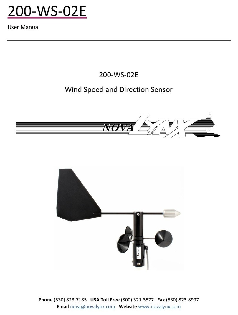
Novalynx 200-WS-02E User manual

Novalynx
Novalynx 200-WS-22 User manual
Novalynx
Novalynx 255-100 User manual

Novalynx
Novalynx 200-WS-01B User manual
Novalynx
Novalynx 225-WS-32THA User manual
Novalynx
Novalynx 200-WS-23 User manual
Novalynx
Novalynx 225-HMP60A User manual
