I-novative Factory-Link-SPE-G User manual
User Manual
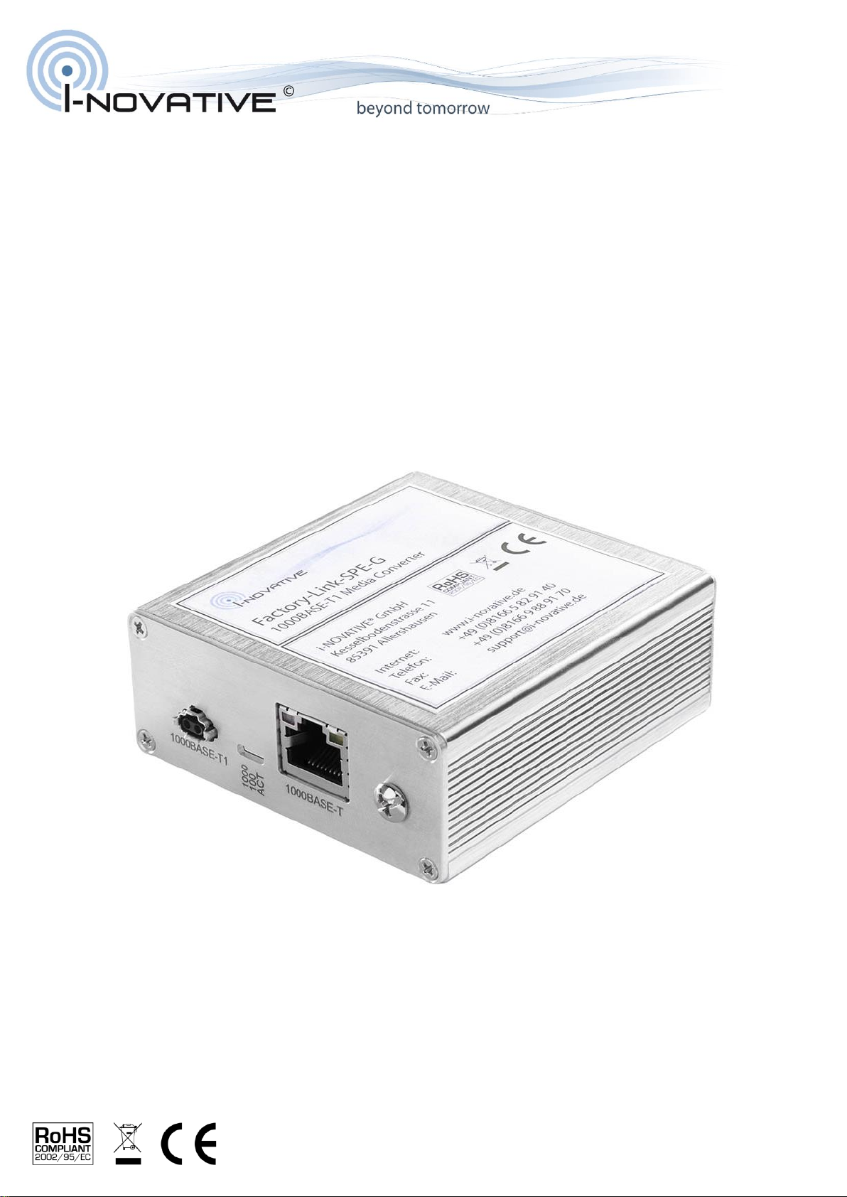
Factory-Link-SPE-G
Industrial SPE 1000BASE-T1 Media Converter
INO_Factory-Link-SPE-G_User_Manual_V1.0.docx

INO_Factory-Link-SPE-G_User_Manual_V1.0.docx
2022-09-10
2 / 12
Table of Contents
Revision History ...................................................................................................................................... 3
1Introduction ...................................................................................................................................... 4
2Technical Data.................................................................................................................................. 4
2.1 Features.................................................................................................................................... 4
3Scope of Delivery ............................................................................................................................. 5
4Intended Purpose and Disclaimer..................................................................................................... 5
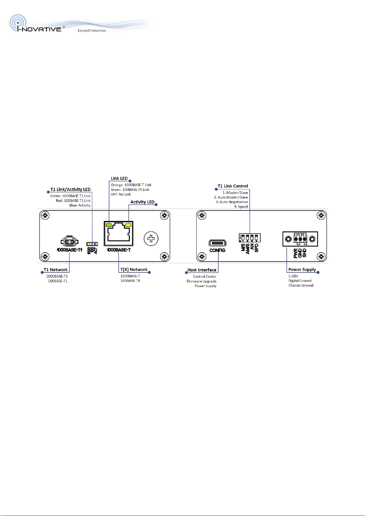
5Connectors and Cables.................................................................................................................... 5
5.1 1000BASE-T1 / 100BASE-T1 IEC 63171-6 Connector ............................................................. 5
5.1.1 T1-Plug Specification ......................................................................................................... 5
5.1.2 Pin Assignment .................................................................................................................. 5
5.1.3 T1 Cable Recommendation................................................................................................ 6
5.2 Power Connector ...................................................................................................................... 6
5.2.1 Receptacle Specification.................................................................................................... 6
5.2.2 Pin Assignment .................................................................................................................. 6
5.2.3 Power Cable Recommendation.......................................................................................... 6
6Configuration.................................................................................................................................... 7
6.1 T1 Role (DIP1) .......................................................................................................................... 7
6.2 Auto Role Switch (DIP2)............................................................................................................ 7
6.3 Auto-Negotiation (DIP3) ............................................................................................................ 7
6.4 Speed (DIP4) ............................................................................................................................ 8
6.5 1000BASE-T / 100BASE-TX Link.............................................................................................. 8
7Software........................................................................................................................................... 9
7.1 Controller Functions .................................................................................................................. 9
7.2 T1 Functions ........................................................................................................................... 10
Link Monitoring ........................................................................................................................... 10
Cable Diagnostics....................................................................................................................... 10
Register Access.......................................................................................................................... 10
7.3 T(X) Functions .........................................................................................................................11
8Important Information ..................................................................................................................... 12
8.1 Packaging Ordinance.............................................................................................................. 12
8.2 Recycling Reference and RoHS Compliance .......................................................................... 12
8.3 CE Marking ............................................................................................................................. 12
9Manufacturer and Support.............................................................................................................. 12
10 Warranty..................................................................................................................................... 12

INO_Factory-Link-SPE-G_User_Manual_V1.0.docx
2022-09-10
3 / 12
Revision History
Revision
Date
Change
1.0
09/03/2022
initial release version
INO_Factory-Link-SPE-G_User_Manual_V1.0.docx
2022-09-10
4 / 12
1 Introduction
The Factory-Link-SPE-G connects 1000BASE-T1 with 1000BASE-T networks as well as 100BASE-T1
with 100BASE-TX networks. With an inductive T1 frontend, chassis grounding, and extra ESD protection
of the network links, it is designed for industrial environments. The IEC 63171-6 compliant T1-connector
makes it a plug-and-play solution for industrial Single Pair Ethernet. It supports 802.3bp auto-negotiation
and proprietary master/slave detection. Master/slave role, speed and auto-negotiation modes can be set
via DIP switches. The Control Center software connects via the USB-C interface to the Factory-Link-
SPE-G and provides information about link state and signal quality and allows direct PHY register
access. Faults in the T1 connection can be detected using the Signal Quality Indicator and the Cable
Diagnostics function allowing shortcut, open connection, and fault distance detection. The Factory-Link-
SPE-G is equipped with a dual power supply that seamlessly switches between the dedicated power
port and USB. On the power connector, it supports a wide input voltage range from 5V to 28V. The
housing can be grounded using either the power connector or the grounding screw.
2 Technical Data
2.1 Features
•Standards: IEEE802.3bp, IEEE802.3bw, IEEE802.3ab, IEEE802.3u
•1000BASE-T1 / 100BASE-T1 Port (T1 Industrial Jack AH IP20, IEC 63171-6 compliant)
•1000BASE-T / 100BASE-TX Port (RJ45)
•USB-C Port (Control Center, Firmware Update, Power Supply)
•DIP Switch for Master/Slave, Speed, Auto-Negotiation Setting
•Automatic Master/Slave-Detection (proprietary)
•802.3bp Auto-Negotiation
•802.3bp Link Type-A (15m TP)
•Cable Diagnostics (T1 connection: open, short, fault distance)
•Aluminum Housing with grounding screw
◦Dimensions: 74 x 30 x 82 mm (width x height x depth)
•Power Supply
◦PWR Conn (3Pos Terminal Block): DC 5V – 28V
◦USB-C: DC 5V
◦Chassis grounding via Grounding Screw and/or SHD contact in PWR Conn
•Power Consumption: < 150mA @ 12V
•Environmental Temperature Range: -40°C - +65°C
INO_Factory-Link-SPE-G_User_Manual_V1.0.docx
2022-09-10
5 / 12
•T1 ESD Protection
◦IEC 61000-4-2 (ESD) 25kV (Air), 25kV (Contact)
•TX Surge and ESD Protection
◦IEC 61000-4-2 (ESD) ±30 kV (Air/Contact)
◦IEC 61000-4-5 (Lightning) 45 A (8/20 µs)
•USB ESD Protection
◦IEC 61000-4-2 (ESD) ±15 kV (Air) / ±8 kV (Contact)
•Network Interfaces (PHYs)
◦1000BASE-T1 / 100BASE-T1 PHY: Broadcom BCM89881
◦1000BASE-T / 100BASE-TX PHY: Broadcom BCM54811
3 Scope of Delivery
•Factory-Link-SPE-G (Industrial SPE 100BASE-T1 Media Converter)
•Power Connector Receptacle (3Pos Terminal lock Plug)
•USB Cable (USB-A to USB-C)
4 Intended Purpose and Disclaimer
Disclaimer: The products sold by i-novative® GmbH are for development and testing purposes in
automotive or industrial applications only. The product Factory-Link-SPE-G is not intended to be used in
series application or series production.
Warranty Exclusion: i-novative® GmbH does not take over any liability for defects associated with the
product and installation of that product. Our product warranty does not cover problems that result from
abuse, accident, misuse, or problems with electrical power. It does not cover uses not in accordance with
the instruction manual. It does not cover commercial use of the product.
5 Connectors and Cables
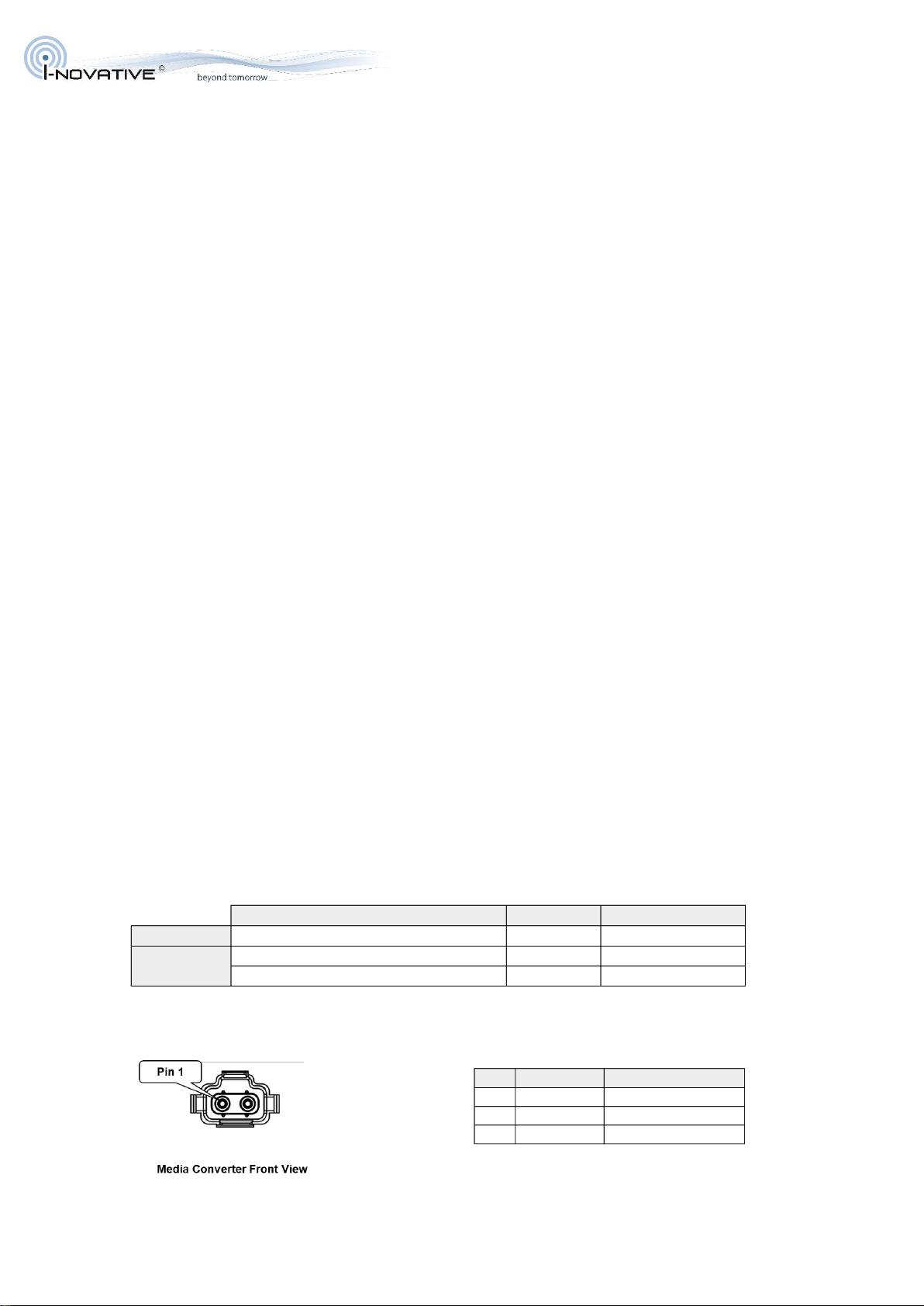
5.1 1000BASE-T1 / 100BASE-T1 IEC 63171-6 Connector
5.1.1 T1-Plug Specification
5.1.2 Pin Assignment
1000BASE-T1
Pin Signal Remark
1 Data P
2 Data N
SHD Shield Connector Housing
Description Vendor Part Number
Mating Plug T1 Industrial plug SL-C IP20 Harting 09 45 181 2810 XL
T1 male crimp AWG 26-28 Harting 09 45 500 2810
T1 male crimp AWG 22-24 Harting 09 45 500 2812
Terminals

INO_Factory-Link-SPE-G_User_Manual_V1.0.docx
2022-09-10
6 / 12
5.1.3 T1 Cable Recommendation
For proper operation of the link, the used network cables and connectors for the T1 link must comply to
the specifications of the respective standards. Please refer to:
•100BASE-T1: “IEEE 802.3bw Clause 96.7”
•1000BASE-T1: “IEEE 802.3bp Clause 97.6”
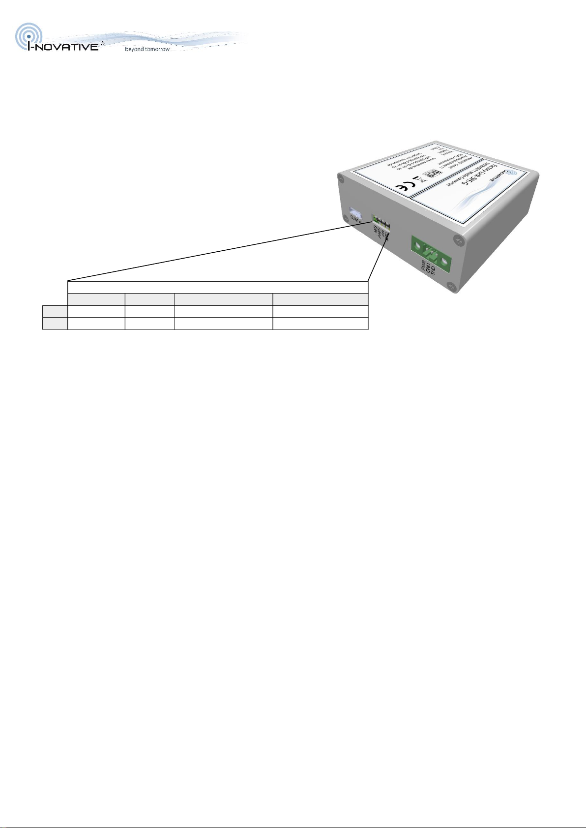
5.2 Power Connector
5.2.1 Receptacle Specification
5.2.2 Pin Assignment
5.2.3 Power Cable Recommendation
Description Manufacturer Structure Jacket Shield AWG
T1 SPE IP20 1x2xAWG26/7 PUR 15m Harting
2x0,13mm2yes yes AWG26
Dacar 676 Leoni
2x0,14mm2yes yes AWG26
Dacar 645 Leoni
2x0,17mm2yes yes AWG25
Dacar 646 Leoni
2x0,35mm2yes yes AWG22
FL09YBCY Kromberg & Schubert
2x0,14mm2yes yes AWG26
FLCUSN9Y-9YBCY Kromberg & Schubert
2x0,13mm2yes yes AWG26
T1 SPE IP20 1x2xAWG26/7 PUR 15m Harting
2x0,13mm2yes yes AWG26
Dacar 547 Leoni
2x0,13mm2yes no AWG26
Dacar 626 Leoni
2x0,14mm2yes no AWG26
Dacar 546 Leoni
2x0,35mm2yes no AWG22
Dacar 624 Leoni
2x0,35mm2no no AWG22
Dacar 617 Leoni
2x0,17mm2no no AWG25
FLR9Y-31Y Kromberg & Schubert
2x0,35mm2yes no AWG22
FLKCuMgU9Y-9Y Kromberg & Schubert
2x0,13mm2yes no AWG26
FLCUSNU9Y-31Y Kromberg & Schubert
2x0,13mm2yes no AWG26
1000BASE-T1
100BASE-T1
Description Vendor Part Number Distributor Distributor Number
Mating Plug
3Pos Terminal Block Plug 2.5mm
180° free hanging
Würth
Elektronik
691381030003 Digi-Key 732-6056-ND
Pin Signal Remark
1 PWR (+) 5V - 28V DC
2 GND (-)
3 SHIELD Chassis GND
Description Manufacturer Structure Jacket Shield Remarks
FLRY 2x0,35-B RD/BL Leoni
2x0,35mm2no no AWG22
FLRY-B 1x0,35 RD Leoni
1x0,35mm2no no AWG22
FLRY-B 1x0,35 BL Leoni
1x0,35mm2no no AWG22
Power
Supply
INO_Factory-Link-SPE-G_User_Manual_V1.0.docx
2022-09-10
7 / 12
6 Configuration
Using the DIP switches, you can configure the master / slave role, speed and auto-negotiation modes of
the T1 port.
6.1 T1 Role (DIP1)
DIP1 configures the T1 link role either to Master (ON) or Slave (OFF). If Auto Role Switch is active
(DIP2=ON; DIP3=OFF) it has no effect. If Auto-Negotiation (DIP3) is turned on DIP1 controls the
preferred role being advertised during auto-negotiation.
6.2 Auto Role Switch (DIP2)
DIP2 controls a proprietary Auto Role Switch function. When turned on, the Factory-Link-SPE-G
automatically determines the T1 link role (master or slave). This function is for easily connecting to link
partners not supporting 802.3bp Auto-Negotiation or having it turned off. This switch is ignored when
Auto-Negotiation (DIP3) is turned on.
The Auto Role Switch feature can increase the link setup time.
Do not connect the T1 interfaces of two Factory-Link-SPE-G with activated Auto Role Switch on both
sides. This may prevent the link establishment.
6.3 Auto-Negotiation (DIP3)
DIP3 turns the 802.3bp Auto-Negotiation feature on and off. When enabled, T1 link role (Master/Slave)
and the link speed (1000/100Mbit/s) are automatically negotiated between the link partners. For proper
operation, both link partners must support 802.3bp Auto-Negotiation and have it turned on.
When Auto-Negotiation is enabled at the Factory-Link-SPE-G, Auto Role Switch (DIP2) is turned off and
DIP4 (Speed) controls the speed that is being advertised (OFF: 100Mbit/s; ON: 100Mbit/s and
1000Mbit/s). The effective link speed is determined between the link partners by the auto-negotiation
protocol. The Auto-Negotiation Preferred Role is determined by the setting of DIP1.
1 2 3 4
OFF Slave Fixed Role 802.3bp Auto-Neg off 100BASE-T1 Mode
ON Master Auto Role 802.3bp Auto-Neg on 1000BASE-T1 Mode
DIP Switch

INO_Factory-Link-SPE-G_User_Manual_V1.0.docx
2022-09-10
8 / 12
6.4 Speed (DIP4)
DIP4 controls the link speed. If Auto-Negotiation (DIP3) is turned off, it directly sets the link speed to
either 100Mbit/s (OFF) or 1000Mbit/s (ON). With activated Auto-Negotiation, DIP4 controls the
advertised link speed (OFF: 100Mbit/s; ON: 100Mbit/s and 1000Mbit/s).
6.5 1000BASE-T / 100BASE-TX Link
At the “legacy” Ethernet side (RJ45 port), the Factory-Link-SPE-G is configured for Auto-Negotiation and
follows the link speed of the T1 side. If the T1 link is established with 1000Mbit/s, the Factory-Link-SPE-
G advertises 1000Mbit/s and if the T1 link is established with 100Mbit/s, the Factory-Link-SPE-G
advertises 100Mbit/s.
INO_Factory-Link-SPE-G_User_Manual_V1.0.docx
2022-09-10
9 / 12
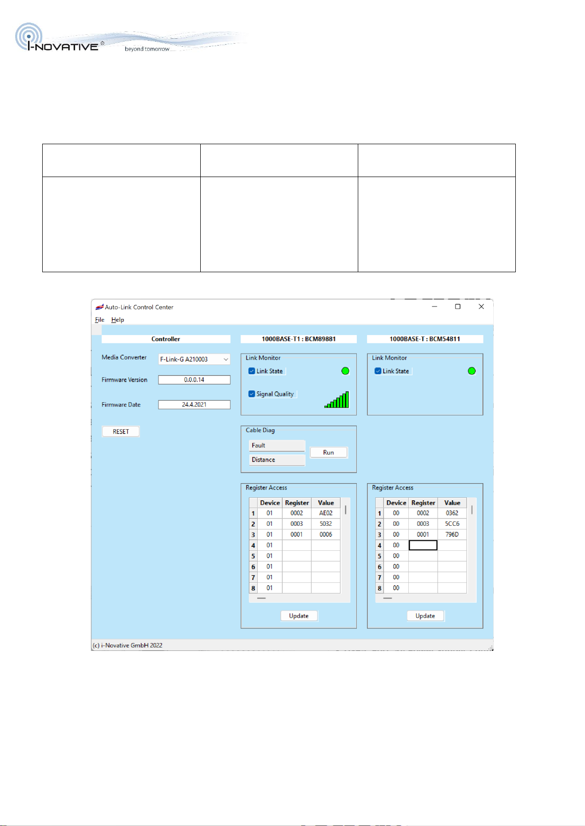
7 Software
The graphical user interface is intended for remote monitoring. It can also be used for testing and
development purposes since it provides direct access to the register sets of the integrated PHYs. It
provides the following functions:
Controller
1000BASE-T1
100BASE-T1 connection
1000BSE-T
100BASE-TX connection
•Media Converter Selection
•Firmware Information
•Device Reset
•Link Status Monitoring
•Signal Quality Indicator
(SQI) Monitoring
•Cable Diagnostics
•Read/Write Access to PHY
registers
•Link Status Monitoring
•Read/Write Access to PHY
registers
7.1 Controller Functions
If you have attached multiple i-novative® Media Converters to the same host via the USB configuration
port, you can connect the UI to a specific one using the drop-down list. The Media Converters are
distinguished by their type and USB serial number.

INO_Factory-Link-SPE-G_User_Manual_V1.0.docx
2022-09-10
10 / 12
When an i-novative® Media Converter is selected, its firmware revision and firmware date are read out
and displayed in the respective fields.
Using the RESET button, the Media Converter is re-initialized to its default state.
7.2 T1 Functions
Link Monitoring
The UI provides continuous monitoring of T1 link state and SQI (Signal Quality Indicator). Using the
checkboxes, you can enable and disable the respective functions.
The bars of the SQI bar-graph represent the exact SQI values ranging from SQI=0 to SQI=7. SQI needs
to be 1 or higher for proper operation of the link.
Cable Diagnostics
Using the T1 PHY Automotive Cable Diagnostics, cable faults and their distance from the device can be
detected. During the measurement, the link is broken. The distance measurement has a tolerance of
±1.5m. ACD can detect broken wires (OPEN) and intra-pair shorts (SHORT). In case of an INVALID
result, try to repeat the measurement. PAIR BUSY indicates traffic on the pair. Turn off the link partner in
order to get a valid result.
Register Access
The Register Table allows to read and write PHY registers directly. Modifying the register settings can
impact the Media Converter functionality. All changes are transient and are lost after resetting or power
cycling the device. Please use this function only if you do have the required knowledge. The software
prevents write access to registers which can impact the hardware configuration. For a documentation of
the PHY registers contact the PHY vendor.
The Register Table is laid out for Clause 45 MDIO access.
Device
Specifies the Clause 45 device address. The values are preconfigured and be
selected by right-clicking a respective field.
Register
Is the PHY Register address according to Clause 45. Entering a value and pressing
ENTER or TAB will read the respective register.
Value
Represents a PHY register value that has been read entering the address data in the
Device and Register fields. Entering a value in this field will result in a write operation
to the respective register. Written values are read back and displayed for a validation
of the write operation.
All entries are expected to be hexadecimal numbers.

INO_Factory-Link-SPE-G_User_Manual_V1.0.docx
2022-09-10
11 / 12
7.3 T(X) Functions
The “legacy” Ethernet PHY supports Link State Monitoring and Register Access like the T1 PHY. Please
refer to the previous section for a description.
The used BCM54811 PHY does not support Clause 45 MDIO addressing. The Device address is used
here to ease access to registers that need a specific access procedure.
00
1000BASE-T/100BASE-TX/10BASE-T Registers and Auxiliary Registers
18
Shadow 18 Registers: Enter the Shadow Selector in the Register field.
1C
Shadow 1C Registers: Enter the Shadow Selector in the Register field.
07
Clause 45 Registers
0D
Top Level Expansion Registers
0F
Expansion Registers

INO_Factory-Link-SPE-G_User_Manual_V1.0.docx
2022-09-10
12 / 12
8 Important Information
8.1 Packaging Ordinance
„Basically, manufacturers as well as distributors are obliged to ensure that sales packaging are
in principle taken back after use by the end user and recycled or reused.“ (according § 4 Satz 1
VerpackVO). If you as a customer have problems with the disposal of packaging and shipping
materials, please write an email to [email protected].
8.2 Recycling Reference and RoHS Compliance
Please note that parts of the products from i-novative® GmbH
must be properly recycled and must not be disposed with household waste
(i.e. circuit boards, power supply, etc.).
i-novative® products are RoHS compliant (RoHS = Restriction of
the use of certain hazardous substances; dt. „Restriction of use
certain dangerous substances“).
8.3 CE Marking
The i-novative® Factory-Link-SPE-G has the CE mark.
This device complies with the requirements of EU Directive: 89/336 / EC Directive
on electromagnetic compatibility and the mutual recognition of their conformity.
Conformity with the o.a. directive is confirmed by the CE mark.
9 Manufacturer and Support
i-novative® is a registered trademark of i-novative® GmbH. If you have questions concerning our
product, please contact us:
Manufacturer:
E-Mail:
i-novative® GmbH
Phone:
+49 8166 5 82 91 40
Kesselbodenstrasse 11
Fax:
+49 8166 9 88 91 70
85391 Allershausen
Internet:
www.i-novative.de
10 Warranty
Within the warranty period, we eliminate manufacturing and material defects free of charge.
For warranty issues please contact us via E-Mail: support@i-novative.de.
Table of contents
Other I-novative Media Converter manuals


