Novatech 1732 User manual

Oxygen Transmitter
Model 1732
Technical Manual
August 2018


August 2018 Technical Manual
1732 Oxygen Transmitter 1
TABLE OF CONTENTS
TABLE OF CONTENTS.................................................................................................................................... 1
1. IMPORTANT NOTICES ................................................................................................................................ 7
1.1 CAUTIONS.................................................................................................................................................. 7
1.2WARNING SYMBOLS.................................................................................................................................... 8
2. INTRODUCTION........................................................................................................................................... 9
2.1 THE 1732 TRANSMITTER............................................................................................................................. 9
2.2 SERIES 1230 OXYGEN PROBES &SENSORS.............................................................................................. 10
3. DEVICE SPECIFICATIONS........................................................................................................................ 11
3.1 HARDWARE SPECIFICATIONS..................................................................................................................... 11
3.1.1 Transmitter Specifications............................................................................................................... 11
3.1.2 Series 1230 Probes Specifications ................................................................................................. 12
3.1.3 Model 1234 Sampling Sensor Specifications.................................................................................. 13
3.1.4 Probe Ordering Information............................................................................................................. 13
3.2 OPERATIONAL SPECIFICATIONS................................................................................................................. 14
4. INSTALLATION AND COMMISSIONING .................................................................................................. 15
4.1 MOUNTING THE TRANSMITTER................................................................................................................... 15
4.2 INSTALLING A 1231 OXYGEN PROBE.......................................................................................................... 15
4.3 INSTALLING A 1234 OXYGEN SENSOR........................................................................................................ 17
4.4 INSTALLING THE AUXILIARY THERMOCOUPLE.............................................................................................. 17
4.5A SHIELD CONNECTIONS............................................................................................................................ 18
4.5B EARTH CONNECTION (PE)....................................................................................................................... 18
4.6 ELECTRICAL CONNECTIONS ...................................................................................................................... 19
4.7 HEATER INTERLOCK RELAYS..................................................................................................................... 21
4.8 CONNECTING AN OXYGEN PROBE CABLE................................................................................................... 22
4.9 CONNECTING A 1234 SENSOR CABLE........................................................................................................ 23
4.10 CONNECTING THE AUXILIARY THERMOCOUPLE (OPTIONAL)....................................................................... 23
4.11 CONNECTING THE OUTPUT CHANNELS..................................................................................................... 23
4.12 CONNECTING THE ALARMS...................................................................................................................... 23
4.13 CONNECTING THE AUTOMATIC PURGE AND CALIBRATION CHECK SYSTEM................................................. 24
4.14 CONNECTING REFERENCE AIR ................................................................................................................ 25
4.15 CONNECTING THE TRANSMITTER TO A MODBUS™ NETWORK.................................................................. 25
4.16 CONNECTING POWER ............................................................................................................................. 25
4.17 COMMISSIONING -RUN MODE ................................................................................................................. 26
4.18 PROBE OR SENSOR CALIBRATION............................................................................................................ 26
4.19 FILTER PURGING .................................................................................................................................... 26
4.20 CALIBRATION GAS CHECK....................................................................................................................... 26
4.21 DUST IN THE FLUE GAS........................................................................................................................... 27
4.22 STRATIFICATION ..................................................................................................................................... 27
4.23 CONNECTING A PRESSURE TRANSDUCER ................................................................................................ 27
5. DISPLAY AND KEYPAD ............................................................................................................................ 29
5.1 RUN MODE DISPLAY................................................................................................................................. 29
5.2 OXYGEN DISPLAY UNITS........................................................................................................................... 30
5.3 KEYPAD ................................................................................................................................................... 30
5.3.1 Keypad in Run Mode....................................................................................................................... 31
5.3.2 Keypad in the Setup / Commissioning / Calibration Menu.............................................................. 31
6. SETUP MENU ............................................................................................................................................. 33
6.1 FUNCTION SUMMARY TABLE...................................................................................................................... 33
6.2 SETUP MENU DISPLAY.............................................................................................................................. 33
6.3 CHANGING MENU OPTIONS....................................................................................................................... 33
6.4 SETUP MENU FUNCTIONS ......................................................................................................................... 34

Technical Manual August 2018
21732 Oxygen Transmitter
6.4.1 Probe 1 Offset ................................................................................................................................. 34
6.4.2 Lower Line Items............................................................................................................................. 34
6.4.3 Oxygen Display Units...................................................................................................................... 35
6.4.4 Damping Factor............................................................................................................................... 35
6.4.5 Process Alarms ............................................................................................................................... 35
7. COMMISSIONING MENU........................................................................................................................... 37
7.1 FUNCTION SUMMARY TABLE...................................................................................................................... 37
7.2 COMMISSIONING MENU FUNCTIONS........................................................................................................... 39
7.2.1 Internal Date / Time......................................................................................................................... 39
7.2.2 Service Date.................................................................................................................................... 39
7.2.3 Number of Probes ........................................................................................................................... 39
7.2.4 Probe 1 & 2 Type ............................................................................................................................ 39
7.2.5 Probe 1 & 2 Thermocouple Type .................................................................................................... 39
7.2.6 Auxiliary Thermocouple Type.......................................................................................................... 39
7.2.7 Transmitter Output Channel 1 & 2 .................................................................................................. 40
7.2.8 Flue Pressure Units......................................................................................................................... 40
7.2.9 Flue Pressure Input Units and Value .............................................................................................. 40
7.2.10 Temperature Units......................................................................................................................... 41
7.2.11 Calibration Freezes Outputs ......................................................................................................... 41
7.2.12 Solenoid 1 & 2 Operation.............................................................................................................. 41
7.2.13 Solenoid 1 & 2 Automatic / Manual............................................................................................... 41
7.2.14 Solenoid 1 & 2 Start Time ............................................................................................................. 41
7.2.15 Solenoid 1 & 2 Period.................................................................................................................... 41
7.2.16 Solenoid 1 & 2 Duration ................................................................................................................ 42
7.2.17 Solenoid 1 & 2 Post Freeze........................................................................................................... 42
7.2.18 Oxygen Content Calibration Gas 1 & 2......................................................................................... 42
7.2.19 Maximum Calibration Gas 1 & 2 Positive / Negative Error ........................................................... 42
7.2.20 Process Alarms ............................................................................................................................. 42
7.2.21 Alarm Relay 1, 2 and 3 Function................................................................................................... 42
7.2.22 Common Alarm Relay Function .................................................................................................... 43
7.2.23 Accepted Alarm Relay Hold .......................................................................................................... 43
7.2.24 Selecting the Correct Fuel............................................................................................................. 43
7.2.24 Reference Air Pump Options......................................................................................................... 44
7.2.25 Communications Port Options ...................................................................................................... 44
7.2.26 Alarm Log Clearing........................................................................................................................ 44
8. CALIBRATION MENU ................................................................................................................................ 45
8.1 FUNCTION SUMMARY TABLE...................................................................................................................... 45
8.2 CALIBRATION MENU FUNCTIONS................................................................................................................ 46
8.2.1 Reference Voltages......................................................................................................................... 46
8.2.2 Output Channel 1 and 2 Calibration................................................................................................ 46
8.2.3 Ambient Temperature Calibration ................................................................................................... 46
8.2.4 Low Oxygen Calibration.................................................................................................................. 46
8.2.5 Reference Air Probe 1 and Probe 2................................................................................................ 46
8.2.6 Transmitter Output Scale ................................................................................................................ 46
8.2.7 Transmitter Output Limiting............................................................................................................. 47
8.2.8 Mains Voltage Detection ................................................................................................................. 47
8.2.9 Heater SSR Fault Correction........................................................................................................... 47
8.2.10 SSR Fail Protection....................................................................................................................... 47
8.2.11 Burner Temp Override................................................................................................................... 48
8.2.12 Ref Pump Cycling.......................................................................................................................... 48
8.2.13 Dry Reference Air.......................................................................................................................... 48
9. ALARMS ..................................................................................................................................................... 49
9.1 CHECKING AND ACCEPTING AN ALARM....................................................................................................... 50
9.1.1 Current Alarms ................................................................................................................................ 50
9.1.2 Alarm Log........................................................................................................................................ 50
9.2 COMMON ALARMS .................................................................................................................................... 51
9.3 SELECTABLE PROCESS ALARMS................................................................................................................ 53
9.4 ALARM RELAY OPTIONS............................................................................................................................ 54

August 2018 Technical Manual
1732 Oxygen Transmitter 3
10. INSTRUMENT CALIBRATION ................................................................................................................. 55
10.1 CALIBRATION SUMMARY.......................................................................................................................... 55
10.1.1 Calibration of the Inputs ................................................................................................................ 55
10.1.2 Calibration of the Outputs.............................................................................................................. 55
10.1.3 Probe Calibration........................................................................................................................... 56
10.2 COLD START .......................................................................................................................................... 56
10.2.1 Forcing a Cold Start ...................................................................................................................... 56
10.2.2 Resetting the Calibration Factors.................................................................................................. 56
11. GAS CALIBRATION CHECK AND PURGE............................................................................................. 57
11.1 PURGE................................................................................................................................................... 57
11.2 CALIBRATION GAS .................................................................................................................................. 57
12. SOFTWARE UPGRADES......................................................................................................................... 59
13. TROUBLESHOOTING.............................................................................................................................. 61
13.1 FIRST APPROACH ................................................................................................................................... 61
13.2 DETAILED FAULT ANALYSIS..................................................................................................................... 61
14. MAINTENANCE........................................................................................................................................ 63
14.1 TRANSMITTER MAINTENANCE.................................................................................................................. 63
14.2 CLEANING .............................................................................................................................................. 63
14.3 REPLACEMENT PARTS............................................................................................................................. 63
15. INDEX........................................................................................................................................................ 64
APPENDIX 1, CONSTITUENT VALUES FOR VARIOUS FUELS................................................................. 65
APPENDIX 2, PROBE EMF TABLES ............................................................................................................ 66
APPENDIX 3, % OXYGEN SCALE TO LOGARITHMIC................................................................................ 68
APPENDIX 4, MODBUS™.............................................................................................................................. 69
END OF LIFE TREATMENT AND FINAL DISPOSAL................................................................................... 72

Technical Manual August 2018
41732 Oxygen Transmitter
Copyright NOVATECH CONTROLS PTY LTD —2018
This manual describes the transmitter firmware version 1.42, 12 June 2018
Neither the whole nor any part of the information contained in, or the product described in, this manual may
be adapted or reproduced in any material form except with the prior written approval of Novatech Controls
Pty Ltd (Novatech).
The product described in this manual and products for use with it are subject to continuous developments
and improvement. All information of a technical nature and particulars of the product and its use (including
the information in this manual) are given by Novatech in good faith. However, it is acknowledged that there
may be errors or omissions in this manual. A list of details of any amendments or revisions to this manual
can be obtained upon request from Novatech Controls Technical Enquiries. Novatech Controls welcome
comments and suggestions relating to the product and this manual.
All correspondence should be addressed to: -
Technical Enquiries
Novatech Controls Pty Ltd
309 Reserve Road, Tel: +61 3 9585 2833
Cheltenham Fax: +61 3 9585 2844
Australia Website: http://www.novatech.com.au/
Novatech Controls or their authorised dealers should carry out all maintenance and service on the product.
Novatech Controls can accept no liability whatsoever for any loss or damage caused by service or
maintenance by unauthorised personnel. This manual is intended only to assist the reader in the use of the
product, and therefore Novatech Controls shall not be liable for any loss or damage whatsoever arising from
the use of any information or particulars in, or any error or omission in, this manual, or any incorrect use of
the product.

August 2018 Technical Manual
1732 Oxygen Transmitter 5
Important Notice Regarding
1231 Probe Option - FIL-3
WARNING: The only identifiable standard for flame arresters for general use is British Standard BS EN
12874:2001. British Standard BS EN 12874:2001 refers to an operating environment up to 150 Degrees
Centigrade.
The FIL-3 device optionally fitted to 1231 Heated Zirconia Probes (the “Probes" or "Probe") operate in an
environment considerably greater than 150 Degrees Centigrade.
Therefore, we know of no Australian, British, European or USA standard applicable to flame arresters or their
testing above 150 degrees Centigrade. Consequently, the FIL-3 device cannot be certified as a safety
device.
The probe is only one of several potential sources of ignition. Extreme care is required when using the
probes during the start-up processes of a combustion appliance.
The Novatech Burner Interlock Relay facility, which is a standard part of the Novatech transmitter, is
designed to be wired to the main safety shut-off fuel valves in a way that can shutdown the probe heater
when the fuel valves are closed.
The risk of ignition of flammable gas mixture at the hot end of the Probe can only be minimised by correct
use, maintenance and operation of the FIL-3 device. The user of the FIL-3 device is responsible for
verification and maintenance and correct use and operation of the FIL-3 device.
THE USER AGREES THAT IT USES THE PROBE AND THE FIL-3 DEVICE AT ITS SOLE RISK.
NOVATECH CONTROLS PTY LTD, TO THE FULL EXTENT PERMITTED BY LAW, GIVES NO
WARRANTIES OR ASSURANCES AND EXCLUDES ALL LIABILITY (INCLUDING LIABILITY FOR
NEGLIGENCE) IN RELATION TO THE PROBE AND THE FIL-3 DEVICE.
The user must ensure that it correctly follows all instructions in relation to the Probe and FIL-3 device,
correctly understands the specifications of the Probe and FIL-3 device and ensures that the Probe and FIL-3
device are regularly inspected and maintained.
FIL-3 equipped Probes should be inspected at least once a year for corrosion and more frequently if there is
any reason to suspect that corrosion may have occurred.

Technical Manual August 2018
61732 Oxygen Transmitter
This page has been intentionally left blank.

August 2018 Technical Manual
1732 Oxygen Transmitter 7
1. IMPORTANT NOTICES
This manual is a complete version of the 1732 Dual Probe Oxygen Transmitter product manual. It is
intended to be used by technical personal that are qualified to install, commission, service and calibrate
electronic industrial control equipment. A separate Operators Manual is also supplied with the transmitter
intended to be used as a reference for basic operation once the device is commissioned. Both manuals are
supplied with each transmitter and are also available to download at the Novatech Controls website.
https://www.novatech.com.au/products/1732/
Please read the safety information below before connecting power to the transmitter.
1.1 Cautions
CAUTION 1
The probe heater is supplied with mains voltage. This supply has electrical shock danger to maintenance
personnel. Always isolate the transmitter before working with the probe.
The EARTH wires (green/yellow) from a heated probe must ALWAYS be connected to earth.
CAUTION 2
Combustion or atmosphere control systems can be dangerous. Burners must be mechanically set up so that
in the case of equipment failure, the system cannot generate explosive atmospheres. This danger is
normally avoided with flue gas trim systems by adjustment so that in the case of failure the appliance will not
generate CO in excess of 400ppm in the flue. The CO level in the flue should be measured with a separate
CO instrument, normally an infrared or fuel cell type.
CAUTION 3
The oxygen probe is heated to over 700°C (1300°F) and is a source of ignition. Since raw fuel leaks can
occur during burner shutdown, the transmitter has an interlocking relay that removes power from the probe
heater when the main fuel shut-off valve power is off. If this configuration does not suit or if it is possible for
raw fuel to come into contact with a hot oxygen probe then the Model 1732 transmitter with a heated probe
will not be safe in your application.
An unheated probe can be utilised in such applications, however the oxygen readings are valid only above
650°C (1200°F).
CAUTION 4
The reducing oxygen signal from the transmitter and the associated alarm relay can be used as an explosive
warning or trip. This measurement assumes complete combustion. If incomplete combustion is possible
then this signal will read less reducing and should not be used as an alarm or trip. A true excess
combustibles analyser, normally incorporating a catalyst or thermal conductivity bridge, would be more
appropriate where incomplete combustion is possible.
Also read the probe electrical shock caution in the probe heater interlock caution in chapter 4.7
CAUTION 5
FIL-3 filter. If the optional FIL-3 has been fitted to the 1231 probe in this installation, please read the
Important Notice regarding probe option FIL-3 on the previous page
CAUTION 6
The heater is supplied from the mains power directly, and the temperature is controlled at 720°C (1330°F).
The outside of the process end of the probe can get to temperatures that are dangerous to touch. Wear
insulating gloves when handling a probe that has been on.
CAUTION 7
Please note that if this equipment is not installed and used in the manner described in this manual then the
safety protection provided by the equipment may be impaired.

Technical Manual August 2018
81732 Oxygen Transmitter
1.2 Warning Symbols
Danger, high voltage. Risk of electrical shock.
Caution hot surface.
Caution, risk of danger. See additional information
in the manual.

August 2018 Technical Manual
1732 Oxygen Transmitter 9
2. INTRODUCTION
2.1 The 1732 Transmitter
The Novatech 1732 Oxygen Transmitter is designed to measure oxygen concentration in a range of
combustion applications such as power stations and industrial boilers. The measurement is used to control
the air / fuel ration in the burner to maintain efficiency and safe operation conditions.
The transmitter is designed to be used along with with the range of Novatech heated and unheated oxygen
probes. These probes use a zirconia sensor operating in environments up to 1400° (2010°F). The 1231
oxygen probe has an integrated heater, while the 1232 probe uses the process heat to heat the sensor.
There is a unique cable connection between the 1732 transmitter and the 1231/1232/1234 probe.
The 1732 Oxygen Transmitter builds on the previous generation model 1632 transmitter. It adds many
hardware and software improvements, such as a larger display capable of showing more detailed process
information and a more intuitive menu system to aid in configuration. The device is built using an improved
microprocessor, capable of handing the complex equations used to accurately calculate process variables
and burner efficiency.
The 1732 Oxygen Transmitter has been designed with flexibility and integration as its key features. It can
operate as a stand-alone controller, or be integrated into monitoring or feedback systems using its range of
programmable outputs. Configuration of the device is done using the local keypad and display, which is
covered in Chapter 6 in this manual.
Features include: -
Inputs
Two zirconia oxygen probes, heated or unheated
Oxygen range from 10-30 to 100%
Furnace, kiln or flue thermocouple, field selectable as type K, J, R or S
Main flame established safety interlock (for heated probes only)
Purge pressure or flow switch
Outputs
Two linearized 4-20mA or 0-20mA DC isolated outputs, max. load 1000
The output function and the range are field selectable
Common alarm relay
Three other alarm relays with selectable functions
Digital Interface
RS-232 or two-wire RS-485 MODBUSfor connection to a computer/DCS/PCL for monitoring of the
transmitter, probe or combustion process.
Display
Multi font graphical display
Large font characters for the oxygen on the top line
Selectable lower line items for the secondary display functions. i.e. Probe temperature, Oxygen second
probe
Alarm display mode that shows the time of the alarm, the acceptance time and the time that the alarm was
cleared of up to 4000 alarm events
Technical Manual August 2018
10 1732 Oxygen Transmitter
2.2 Series 1230 Oxygen Probes & Sensors
Novatech series 1230 oxygen probes and sensors employ state-of-the-art zirconia sensors and advanced
materials, which provide the following benefits:
Improved control due to fast response time to typically less than four seconds
Cost-efficient design provides improved reliability
Longer-life probes with greater resistance to corrosion from sulphur and zinc contaminants in flue gas
Low cost allows maintenance by replacement
Reduced probe breakage due to greater resistance to thermal shock and mechanical damage during
installation and start-up
Series 1230 probe or sensors are simple to install and maintain. All models provide direct measurement of
oxygen level. On-line automatic calibration check is available if required. Probes or sensors may be used
with Novatech oxygen transmitters and some model transmitters from other manufacturers.
All Novatech oxygen probe or sensors are designed and manufactured to exacting standards of performance
and reliability. Series 1230 probe or sensors are the result of extensive research and development by
Novatech, industry and government agencies. Novatech Controls provides application and after sales
support for oxygen probes, sensors and transmitters, worldwide.
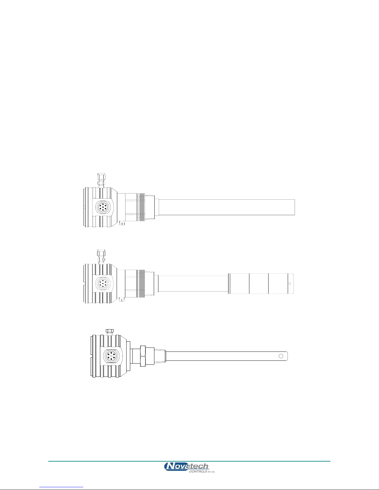
Model 1231 Heated Oxygen Probe
Model 1231 Heated Oxygen Probe with Filter
Model 1232 Unheated Oxygen Probe

August 2018 Technical Manual
1732 Oxygen Transmitter 11
3. DEVICE SPECIFICATIONS
3.1 Hardware Specifications
3.1.1 Transmitter Specifications
Number of Oxygen Probes:
1 or 2
Oxygen Range:
1 x 10-30 to 100%
Oxygen Accuracy:
±1% of actual measured oxygen value with a repeatability of ±0.5% of the
measured value
Thermocouple Types:
Type K and J
Temperature Accuracy:
±2C
Analog Outputs:
0-20mA or 4-20mA field selectable
Active Outputs
(WARNING: DO NOT LOOP POWER OUTPUTS. Use only passive receivers for commissioning and
testing. The use of loop powered receivers will damage the output)
Output Load:
1000 ohm max
Alarm Relays:
4
Alarm Relay Contacts:
2A 240VAC, 2A 30VDC
Reinforced insulation when used with mains voltage
(WARNING: Do not use both mains voltage and low voltage connections to adjacent alarm contacts)
Mains Voltage Supply:
100 to 240VAC 50/60 Hz
Reinforced insulation
Overvoltage:
Category II (IEC60364-4-443)
Power:
5 Watts for controller plus probe power
530W max., 25% duty cycle each probe on 240VAC
110W max., 100% duty cycle each probe on 110VAC
576W (2.4A) max
Environmental Rating:
Operating Temperature -25°C to 55°C
Relative Humidity 5% to 95% (non-condensing)
Altitude
2000m Maximum
Degree of Protection:
IP65
IP54 with internal reference air pump
Case Size:
315mm (12.4”) wide, 190mm (7.5”) high, 110mm (4.3”) deep
Case Weight:
3.3 Kg (7.3 lbs.)
WARNING: All signal level connections onto the transmitter must be treated as safety extra-low
voltage (SELV) as defined in the standard IEC61140. Double insulation must be used when
connecting these terminals to systems that might carry high voltage.

Technical Manual August 2018
12 1732 Oxygen Transmitter
3.1.2 Series 1230 Probes Specifications
MODEL
1231 Heated Probe
1232 Unheated Probe
Application
Insitu probe
Process gasses below 900°C
(1650°F)
Refer to note 1
Insitu probe
Process gasses above 700°C
(1290°F)
Temperature Range
0 to 900°C. Refer to note 2
(32 to 1650°F)
Stainless Steel: 700°C to 1000°C
(1290°F to 1830°F)
Alumina Ceramic: 700°C to 1400°C
(1290°F to 2550°F)
Length
Standard Lengths:
250 mm (10”)
350 mm (14”)
500 mm (20”)
750 mm (30”)
1000 mm (40”)
1500 mm (60”)
Standard Lengths:
500 mm (20”)
750 mm (30”)
1000 mm (40”)
Outer Sheath Material
316 Grade Stainless Steel standard
(Inconel with all Inconel wetted parts
optional)
316 Grade Stainless Steel standard
(Alumina Ceramic optional)
Process Connection
1½" BSP or NPT
¾” BSP or NPT
Electrical Connection
Weatherproof plug-in connector or optional screw terminals.
The plug connector can be supplied with the cable.
Cable
Order a specific length with the transmitter
Filter
Removable sintered titanium alloy
particulate filter
30-micron standard, optional 15-
micron available. Refer to note 2
n/a
Integrated Heater
Yes
No
Thermocouple
K, integral
None or R, integral as standard
(K, integral by special request).
Response Time
Typically < 4 seconds
Typically < 1 second
Head Temperature
-25 to 100°C (-15 to 210°F) with weatherproof connector
-25 to 150°C (-15 to 300°F) with screw terminals
Reference Gas
Ambient air, 50 to 150 cc/min
(3 to 9scim).
Pump can be supplied with the transmitter
Ref Air Connection
¼” NPT
Integral air-line in probe cable.
Barbed fitting to 3/16” ID PVC tube
Calibration Check Gas
Connection
⅛” NPT female
⅛” NPT female
Weight
2 kg (4.4 lb) plus 165 g (5.8 oz.) / 100
mm (4”) length
1 kg (2.2 lb) plus 100g (3.5oz) / 100
mm (4”) length
Notes:
1. Care must be taken to avoid contact with explosive or inflammable gases with 1231 heated probes
and 1234 oxygen sensors when hot. Novatech transmitters have built in safety protection.
2. Process gas temperature must be below 800C if the filters are fitted.
Please contact factory for corrosives other than sulphur or zinc. We can provide test materials to try in your
atmosphere.

August 2018 Technical Manual
1732 Oxygen Transmitter 13
3.1.3 Model 1234 Sampling Sensor Specifications
Application
Sampling Sensor
Used in RGS-17 Reference Gas Sensor
Range of Measurement
<1ppm to 100% Oxygen
Accuracy
±1%
Process Connection
¼” NPT female, inlet and outlet
Electrical Connection
Weatherproof plug-in connector or optional screw terminals.
The plug connector can be supplied with the cable.
Cable
Order a specific length with the transmitter
Heater
Yes
Sample Flow Rate
1 to 5 litres per minute (2 to 10scfh)
Differential Pressure
80 to 800 mmWG (3 to 30inWG)
Thermocouple
K, integral
Response Time
Typically <1 second
Reference Gas
n/a
Dimensions
300 x 125 x 85 mm (11.81” x 4.92” x 3.46”) HxWxD
Weight
2.2 kg (4.8 lb)
3.1.4 Probe Ordering Information
When ordering an oxygen probe please specify the following required options:
1. Probe to be heated or unheated
2. Probe insertion length (from process end of mounting thread to probe sensing tip)
3. Mounting thread for the process connection, BSP or NPT (for size of thread refer to specifications).
4. Lagging extension length, if required.
5. Electrical Connection Type.
6. Outer Sheath Material, if not specified will assume 316 stainless steel
7. For model 1231 heated probe state filter type if required. If not specified will assume no filters
8. For model 1232 unheated probe, state thermocouple type. If not specified will assume R-type.
For a list of options for the above requirements refer to the appropriate probe specification tables in the
previous section.

Technical Manual August 2018
14 1732 Oxygen Transmitter
3.2 Operational Specifications
Range of outputs:
Function
Minimum
Maximum
Linear Oxygen #1
0 to 99%
1 to 100%
Very low Oxygen #1
0 to 19,990ppm
10 to 20,000ppm
Linear Oxygen #2
0 to 99%
1 to 100%
Very low Oxygen #2
0 to 19,990ppm
10 to 20,000ppm
Average Oxygen
0 to 99%
1 to 100%
Logarithmic Oxygen
0.1 to 20%
Fixed range –refer to appendices
Reducing Oxygen
0 to 1x10-30%
0 to 100%
Oxygen Deficiency
-10 to 0%
-10 to 20%
Auxiliary TC Temperature
0 to 100°C
0 to 1600°C
Combustibles
0 to 19,000ppm
0 to 20,000ppm
Carbon dioxide
0 to 5%
0 to 100%
Probe #1 Sensor EMF
0 to 100mV
0 to 1500mV
Probe #2 Sensor EMF
0 to 100mV
0 to 1500mV
Burner Efficiency
0 to 20.0%
0 to 100.0%
No output
Disables the output
Range of local indication: 1.0 x 10⁻³⁰ to 100%
0.01 to 10,000ppm, automatically defaults to % range above 10,000ppm (1%)
Local display, lower line secondary display items:
Function
Range
Probe #1 temperature
Up to 1760°C (3200°F)
Probe #2 temperature
Up to 1760°C (3200°F)
Probe #1 EMF
-30 to 1350mV
Probe #2 EMF
-30 to 1350mV
Probe #1 sensor impedance
0 to 300k Ω
Probe #2 sensor impedance
0 to 300k Ω
Oxygen probe #2
1x10-30 to 100%
Average oxygen, probe #1 and probe #2
1x10-30 to 100%
Aux temperature
Up to 1760°C (3200°F)
Ambient temperature
-20° to 70°C (-5° to 125°F)
Ambient RH
5 to 95%
Carbon dioxide
0 to 2.0%
Combustibles
0 to 20,000ppm
Oxygen deficiency
-10.0 to 20.0%
Burner efficiency
0 to 100.0%
The oxygen deficiency output can be used in the same way as a combustibles analyser to signal the extent
of reducing conditions of combustion processes.
August 2018 Technical Manual
1732 Oxygen Transmitter 15
4. INSTALLATION AND COMMISSIONING
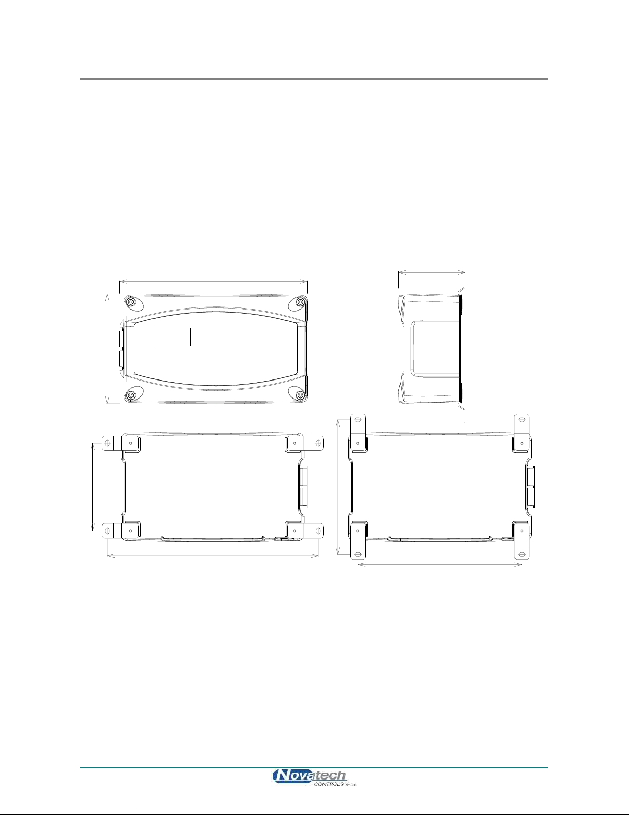
4.1 Mounting the Transmitter
Surface mount the transmitter case on to a flat surface or bracket, using the four mounting brackets
provided. The transmitter should never be mounted so that it is directly expose to the sun or rain. Always
leave at least 10cm of clearance around the four sides of the case.
Make sure the temperature of the case is below 55C, and that the radiated heat from furnaces and boilers is
kept to a minimum. There should be adequate ventilation to maintain ambient temperature.
Install the cables through cable glands. There are 4 holes cut in the base of the transmitter case; 2x 17mm
& 2x 21mm. Use a sharp knife to cut away the covering film for only the glands that are needed.
NOTE: ALWAYS LEAVE THE UNUSED GLAND HOLES SEALED.
Ensure that the electrical connection complies with the local electrical requirements. (see chapter 4.6
Electrical Connections)
Case Mounting Dimensions
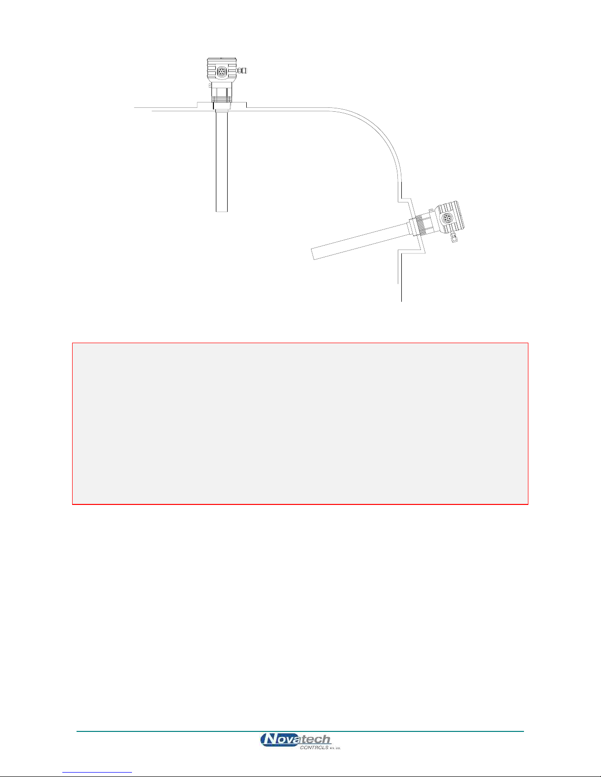
4.2 Installing a 1231 Oxygen Probe
Weld a BSP or NPT socket to the flue in a suitable position for flue gas sensing. For the correct size of
socket refer to probe data in Chapter 3.1.2 Series 1230 Probes Specifications. The closer to the source of
combustion the smaller will be sensing lag time, allowing better control.
The probe has a typical response time of less than four seconds, so most of the delay time is normally the
transit time of the gas from the point of combustion to the point of sensing.
Probes can be mounted at any angle. However, if the probe is to be mounted on a vertical duct wall, it is
better to angle the probe (approx. 15°) down to avoid process condensation inside the cold end of the probe.
If there are any particulates in the flue gas, a filter can be omitted by pointing the probe vertically downwards.
Otherwise the transmitter can be configured to automatically purge the filters, or they can be replaced
periodically.
315mm
185mm
355mm
145mm
275mm
225mm
110mm
Technical Manual August 2018
16 1732 Oxygen Transmitter
Oxygen Probe Mounting
CAUTION
It is important that there is no air in leakage upstream of the oxygen sensing point otherwise there will be a
high oxygen reading.
If the probe is to be installed on a bend in the flue, it is best located on the outer circumference of the bend to
avoid dead pockets of flue gas flow. While the standard 1231 probe with a ‘U’ length of 250 mm (10”) will
suit most low temperature flue applications, it is occasionally necessary to have a longer probe with the
sensing tip in the centre of the flue gas stream.
Although it is rare, occasionally a probe may sense oxygen vastly differently from the average reading in the
flue gas. If it occurs, then the probe should be moved, or a longer probe installed. This phenomenon is
normally caused by stratification of the flue gas.
Preferred mounting orientation
if there are particulates in the
flue gas and no filter is used
Furnace / Flue..
Probe may be mounted
horizontally, although angled
downwards at an angle of
approximately 15° will reduce
condensation

August 2018 Technical Manual
1732 Oxygen Transmitter 17
4.3 Installing a 1234 Oxygen Sensor
Mounting - Screw the 1234 Oxygen Sensor to a wall or similar surface with the piping connections at the
top.
1234 Sensor Mounting Dimensions
Sample Piping - Connect the gas sample piping to the “sample in” port. If the process, boiler, kiln or furnace
has a positive pressure, no suction will be required. If the sample is under a negative pressure, connect a
pump to the “inlet” port.The flow rate should be within the range of 1 to 5 litres/minute (2 to 10 scfh).
4.4 Installing the Auxiliary Thermocouple
Weld a 1/2-inch BSP mounting socket to the flue within about 300 mm (12”), and upstream of the oxygen
probe. The thermocouple should be of similar length to the oxygen probe to prevent flue temperature
distribution errors.
The thermocouple should be connected to terminals 7 & 8. These terminals will not be available for an
auxiliary thermocouple if a second probe has been installed.
N1595
Inlet ¼” Tube
Exhaust
Label
Cable Gland
Optional vent to
atmospherre
Optional return
to flue
Upward sloping
sample line 3/8”
stainless steel
Flue
Gas
Flowmeter
Sampling
Probe
1234
Sensor
Vent or return
to process
Dry
Process
Gas
1/4" Stainless Steel Tube
1234
Sensor

Technical Manual August 2018
18 1732 Oxygen Transmitter
4.5a Shield Connections
All external wiring to the 1732 transmitter should be shielded. Do not connect shields at the field end.
Simply clip off and insulate. There are two M4 earth screw terminals available in the 1732 transmitter. An
extra terminal strip may be required to connect all shields together. This should be supplied by the installer.
4.5b Earth connection (PE)
The PE (protective earth) input connection must be made to the earth stud on the right hand side of cabinet.
The PE input connection must be the first connection onto the earth stud and it must be secured by a
separate nut and spring washer. All other earth connections (bonding connections) can be made on either of
the two earth studs in the base of the cabinet.
The transmitter MUST be securely earthed.
Assembly of the PE and bonding connections on the earth stud
Incoming
PE wire
Other bonding
earth wires
Right hand
earth stud
Other manuals for 1732
1
Table of contents
Other Novatech Transmitter manuals


Popular Transmitter manuals by other brands


ABB
ABB KSONIK MICRO Operation & instruction manual

Extron electronics
Extron electronics DTP3 T 202 user guide

NOSHOK
NOSHOK KING-GAGE 5900 OPERATION & CALIBRATION MANUAL

American Time
American Time SiteSync IQ Quick start installation guide

Lectrosonics
Lectrosonics UM450V instruction manual

Dwyer Instruments
Dwyer Instruments IEF Series Operating instruction


