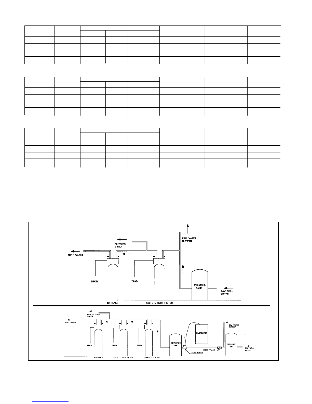
Novatek NACF75 User manual

Novaclean Automatic
Water Filters
Operation Manual
ACF Activated Carbon Filter, MMF Multimedia Filter, NF Neutralizing Filter
Page 5 of this manual contains important maintenance procedures required for the continued
proper operation of this unit. hese MUS be performed regularly for your guarantee to
remain valid.
51876 Rev. 11/08

1
Typical Installations
Novaclean MMF - Specifications
Model Media Flow Rates USGPM Installation Space Fibe glass Tank Shipping
Desc iption Cu Ft Se vice Peak Backwash Inches - W x D x H Size - Inches Weight - Lbs
NMMF75 .75 4 5 4 10 x 10 x 57 8 x 47 95
NMMF10 1.0 5 7 5 11 x 11 x 58 9 x 48 145
NMMF15 1.5 7 10 7 12 x 12 x 64 10 x 54 213
NMMF20 2.0 10 12 10 14 x 14 x 62 12 x 52 265
Novaclean ACF - Specifications
Model Ca bon Flow Rates USGPM Installation Space Fibe glass Tank Shipping
Desc iption Cu Ft Se vice Peak Backwash Inches - W x D x H Size - Inches Weight - Lbs
NACF75 .75 4 5 3.5 10 x 10 x 57 8 x 47 45
NACF10 1.0 5 7 5 12 x 12 x 57 10 x 47 65
NACF15 1.5 7 10 7 14 x 14 x 62 12 x 52 93
NACF20 2.0 10 12 10 16 x 16 x 60 14 x 50 105
Novaclean NF - Specifications
Model Media Flow Rates USGPM Installation Space Fibe glass Tank Shipping
Desc iption Cu Ft Se vice Peak Backwash Inches - W x D x H Size - Inches Weight - Lbs
NNF75 .75 2 3.5 3.5 10 x 10 x 57 8 x 47 75
NNF10 1.0 3 5 4 11 x 11 x 58 9 x 48 115
NNF15 1.5 5 8 5 12 x 12 x 64 10 x 54 165
NNF20 2.0 6 10 7 14 x 14 x 62 12 x 52 215
• Peak flow rates intended for intermittent use only (10 minutes or less) and are for
residential applications only. Do not use peak flow rates for commercial
applications.
• At the stated flow rates, the pressure drop through these de ices will not exceed 15
psig.
• For satisfactory operation, the pumping rate of the well system must equal or
exceed indicated backwash flow rate.
• Maximum Water Temperature = 110oF (43oC)
• Maximum Operating Pressure = 100 PSIG (689 kPa)
• Pipe Size = 3/4”
• Voltage = 110V Standard
• The manufacturer reser es the right to make product impro ements which may
de iate from the specifications and descriptions stated herein, without obligation to
change pre iously manufactured products or to note the change.
NOTE: A neut alizing filte is the fi st unit installed in a wate system afte the outdoo aw wate lines (*) when pH co ection is
equi ed.

2
Installation Instructions
CAUTION:
If the g ound f om the elect ical panel o b eake
box to the wate mete o unde g ound coppe
pipe is tied to the coppe wate lines and these
lines a e cut du ing installation of the No yl
bypass valve and/o poly pipe, an app oved
g ounding st ap must be used between the two
lines that have been cut in o de to maintain
continuity. The length of the g ounding st ap will
depend upon the numbe of units being installed
and/o the amount of coppe pipe being eplaced
with poly. See Figu e 1.
In all cases whe e metal pipe was o iginally used
and is late inte upted by poly pipe o the No yl
bypass valve, as in Figu e 1 o by physical
sepa ation as in Figu e 2, to maintain p ope
metallic pipe bonding, an app oved g ound clamp
c/w not less than #6 coppe conducto must be
used fo continuity.
Check you local elect ical code fo the co ect
clamp and cable size.
NOTE: This time ’s p og ams will be out of sync if
you tu n the knob too fa o do not allow the d ive
moto to stop completely befo e continuing to the
next step. If this happens while doing any
p ocedu e, otate the knob clockwise until the
white dot lines up with the time of day a ow and
the unit will etu n to the se vice position. You can
then sta t again.
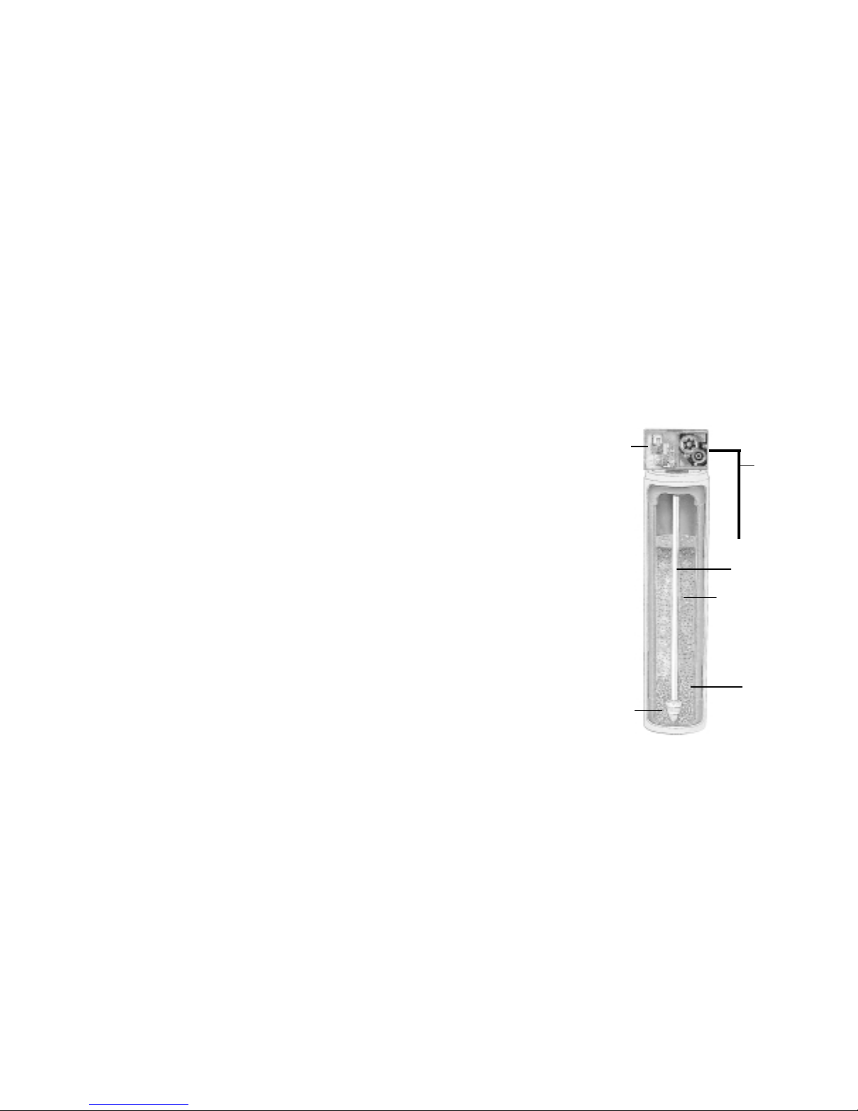
1. Place filte on a flat su face in desi ed location, nea a d ain and 115 volt AC outlet. Subjecting you filte to f eezing o to
wate tempe atu es above 120°F (49°C) will void the wa anty. Remove the valve f om the ca ton. Be su e the dist ibuto
tube is in place. Ca efully position the valve ove it and tu n secu ely on to the fibe glass tank.
Note: All multi media and some la ge units a e supplied with the media sepa ate. Please efe to page 5 Installations &
Replacement of Filte Media Pak.
2. Attach the installation kit o bypass to the cont ol valve. Make inlet and outlet wate connections to meet applicable
plumbing codes. A 3/4” inlet line is ecommended. When sweat fittings a e used, solde the adapte s fo the inlet and outlet
to the coppe pipe fi st. This p ocedu e is necessa y because the cont ols must not be subjected to tempe atu es above
160°F (71°C). Then, using teflon tape, sc ew the adapte s fo the inlet, outlet and d ain into the valve. CAUTION: do not
use pipe th ead compound as it may attack the mate ials in the valve body.
3. On the d ain, use 1/2” hose ba b supplied and full 1/2” hose (not supplied) fo the d ain line and make the sho test un to a
suitable d ain. The d ain line must be secu ed in position at the end which discha ges into the d ain so it cannot be
inadve tently moved f om the d ain.
4. Loosen the two sc ews on the time cove to emove it f om the time .
5. Automatic wate filte s a e supplied f om the facto y in the backwash position, eady fo sta t up. Tu n on the wate supply
to the unit. Open the supply line slowly and allow the ai to escape f om the filte befo e tu ning the supply wate on all the
way. Allow the unit to backwash until all the ai and media fines a e no longe showing at the d ain. This may take up to 15
minutes so you need to unplug the time until you a e eady to continue.
6. Plug the time in, set the time and f equency of egene ation following inst uction on page 4. Allow the unit to complete the
cycle on its own f om this point.
7. Make su e the bypass valve is in the se vice position.
Installation and Start-up Procedure
ALL GOVERN ENT CODES GOVERNING INSTALLATIONS OF THESE DEVICES UST BE OBSERVED.
Elect ical Panel
G ound St ap
Poly Pipe
G ound F om Panel Poly Pipe
Filte
c/w Plastic Bypass
Coppe Pipe
Wate Mete
Outside Wate Line Fo Outside & 3 d Tap Comes F om Mete
Filte ed Wate Line in Home
Unfilte ed Wate Bypass
Loop Cut & Capped G ound St ap Requi ed Because
of B eak in Continuity
Figu e 2
Figu e 1

3
Operating Instructions
How Your Automatic Filter Works
Raw wate ente s you home th ough the main supply line, ente s you filte , and passes downwa d th ough the media bed.
Impu ities such as tu bidity and sediment (MMF) and o ganics (ACF) a e emoved f om the wate . The filte ed wate then flows
up and into you household wate lines.
The neut alizing filte (NF) is designed to aise the pH of you wate to eliminate co osive cha acte istics.
EXA PLE: A pH of 5.5 can be aised to 7.0 which is neut al. When the wate is neut alized it is then possible to emove the
i on with the addition of an i on filte .
Water Pressure
You wate filte is designed to ope ate unde no mal wate p essu es f om 20 psi to 125 psi.
Regeneration and Automatic Bypass
Wate filte s a e facto y set to egene ate at 1:00 a.m. du ing a pe iod of little o no wate use. The egene ation cycle lasts
app oximately 15 minutes, afte which filte ed wate se vice is esto ed. While egene ation is taking place, “ aw wate ”
automatically bypasses the filte if equi ed. If possible, avoid using wate du ing egene ation to p event unfilte ed wate
ente ing you household plumbing system. Note: When mo e than one filte is being used, egene ation should be stagge ed by
15 minute inte vals f om 1 a.m.
anual Bypass (Figu e 3A)
In case of an eme gency, you can isolate you wate filte f om the
wate supply using the bypass valve located at the back of the cont ol.
In no mal ope ation the bypass is open with the on/off knobs in line with
the inlet and outlet pipes. To isolate the filte , simply otate the knobs
clockwise (as indicated by the wo d BYPASS and a ow) until they lock.
You can use you wate elated fixtu es and appliances as the wate
supply is bypassing the filte . Howeve , the wate you use will be
unfilte ed.
To esume filte ed wate se vice, open the bypass valve by otating the
knobs counte -clockwise.
Stainless Steel Bypass (Figu e 3B)
In no mal ope ation the bypass leve is aligned with the inlet/outlet with
the pointe on SERVICE. To isolate the filte , otate leve counte
clockwise until it stops and pointe indicates unit is in bypass.
You can use you wate elated fixtu es and appliances as the wate
supply is bypassing the filte . Howeve , the wate you use will be
unfilte ed.
To esume filte ed wate se vice, open the bypass valve by eve sing
the otation of the leve .
New Sounds
You will notice new sounds, such as the hum of the time , as you filte
ope ates. Du ing egene ation, it will not be uncommon to hea wate
unning to the d ain.
INLET
OUTLET
OUTLET
INLET
Figu e 3B
Figu e 3A

4
Programming Backwash Controls
Setting The 24-Hour Timer
P ess and hold the ed button in to disengage the d ive gea . Tu n
the la ge dial until the actual time of day is opposite the time of
day pointe . Release the ed button to e-engage the d ive gea .
Determining The Backwash Frequency
The following table can be used to help dete mine the f equency of
egene ation. Use this table as a guide – individual ci cumstances
will equi e mo e o less f equent egene ations.
To set a neut alizing filte follow the table unde mild conditions.
NOTE: Add one pe son if you have a dishwashe .
Setting The Backwash Frequency
The filte cont ol featu es a skippe wheel with twelve
numbe ed tabs and t ip finge s. Each ep esents one
day of a twelve day schedule. By adjusting the
skippe wheel tabs, the cont ol can be p og ammed to
backwash eve y second, thi d, fou th, sixth o twelfth
day, acco ding to you equi ements.
The cont ol is shipped with all the skippe wheel tabs
pushed outwa ds. You must push the tabs in towa d
the cente of the wheel ( et acting the t ip finge ) fo
each day that backwashing is not equi ed.
Rotate the skippe wheel until numbe “1” is at the pointe , leave this tab out. Moving clockwise ound the skippe wheel adjust
the emaining tabs using the following table as a guide.
anual Regeneration
Tu n the manual egene ation knob clockwise. This slight movement of the manual egene ation knob engages the
p og am wheel and sta ts the egene ation p ocess. The back cente knob will make one evolution in app oximately
th ee hou s and stop in the position shown in the d awing. Actual backwash time is 14 minutes. In any event, t eated
wate may be d awn afte inse wate stops flowing f om the filte ’s d ain line.
Skippe Wheel Tab Settings
123456789101112
1 Out In In In In In In In In In In In
2 Out In In In In In In In In In In In
3 Out In In In Out In In In Out In In In
4 Out In In Out In In Out In In Out In In
6 Out In Out In Out In Out In Out In Out In
No. of backwashes
equi ed in
12 days
MMF SEDIMENT
FILTERS TURBIDITY MILD AVERAGE EXTREME
ACF TASTE
FILTERS ODOR MILD AVERAGE EXTREME
No. of Pe sons Calenda Clock Regene ation F equency - No. of Tabs Pushed outwa ds
2 1 111122 22 23 3 3 333
3 1 122333 33 34 4 4 444
4 1 222333 44 46 6 6 666
5 2 233444 46 66 612121212
6 2 233444 66 661212121212
7 2 334466 61212121212121212
8 2 334666 61212121212121212
9 3 3446612121212121212121212
10 3 44661212121212121212121212

5
aintenance Instructions
Maintenance of you new wate filte equi es ve y little time o effo t but it is essential. Regula maintenance will ensu e many
yea s of efficient and t ouble f ee ope ation.
Care of All Water Filters
To etain the att active appea ance of you new wate filte , clean occasionally with a mild soap solution. Do not use ab asive
cleane s, ammonia o solvents. Neve subject you filte to f eezing o to wate tempe atu es above 120°F.
Replacing edia Bed
NF - the media bed in a neut alizing filte is slowly dissolved and has to be eplaced. The f equency of eplacement va ies,
depending on wate quality – consult you deale to dete mine the expected life of you media bed.
ACF - unde no mal ope ating conditions the effective life of the filte media is app oximately one to th ee yea s depending on
the wate quality, afte which, taste and odo p oblems may etu n. When this happens contact you deale fo a eplacement
media bed.
F - unde no mal ope ating conditions, the media should neve need to be eplaced. If you expe ience p essu e loss and
cannot co ect it with a manual egene ation, you media bed may need eplacing – contact you deale .
Installation & Replacement of Filter edia Pak
Check to ensu e all media pa ts a e eceived.
The fi st step in eplacing the media bed is to shut off the wate supply to the filte . Then
place the unit into the backwash position to elease any p essu e in the lines. At this point,
you must disconnect the plumbing f om the inlet and outlet. Then unsc ew the cont ol
valve (Item A) f om the fibe glass tank. Once this has been done, emove the dist ibuto
tube (Item B). Then you can emove the filte media and two types of g avel f om the tank.
The quickest way to do this is by simply tipping the tank upside down into a la ge d um o
pail. The tank must be insed out completely and have no media o g avel left in it at all.
Loading the edia-Pak
Place the dist ibuto tube (Item B) back down the cente of the tank. The top of this tube
should be plugged with a ag o co k to p event media f om ente ing. Pou the bag of coa se
g avel (Item E) into the tank, then pou the bag of fine g avel (Item D) into the tank.
It is important that the distributor tube is not moved or pulled out as it would not be
possible to put it down to the bottom of the tank once gravel or media are in the tank.
Finally pou the la ge bag(s) of media into the tank.
Fo multi-media units only. These units have to be loaded in the following o de :
1. Coa se g avel (1/2 x 1/4) 4. Fine ga net (30 x 40)
2. Fine g avel (1/8 x 1/16) 5. Fine filte sand (.45 x .55)
3. Coa se ga net (8 x 12) 6. Anth afilt
Once this is done, the ag o co k should be emoved f om the dist ibuto tube. Clean off the top of the tank. Finally place the
cont ol valve on the tank and onto the dist ibuto tube. Tighten the cont ol valve onto the tank. Connect o econnect the inlet
and outlets and d ain. The cont ol valve should be in the backwash position. Slowly open the inlet valve wate supply and
slowly fill the filte tank until wate appea s at the open d ain line (Item F). Retu n the cont ol to the se vice position and shut the
inlet off fo app oximately one hou to allow the media to soak in the wate .
Afte one hou , tu n inlet wate on slowly and place the cont ol into the backwash position and plug the unit’s elect ical co d into
a constant powe sou ce. Let the unit continue th ough its egene ation cycle automatically.
The egene ation is necessa y so all media fines a e backwashed down the d ain to ensu e clean filte ed wate . Afte this
media has been eplaced, it may be necessa y to eset the p esent time of day on the cont ol valve time as it will have been
unplugged fo some time.
Control
Valve
Drain
Line
Distributor
Tube
Coarse
Gravel
Fine
Gravel
edia

Trouble Shooting Guide
PROBLE CAUSE CORRECTION
1. Filte bleeds taste and odo o Bypass valve is open Close bypass valve.
sediment
Elect ical se vice to unit has been Assu e pe manent elect ical se vice (check fuse,
inte upted plug o switch).
Defective o st ipped media bed Replace media.
Quality of wate has wo sened Have wate sample analyzed to dete mine any
change.
Filte capacity too small Replace with la ge unit o add anothe filte .
Filte not backwashing enough Be su e cont ol is not clogged o d ain line
est icted. Be su e wate p essu e has not
d opped and that pump has sufficient capacity.
Excessive wate usage Inc ease f equency of egene ation. Make su e
the e a e no leaks in toilets o sinks.
Tabs on skippe wheel not out Push as many tabs to the outside of the skippe
wheel as necessa y to p ovide adequate f equency
of egene ation.
2. Filte fails to egene ate Elect ical se vice to unit has been Assu e pe manent elect ical se vice (check fuse,
inte upted plug o switch).
Time is defective Replace time .
Powe failu e Reset time of day.
B oken cogs on the 24 hou gea Replace 24 hou gea .
Time moto does not un Replace defective moto .
3. Filte egene ates eve y day Faulty gea t ain Check the mechanical linkage on the time cont ol
to eliminate possible binding in the gea t ain.
4. Loss of wate p essu e I on o tu bidity build-up in filte Clean cont ol and t eat bed with P o-Rust Out.
Inc ease f equency of egene ation.
Filte not egene ating often enough Inc ease f equency of egene ation.
Not enough wate volume o p essu e Co ect wate supply p oblem.
to backwash p ope ly
5. Loss of media th ough d ain line Ai in wate system Assu e that well system has p ope ai eliminato
cont ol. Check fo d y well condition.
Backwash ate too fast Check d ain flow cont ol fo p ope flow ate.
6. D ain flows continuously Fo eign mate ial in cont ol Remove piston assembly and inspect bo e,
emove fo eign mate ial and check cont ol in
va ious egene ation positions.
Time moto stopped o jammed Replace time moto .
6

Guarantee
Novatek gua antees that you new wate conditione is built of quality mate ial and wo kmanship. When
p ope ly installed and maintained, it will give yea s of t ouble f ee se vice.
Seven Year Complete Parts Guarantee:
Novatek will eplace any pa t which fails within 84 months f om date of manufactu e, as indicated by the se ial
numbe p ovided the failu e is due to a defect in mate ial o wo kmanship. The only exception shall be when
p oof of pu chase o installation is p ovided and then the wa anty pe iod shall be f om the date the eof.
Lifetime Guarantee on ineral Tanks and Brine Tanks:
Novatek will p ovide a eplacement mine al tank o b ine tank to any o iginal equipment pu chase in
possession of a tank that fails within his/he lifetime, p ovided that the wate conditione is at all times ope ated
in acco dance with specifications and not subject to f eezing.
General Provisions:
Novatek assumes no esponsibility fo consequential damage, labo o expense incu ed as a esult of a defect
o fo failu e to meet the te ms of these gua antees because of ci cumstances beyond its cont ol.
WATERGROUP INC. WATERGROUP CO PANIES INC.
FRIDLEY, MN REGINA, SK • CAMBRIDGE, ON
1-800-354-7867 1-877-288-9888
www.watergroup.com
This manual suits for next models
11
Table of contents