NOXAS ID-O-Matic User manual

ID-O-Matic Manual 11/7/2007 Page 1 of 6
NØXAS ID-O-Matic
ID Timer / Annunciator
The ID-O-Matic kit uses a microprocessor based, single chip ID timer/annunciator intended for Amateur
Radio and other applications. Several modes of operation make it suitable for use in the shack or as an
automatic Morse code ID for beacons, repeaters and “fox hunt” transmitters. The ID-O-Matic chip is a
compact, single 18-pin package ideal for standalone use or integration into transmitter or transceiver. These
instructions detail the assembly and use of the ID-O-Matic kit.
ID-O-Matic Features
(Firmware version 2.8)
•Supply voltage up to 24V with on-board
regulator
•Low parts count, easy to assemble
•Serial interface for setup from PC or
terminal
•Dual color LED for green/yellow/red
indicator
•Reminder mode for shack use
•Delays from 1 second to over 9 hours may
be set
•All memory and parameter settings retained
with power off
•Auto ID mode with repeater inputs
•Morse code speed adjustable from 5 to 60
WPM
•INHIBIT input to delay ID
•START input to prevent repeater
“beaconing” on quiet channel
•Repeater beacon timer to announce at
regular intervals when desired
•Separate normal and beacon ID messages
can be used, up to 64 characters each
•Optional, variable length courtesy beep for
repeater mode use
•Independent audio frequencies for Morse ID
and courtesy beep
•Adjustable PTT hang time
•PTT time-out timer
•Audio (MCW), CW and PTT outputs
•CW and PTT outputs drive MOSFETs for
direct connection to many rigs
•AR, BT, SK prosigns and new @ character
supported

ID-O-Matic Manual 11/7/2007 Page 2 of 6
Kit Construction:
Keep all semiconductor parts in the anti-static foam or tube until you are ready to use them. Always use good static prevention
practices when working with static sensitive parts. This means you should wear a grounding strap when possible, or work on a
static-dissipative work surface. Use a grounded tip soldering iron. When soldering small parts it is a good idea to use a small,
pencil-type soldering iron of no more than 25 Watts or so, or a temperature controlled soldering station. Use pliers, clamps or
alligator clips as heat sinks to prevent heat damage to parts while soldering. If you are not fairly experienced with soldering
small parts, you may want to practice on some scrap parts first or get some help.
Work in an area with good lighting. You may want to use a magnifying lens to do some of the small soldering required. Insert
each component from the top of the board (the side with the white silkscreen lettering), in the order shown in the instructions
below. As each component is installed, solder the leads and trim off excess leads with a small pair of side cutters.
1. Install the 10K Ohm resistor (brown-black-orange) in the location marked R1.
2. Install the 470 Ohm resistor (yellow-violet-brown) in the location marked R2.
3. Install the 1K Ohm resistor (brown-black-red) in the location marked R3.
4. Install a 2.2K Ohm (red-red-red) resistor in location R4.
5. Install a 2.2K Ohm (red-red-red) resistor in location R5.
6. Install the .1 F capacitor (marked 104) in location C1.
7. Install the .33 uF capacitor (marked 334) in location C2.
8. Install 2N7000 MOSFET transistors in locations Q1, Q2, Q3 and Q4. Make sure the transistors are oriented as
shown on the board.
9. Install the 18-pin IC socket in location U1. M make sure notch in socket is positioned to match the board outline.
Do not install the chip yet.
10. Install the 78L05 voltage regulator in location VR1. Check for proper orientation with outline on board. NOTE:
If you wish to use battery power or a 5V DC power supply, do not install VR1. Instead, solder a jumper wire between
pins 1 & 3 of the position marked VR1. This will bypass the voltage regulator option.
11. Carefully install the small 4 MHz cylindrical crystal in location X1. NOTE: This part is easy to damage with
excess heat while soldering. Be extra careful!
12. Install the DB-9 connector in location J1.
13. Mount the Dual-color LED in the position indicated. Mount the LED so the shortest lead (red cathode) and flat
side of the LED base is toward the bottom of the board, closest to the board edge. You can mount the LED remotely
using any convenient length of wire.
Powering the ID-O-Matic:
Power can be supplied by battery or a DC power source up to 24V if you have installed VR1 and C2. If you wish to use a low
voltage source (from 3.5 to 5 V DC) you can omit VR1 and install a wire jumper between pins 1 and 3 of the VR1 position on
the circuit board. Connect the power input to the two points on the circuit board marked PWR; polarity is marked by ‘-‘ and
‘+’ signs below the pads. Warning: There is no diode to protect against reversed power leads – double check your
connections!! You can use any suitably sized SPST power switch to fit your application. If you opt for low voltage and
jumper out VR1, any smooth, regulated DC voltage from 3 to 5.25 V should work fine. Three AA alkaline cells should last
quite a while for shack use as a simple ID reminder. If you plan to build your ID-O-Matic into a rig or a repeater controller,

ID-O-Matic Manual 11/7/2007 Page 3 of 6
don't worry about battery backup; all memory and parameter settings are retained in non-volatile EEPROM memory and will
be automatically recalled when power is applied.
Check the power supply voltage at pins 5 (GROUND) and 14 (POWER) on the 18-pin IC socket. Once you have verified that
there is a safe voltage between 2.5 and 5.25 Volts, remove power and install the ID-O-Matic chip in the socket. Make sure to
orient the chip properly, with the Pin 1 dot toward the notch in the silkscreened outline on the PCB.
Off-Board Connections
You will probably want to install a RESET switch, speaker, etc. Pads are provided to connect a SPST normally open
pushbutton switch to reset the timer. There are also two pads marked SPK for audio Morse code output to a speaker or to
connect to your equipment.
A series of six pads (marked JP1) are provided along the edge of the board opposite the serial connector. These connections
may be left unconnected, or can be used as follows:
Pad Function
JP1-1 TEST input; ground this to hear the CW ID message.
JP1-2 INHIBIT input; active low logic level input.
JP1-3 START input; active low logic level input for COR or squelch signal.
JP1-4 PTT output; open-drain MOSFET, 60 V 200 mA max.
JP1-5 CW output; open-drain MOSFET, 60 V 200 mA max.
JP1-6 Ground
Operation
Simple timer mode:
For shack use as a simple ID reminder, simply turn the ID-O-Matic on. The LED should show green for nine minutes, then
turn yellow. At nine minutes thirty seconds, the LED will begin to blink yellow and red. After ten minutes the LED will turn
solid red and the ID-O-Matic will start to beep at you to remind you to ID. The open-drain PTT output can be used to drive an
external indicator such as a lamp or LED. Push the RESET button to start a new cycle any time you ID.
Auto ID mode:
Similar to the simple timer mode, this will send a Morse ID at regular intervals. The INHIBIT input can be used to delay the
ID if needed. Note that two Morse outputs are provided; there is CW output that is used for on-off keyed devices (CW
transmitters, etc) and an audio output. PTT is also active in Auto ID mode. The ID message will be sent every time the ID
timer reaches zero, and the timer will automatically reset and begin counting again. This can be useful for “fox” transmitters,
beacons, etc.
Repeater mode:
In this mode of operation, the START input is used to indicate that the transmitter has been keyed. It is normally connected to
either a receiver COR/COS output, or to the PTT line normally connected to the transmitter. When the START input first goes
low (active), the ID timer is loaded with your specified ID interval and starts counting down. At this time the LED will begin
flashing green. When the ID timer reaches 60 seconds, the LED goes to solid yellow. At 30 seconds, the LED begins
alternating red and yellow until the timer expires. At that point the LED goes solid red and the ID message is sent. The
yellow and blink times are configurable using the setup menu.
If the interval since the last ID message has been longer than the ID interval – for instance, if your ID interval is set to 10
minutes and the repeater has been idle for more than 10 minutes since the last ID -- an ID will be sent 10 seconds after the first
time START goes active. The ID timer is then reset with the normal ID interval. During this phase, a “polite” ID is used; the
ID message will not be sent until START is released OR the normal ID interval is reached.
The INHIBIT Line can be used to hold off the ID until the repeater is not busy. As long as INHIBIT is held low, the ID
message or beacon message will not be sent. As soon as it is released, any pending message will be sent.

ID-O-Matic Manual 11/7/2007 Page 4 of 6
The PTT output is always active when the ID or beacon message is being sent. It is also active:
•If PTT hang time is set (not zero), the entire time START is active plus the length of the PTT hang time setting;
•If a courtesy beep is set, the entire time START is active plus half a second and the length of the courtesy beep;
•If both are set, the entire time START is active, plus the courtesy beep and hang time delays.
Setup
For beacon, foxhunt or repeater use, connect your ID-O-Matic to a PC or other serial terminal device using a straight-through 9
pin serial cable. If you have built your own custom device using the ID-O-Matic chip, you can use the kit schematic as a guide
to build your own interface level converter. If using a PC you can use the HyperTerminal program provided with Windows, or
just about any other serial communications program such as Procomm. Set your communication parameters for 9600 baud,
eight bits, no parity, one or two stop bits and no handshake. As a quick check to see if your serial port and communication
software is set up correctly, connect a serial cable to the computer but not to the ID-O-Matic. Connect pins 2 & 3 together at
the end of your serial cable. Anything you type should be echoed back to your computer.
Connect the ID-O-Matic and turn the power on. You should see the version number printed on your screen. Tap the ENTER
key twice to enter the setup menu. You will be prompted for several bits of information. In each case you can hit RETURN to
keep the current setting, which will be displayed in parenthesis after the prompt.
•ID Time: Enter the delay time, in seconds. This will be the time between ID reminders or Morse announcements.
•Yellow time: Enter the number of seconds from zero at which you want the LED to turn solid yellow. Setting this
value to zero disables turning the LED yellow.
•Blink time: Enter the number of seconds from zero at which you want the LED to begin blinking red/yellow. Setting
this value to zero disables red/yellow blinking.
•ID msg: Enter up to 64 characters for your desired Morse code ID. Common punctuation and prosigns are supported:
oType a dash (–) for BT
oType a semicolon (;) for AR
oType a greater-than (>) for SK
o@ will be sent as the new @ sign character (.--.-.)
oComma, period, slash and question mark signs are sent as typed
oTo send a steady tone or CW carrier for a specified length of time (such as for a propagation beacon), type
:nnn:where nnn is the number of seconds from 1 to 255.
oLess-than (<) and other characters will be ignored.
oSpaces, including trailing spaces, will be sent. Note that entering a space as the first character of a
message will delete the message.
•Beacon msg: Similar to the ID message, this message will be sent if the beacon time is set. If the beacon time is set
and this message is empty, the ID message will be sent at beacon time instead.
•Auto CW ID: Type Y to use the Morse code ID, or N for a simple beeping ID reminder.
•CW Speed: Enter the desired Morse code speed in words per minute. This will also affect the rate of beeping if Auto
CW ID is off.
•ID Audio Tone: Enter the desired Morse ID audio frequency in Hz between 250 3500. The ID-O-Matic will set a
speed as close as possible to your selection. The value displayed will be the actual calculated frequency.
•Repeater mode?: Type Y if you intend to use the START input. Type N if you do NOT plan to use the START
input, even if it will be used in a repeater.
•Courtesy beep tone: This prompt will only appear if you answered “Y” to Repeater mode. With the courtesy beep
tone set to an audio frequency (in Hz) between 250 and 3500, the ID-O-Matic will send a short beep about 500
milliseconds after the START input goes inactive (high). Set this to zero to disable the courtesy beep.
•Courtesy beep mult: If you have selected Repeater mode, this allows you to “stretch” the length of the courtesy beep.
Enter a number indicating the length of the desired courtesy beep as a multiple of “dit” times – this means the courtesy
beep length is determined by the current Morse code speed selected.
•Beacon time: This prompt will only appear if you answered “Y” to Repeater mode. Setting this to other than zero
will cause the ID-O-Matic to send a Morse message at regular intervals if nothing is seen on the START input while
in repeater mode. This can be set to 3600 to announce the repeater every hour, for example, if the repeater is idle.
ID-O-Matic Manual 11/7/2007 Page 5 of 6
Enter the number of seconds you wish to have between beacons, up to 65535. The beacon message is used if it is set,
otherwise the ID message will be used. Set this to zero to disable beaconing.
•PTT hang time: The PTT hang time setting can be used to control the behavior of the PTT output. The value is
specified in seconds. While in repeater mode with PTT hang time set to 0, the PTT output will be active only when
the ID or courtesy beep is being sent, plus a half-second delay. With PTT hang time set to 1 or more, PTT will be
active as soon as the START in put goes low and will remain active for the specified number of seconds after the
START input goes high and any ID or courtesy beep is finished.
•PTT Max: This setting will specify the maximum number of seconds the ID-O-Matic will allow PTT to be active. If
the START input is active for longer then this setting, the ID-O-Matic will send “TOT” (for “Time-Out Timer”), then
send the ID message and disable PTT until the START input is inactive.
Status LED colors and what they mean
Green (solid) Timer is operating; timer is more than 60 seconds from expiring.
Green (blinking) In repeater mode, START input has been seen and ID timer is running.
Yellow Timer is within 60 seconds (or YELLOW time) of expiring.
Yellow/Red Blinking Timer is within 30 seconds (or BLINK time) of expiring
Red Timer has expired. In repeater mode, ID is being transmitted.
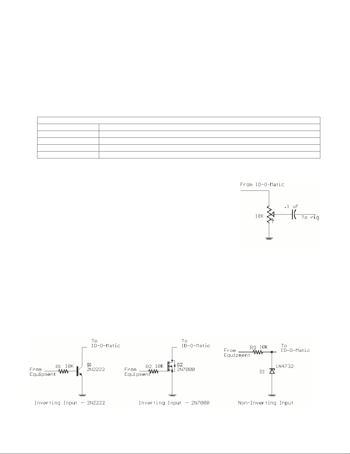
Morse code audio:
A square wave audio signal is provided on Pin 9. You can drive small loads such as
many piezo speakers directly from the pin or through a capacitor, or use a small audio
amp and filter if you wish. Some possibilities for sidetone include directly driving a
piezo speaker or using a small transistor amplifier. More elaborate solutions might
include an audio amplifier such as an LM386 with filtering to "round off" the square
wave to produce a more comfortable tone. If you are feeding the audio to a repeater,
crossband rig or other device you’ll probably want to use a simple circuit to block DC
voltage and allow you to adjust the audio level. One example of such a circuit is shown
at right.
Connecting to your equipment:
The PTT and CW outputs are open-drain MOSFET outputs, and can be directly connected to inputs that do not exceed 60V or
20 mA at any time. They can be used to drive low current relays if needed. If you intend to use the ID-O-Matic with
equipment requiring grid-block or cathode keying or any other application that will exceed 60 Volts or 200 mA, you will need
to add a grid-block keying adapter such as the Universal Keying Adapter 2 or some other suitable output arrangement.
The INHIBIT, START and TEST inputs may be left floating (unconnected) if not used. These inputs are active-low logic
signals, meaning they are active when driven below 1V. Be careful not to exceed 5V input on either of these signals. If your
equipment uses active high outputs, you can use a simple 1-transistor inverter. If your equipment uses voltages exceeding 5V,
you can use a simple Zener diode circuit to reduce the voltage to a compatible level. Some examples of interface circuits are
shown below:

ID-O-Matic Manual 11/7/2007 Page 6 of 6
A kit is available to make connecting your ID-O-Matic to other equipment much easier. The Connection Kit provides inverting
and non-inverting inputs, voltage limiting, an audio amp/mixer/filter, and optional PTT for many handheld transceivers. It is
designed to plug directly onto the ID-O-Matic board “piggy-back” style. You can check out the Connection Kit at
www.HamGadgets.com.
Support:
Should you need support, have questions, have feature requests or bug/problem reports, please feel free to contact me via email
at [email protected]rg or [email protected]. I will make every effort to respond as quickly as possible.
Warranty:
All parts are tested and are guaranteed against defects for 90 days from date of purchase. This warranty does not cover damage
due to incorrect assembly, improper soldering or wiring, overvoltage, static damage or other misuse or abuse. If you have
problems, please contact me via email to arrange for an exchange or replacement part. If you accidentally damage a part, don’t
panic – just contact me, replacements are not expensive.
Schematic of ID-O-Matic Kit:
Table of contents
Other NOXAS Control Unit manuals


Popular Control Unit manuals by other brands


WDT
WDT Granudos 10 Touch Operating and installation instructions

Parker
Parker DINCon II Installation, operating, & maintenance instructions

Aventics
Aventics CO1 Assembly and operating instructions

PLARAD
PLARAD X32 Series Translation of original operating manual

Quectel
Quectel Smart EVB G5 user guide

Tridonic
Tridonic basicDIM Wireless installation instructions