Noyes TURBOTEST 400 User manual

TURBOTEST 400
Fiber Optic Certification Test Set
User’s Guide
© 2002, AFL Telecommunications, all rights reserved. T400-00-1000 Revision D, 9.09.05
Specifications are subject to change without notice.
Test & Inspection

Limited Warranty
One Year Limited Warranty
All Noyes products are warranted against defective material and workmanship for a period of one year
from the date of shipment to the original customer.
Any product found to be defective within the warranty period would be repaired or replaced by Noyes.
In no case will Noyes liabilities exceed the original purchase price of the product.
Exclusions
The warranty on your equipment shall not apply to defects resulting from the following:
• Unauthorized repair or modification
• Misuse, negligence, or accident
CE Information
These instruments have been designed and tested to comply with the relevant sections
of any applicable specifications including full compliance with all essential requirements
of all applicable EU Directives.
Returning Equipment
To return equipment, please contact Noyes to obtain additional information and a Service Request
(S.R.) number. To allow us to serve you more efficiently, please include a brief description specifying
the reasons for the return of the equipment.
AFL Telecommunications
Noyes Test & Inspection
16 Eastgate Park Road
Belmont, NH 03220
Tel: 800-321-5298
603-528-7780
Fax: 603-528-2025

i
Table of Contents
Table of Contents
Safety Information
Important Safety Information .............................................................................iv
Section 1: General Information
Contacting Noyes Customer Service .................................................................1
Unpacking and Inspection .................................................................................1
Feature Overview ..............................................................................................2
Recommended Accessories ...............................................................................2
Section 2: Functional Description
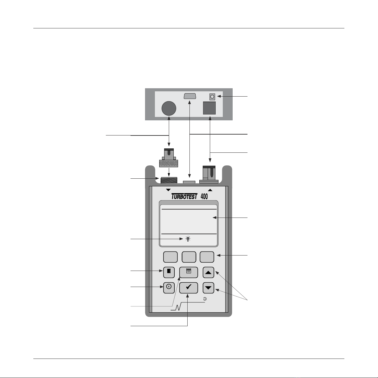
Main Unit .........................................................................................................3
Remote Unit .....................................................................................................4
Section 3: Setup and Operation
Setting an AutoTest Reference ...........................................................................5
Saving Test Results ...........................................................................................6
to create a new file ........................................................................................6
to open an existing file ...................................................................................6
to create a fiber name ...................................................................................6
to specify starting fiber numbers ....................................................................7
to review test results .....................................................................................8
to delete selected files or all files ....................................................................8
to display file and fiber storage statistics ........................................................8
Selecting AutoTest Rules ...................................................................................8
to choose an AutoTest rule .............................................................................9
Selecting AutoTest Direction (one-way or two-way) .............................................9
Setting the Index of Refraction ...........................................................................9
General Setup Options .....................................................................................9
Connecting to a PC ...........................................................................................10
Using the Main Unit as a Power Meter ................................................................10
power meter referencing ................................................................................11
power meter setup ........................................................................................11
Using the Remote Unit as a Light Source ............................................................11
About the T410 or T420 Units ............................................................................11
Section 4: AutoTest Procedures
Conducting an AutoTest .....................................................................................13
Conducting a Loop-Back AutoTest .....................................................................14

ii
T400 User’s Guide
Section 5: Maintenance
Repair and Calibration .......................................................................................15
Cleaning Optical Ports .......................................................................................15
cleaning transmit ports (Tx1 & Tx2) ................................................................15
cleaning receive ports (Rx1 & Rx2) ................................................................16
Replacing Batteries ...........................................................................................16
Section 6: WinTest 400 Software
Software Setup .................................................................................................17
system requirements .....................................................................................17
installing WinTest 400 ...................................................................................17
Getting Started ................................................................................................18
to receive files from the Main Unit .................................................................18
to open, print and save files ...........................................................................19
to edit or enter the default header information .................................................19
Installing New Main and Remote Unit Software ...................................................19
to install new software ...................................................................................19
Section 7: Specifications
TURBOTEST 400 Specifications ........................................................................21
Model T410 Multimode AutoTest Rules ...............................................................22
multimode commercial building (premises) cabling standards ..........................22
multimode application standards ...................................................................22
Model T420 Singlemode AutoTest Rules .............................................................23
singlemode commercial building (premises) cabling standards .........................23
singlemode application standards ..................................................................23
Serial Cable ......................................................................................................24
AC Adapter .......................................................................................................24
List of Figures
Section 2: Functional Description
Figure 2-1. Main Unit .......................................................................................3
Figure 2-2. Remote Unit. ..................................................................................4
Section 3: Setup and Operation
Figure 3-1. AutoTest Referencing ......................................................................5
Figure 3-2. Loop-back AutoTest Referencing .....................................................5
Section 4: AutoTest Procedures
Figure 4-1. AutoTest Setup ...............................................................................13

iii
Figure 4-2. AutoTest Setup (2nd part of a two-way test) .....................................13
Figure 4-3. AutoTest Setup ...............................................................................14
Section 5: Maintenance
Figure 5-1. Cleaning Optical Ports. ....................................................................15
Figure 5-2. Removing Battery Compartment Cover. ...........................................16

iv
T400 User’s Guide
Safety Information
Important Safety Information
WARNING! Use of controls or adjustments other than those specified herein may result
in hazardous radiation exposure.
Model T410 is a CLASS 1 LED product.
Model T420 is a CLASS 1 LASER product.
CAUTION! To avoid serious eye injury, never look directly into the optical outputs of fiber
optic network equipment, test equipment, patch cords, or test jumpers. Always assume
that optical outputs are on.
NOTICE! The T400 contains no user serviceable parts. Except for changing batteries
and cleaning optical ports, this instrument must be returned to Noyes or authorized agents
for repair and calibration.
CAUTION! Proper care in handling should be taken when using any precision optical
test equipment such as the T400. Scratched or contaminated optical connectors can
impact the performance of the instrument. It is important to keep the dust caps in place
when the unit is not being used.
!
!
!

1
Section 1
Section 1: General Information
Thank you for purchasing a Noyes TURBOTEST 400 Series Fiber Optic Certification Test Set. The
purpose of this guide is to explain how to use and maintain your Main and Remote units of either T410
multimode model or T420 singlemode model.
Please check our web site at www.AFLtele.com (click on Products >Noyes Test & Inspection)
for updates to this manual, software updates, and additional application information. If you have any
questions about the T400 units and recommended accessories, or if you need technical or sales support,
please contact Noyes Customer Service.
Contacting Noyes Customer Service
You may call Noyes Customer Service between 8 a.m. and 5 p.m., United States Eastern Time, as
follows:
Tel: 800-321-5298 (North America)
603-528-7780
Fax: 603-528-2025
Web: www.AFLtele.com (click on Products > Noyes Test & Inspection)
Unpacking and Inspection
These instruments have been carefully packed in accordance with standard shipping procedures.
Examine the equipment for damage that may have occurred during shipment. If you find any damage,
or if any of the following items are not included, please contact Noyes.
The T400 package includes:
• T400 Main unit
• T400 Remote unit
• WinTEST software
• Serial cable
• (2) Adapter caps
• (2) AC adapters
• User’s guide
• Carry case

2
T400 User’s Guide
Feature Overview
The TURBOTEST 400 models T410 (multimode) and T420 (singlemode) are designed to quickly test
(AutoTest) loss and length of fiber links, then provide PASS/FAIL results based on your selected standards.
Using the supplied WinTest 400 Software, certification reports can be created based on the latest fiber
standards or user defined rules.
Once a testing standard has been selected, it is only moments after pressing the AutoTest key before
PASS/FAIL results are displayed. AutoTests are based on length, propagation delay, dual wavelength
loss results and user supplied data, such as, the number of splices and connections.
The Main Unit stores test results for up to 1000 fibers in user defined files. To speed the testing process,
the Main Unit can automatically increment fiber numbers.
The Main Unit can also operate like a traditional optical power meter to measure power or loss at 850,
1300, 1310, and 1550 nm. In addition, the Main Unit functions as a stabilized light source at 850 and
1300 nm or as a 2 kHz tone generator for fiber identification applications
Recommended Accessories
Fiber optic test jumpers are required to interface the Main and Remote Units to the fiber under test. Test
jumpers must have the same core and cladding size as the fiber under test. The connector at one end
of the test jumper must interface to the transmit port on the units. The connector on the other end can
be terminated with the same or a different type connector. Test jumpers with a variety of lengths and
connector styles are available from Noyes.
A supply of optical cleaning pads and isopropyl alcohol or a connector-cleaning cartridge is recommended
to clean the optical connectors on the T400 and test jumpers. A supply of fiber optic cleaning swabs or
a can of filtered compressed air is recommended for cleaning connector adapters.

3
Section 2
Section 2: Functional Description
Main Unit
Figure 2-1. Main Unit
NOYES
FIBER SYSTEMS
Menu
F1
Exit
FIBER OPTIC TEST SET
Rx1 Tx2
F2 F3
Power Auto Test
Optical Receive Port (Rx1) -
accepts NOYES thread-on modular
adapter caps.
Optical Transmit Port (Tx2) -
modular adapter
Serial Port - used for data transfer
to a PC and software updates
Modular Adapter Cap
Display - used to show various
screens and setup menus, test
results, and test wavelength.
Exit Key - press to return to the
previous menu/ screen.
AC Adapter Port - this is the
interface for the AC power adapter
REFERENCE IS
OVER 1 DAY OLD
SET REFERENCE
IS RECOMMENDED
OK
Backlight Icon - When displayed,
press F2 key to turn display backlight
On/Off.
Power Key - press to turn the
instrument on or off.
Menu Key - press to display the
Main Menu.
UP and DOWN Keys - used for
menu navigation and to change
parameter value.
Function Keys - the label shown on
the display above the key indicates
the current function assigned to this
key. Press the soft key to activate
the command.
Auto Test Key - press to start an
AutoTest .

4
T400 User’s Guide
Remote Unit
Figure 2-2. Remote Unit.
NOYES
FIBER SYSTEMS
Power
850 & 1300 nm Multimode LED
Model T410
Pass /FailPass /Fail
Low Battery
Autotest
Ready
Tx1 Active
400 Remote
Rx1 Tx2
AC Adapter Port - this is the
interface for the AC power adapter
Power Key - press to turn the
instrument on or off
Optical Receive Port (Rx2) -
accepts NOYES thread-on modular
adapter caps
Optical Transmit Port (Tx1) -
modular adapter
Serial Port - used for data transfer
to a PC and software updates
Modular Adapter Cap
Test Pass/Fail Indicators - based
on selected test rule.
Active Transmit Port Indicator
Ready Indicator - ready to start
AutoTest
Active Autotest Indicator -
AutoTest in progress
Low Battery Indicator - when on,
batteries require replacement

5
Section 3
Section 3: Setup and Operation
This chapter describes how to set the Main and Remote Units for operation, and to program user
preferences.
Setting an AutoTest Reference
Before conducting AutoTests the Main and Remote Units must first be referenced. This procedure should
be done on a daily basis before testing.
1 Clean the test jumper(s) to be used, then choose a reference method:
• AutoTest Referencing: Connect the test jumpers to the Main and Remote Units (Figure 3-1).
OR
• Loop-back AutoTest Referencing: Connect the test jumper to the Main Unit (Figure 3-2). Use this
reference method if the Remote Unit is not available.
Remote Unit Tx1 Test Jumper
Main Unit Tx2
Test Jumper
Figure 3-1. AutoTest Referencing
Rx1 Tx2
Main Unit
Rx2 Tx1
Remote Unit
Figure 3-2. Loop-back AutoTest Referencing
Main Unit Tx2 Test Jumper
Rx1 Tx2
Main Unit
The SETUP (F1) and REF (F3) keys on
the AutoTest screen provide the most
used setup options for conducting
AutoTests.
The Main Menu provides access to
the various other setup menus and
functions.

6
T400 User’s Guide
2 From the AUTOTEST screen press REF (F3). The Main Unit will display the current reference levels
at both wavelengths.
3 Press SET REF (F3).
4 The new reference levels will be displayed.
• If the new reference levels are acceptable (T410: -20 ±1 dBm , T420: -10 ±1 dBm), then
press SAVE (F3).
OR
• If the new reference levels are not acceptable, try cleaning the connectors again, then press
RETRY (F1).
Saving Test Results
This section describes how to identify and save AutoTest results. Each AutoTest will generate test results
for two fibers at both wavelengths. AutoTest results can be labeled with meaningful alphanumeric names
and saved in user defined files. A maximum of 40 files can be stored.
to create a new file
Each file name can have up to 8 characters (letters or numbers). The default name is FILE01.
1 From the MAIN MENU select FILE, then NEW.
2 Use the arrow keys (F1 & F2) and the SELECT (F3) key to enter characters. Use the MAIN MENU
key as a backspace. Press EXIT when finished.
OPTIONAL: To enable the auto file name increment feature enter digits as the last two characters
in the file name.
to open an existing file
To open an existing file to add, review, or retest previously saved results perform the following steps.
1 From the MAIN MENU select FILE, then OPEN.
2 Highlight the desired file, then press SELECT (F3). The file will open and the unit will be ready to
conduct an AutoTest.
to create a fiber name
Each fiber to be tested can be identified by a name and number. The default names and numbers are
FIBER 1 for Side 1 and FIBER 2 for Side 2. The Main Unit can store test results for up to 1,000 fibers
(500 AutoTests).
NOTE: Each fiber name can be up to 8 characters (letters or numbers) in length.
1 From the AUTO TEST screen press SETUP (F1).

7
Section 3
2 Highlight the Side 1 fiber name (e.g. FIBER), then press CHANGE (F3).
3 Use the arrow keys (F1 & F2) and the SELECT (F3) key to enter characters. Use the MAIN MENU
key as a backspace. Press EXIT when finished.
OPTIONAL: To make Side 2 fiber name different from Side 1 name highlight the Side 2 fiber name.
Press CHANGE (F3), then perform step 3 again.
to specify starting fiber numbers
The fiber numbers (Side 1 and Side 2) auto increment from the numbers displayed below the fiber
names. These numbers can be set to any value from 1 to 999.
NOTE: If initial numbers are adjacent (e.g. 11 and 12, or 101 and 102), then they will auto increment
by 2. Otherwise numbers are auto incremented by 1.
EXAMPLE 1: Adjacent Fiber Numbers
Auto Test Side 1 Side 2
1 11 12 Set by user
2 13 14 Auto incremented by 2
3 15 16 Auto incremented by 2
EXAMPLE 2: Non-Adjacent Fiber Numbers
Auto Test Side 1 Side 2
1 200 300 Set by user
2 201 301 Auto incremented by 1
3 202 302 Auto incremented by 1
1 From the AUTO TEST screen press SETUP (F1).
2 Highlight the Side 1 fiber number, then press the + (F2) key to increment, or the - (F1) key to
decrement both fiber numbers. Hold either key for fast adjustment.
Side 1 Side 2

8
T400 User’s Guide
OPTIONAL: To independently change the Side 2 fiber number, highlight it and use the F1 or F2
keys to change.
OR
3 Highlight either number, press CHANGE (F3), then use the F1, F2 and ARROW keys to create the
desired starting numbers for Side 1 and Side 2.
to review test results
NOTE: Be sure that the desired file is already open as previously described.
1 From the MAIN MENU select FILE, then REVIEW RESULTS. The current file name and saved tests
will be displayed.
2 Highlight the desired fiber numbers, then press VIEW (F1). The first Review screen will display the
test rule, pass or fail, loss margin and the length of the tested fibers. To view the additional test
results use the ARROW keys to navigate to the other screens. Depending on the type of test, either
one way (uni-directional) or two-way (bi-directional), 8 or 12 screens of test results will be available
for viewing.
to delete selected files or all files
1 From the MAIN MENU select FILE, then DELETE.
2 A list of files will be displayed.
• Highlight the desired file, then press DELE (F3).
OR
• To delete all files press ALL (F1).
3 Press YES (F1) to confirm deletion, or NO (F3) to cancel the deletion.
to display file and fiber storage statistics
1 From the MAIN MENU select FILE, then STATISTICS. The following statistics will be displayed.
FILES Number of files stored.
FIBERS USED Number of fiber test results stored.
FIBERS FREE Number of additional fiber test results that can be saved.
PCT. FREE Percentage of memory free for storage of additional test results.

9
Section 3
Selecting AutoTest Rules
The Main Unit can compare test results with AutoTest rules based on industry standards, or up to four
user-defined rules. To pass, all parts of the chosen rule must be met. For a complete list of AutoTest
rules refer to Section 7.
to choose an AutoTest rule
1 From the AUTOTEST screen press SETUP (F1) then CHANGE (F3).
2 Scroll to choose a rule from:
• Predefined Standards: To use a predefined standard, use the ARROW keys to scroll to the desired
rule. Select it by pressing SELECT (F3).
OPTIONAL: Press VIEW (F1) to display its test parameters.
NOTE: Some predefined standards require that the number of connections (mated connector pairs)
and splices be specified. The Main Unit will prompt you to enter in this information when required.
The unit will assume that the number of connections and splices in each fiber under test are the
same.
• User-defined Standards: To specify a user-defined standard, scroll to USER-1, USER-2, USER-3
or USER-4 and press EDIT (F1). Use the ARROW keys to highlight the parameter to be changed,
then use the - (F1) or + (F2) key to adjust the selected parameter. When the value is set, press
EXIT.
• No Standard: If you do not want your unit to perform Pass/Fail analysis, scroll to and select NO
RULE.
Selecting AutoTest Direction (one-way or two-way)
AutoTest direction is selectable for one-way (uni-directional) or two-way (bi-directional) measurements.
The default setting is one-way (uni-directional).
1 From the MAIN MENU select OPTIONS.
2 Highlight the DIR: line, then press - (F1) or + (F2) to select the direction.
Setting the Index of Refraction
The index of refraction can be defined from 1.4500 to 1.5500. The default setting is 1.4910 for T410
models and 1.4680 for T420 models.
1 From the MAIN MENU select OPTIONS.
2 Highlight the INDEX: line, then press SELECT (F3).
3 Use the F1 and F2 keys to select digits, and the ARROW keys to increase or decrease the values or
press F3 again to apply the default value. Press EXIT when done.

10
T400 User’s Guide
General Setup Options
To change the following Main Unit options perform the following steps.
1 From the MAIN MENU select OPTIONS. Screen 1 will appear listing the following options. Use the
ARROW keys to highlight the parameter to be changed, then use the - (F1) or + (F2) key to adjust
the selected parameter.
CONTRAST Controls the contrast of the display screen
SOUND Toggles sound on and off
POWER SAVE Toggles the Main Unit power save feature (automatic shut-off after a
period of disuse) on and off
DIR AutoTest Direction. Refer to Section 3.4 for setup information.
INDEX Fiber index of refraction. Refer to Section 3.5 for setup information.
2 Press the either ARROW keys until options screen 2 displays the following.
TIME In 24 hour format. To change it, press SELECT (F3), scroll through the
fields using the F1 and F2 keys, and increase or decrease them using
the ARROW keys. Press EXIT when done.
DATE In day, month, year format. To change it, press SELECT (F3) and change
the fields as in the TIME function, above.
LANGUAGE (future) English is currently the only option.
LENGTH Length Units. Toggle between FEET and METERS using the - (F1) or
+ (F2) key.
Connecting to a PC
To connect the Main Unit to a PC for file transfer using the WinTest 400 software, perform the following
steps.
1 Using the supplied serial cable, connect the Main Unit to the serial port on the PC.
2 Run WinTest 400 software.
3 From the WinTest 400 File menu select Receive All Files.
NOTE: Refer to Section 6.0 for more information on software setup and operation.
4 From the Main Unit’s MAIN MENU select CONNECT TO PC. The Main Unit will connect with WinTest
400 and begin file transfer.

11
Section 3
Using the Main Unit as a Power Meter
To use the Main Unit as an optical power meter and light source, or to use the Main Unit as an optical
power meter with a separate light source, perform the following steps.
power meter referencing
1 Clean and connect the test jumper to the Main Units receive port (Rx1) and the Light Source’s output
port.
2 From the MAIN MENU select POWER METER, then press REF (F2).
3 Press and hold the F2 key to set the reference. The screen will display “Reference Set”.
power meter setup
1 From the POWER METER screen select SETUP (F1) to display the following screen.
2 Using the ARROW keys highlight the parameter to be changed, then use the - (F1) or + (F2) key to
adjust the selected parameter.
3 Press EXIT to enter parameters and return to the POWER METER screen.
Using the Remote Unit as a Light Source
Perform the following steps:
1 The unit must be ON with the Tx1 Active indicator blinking.
2 Press and hold down the Power switch until Ready and Tx1 Active indicators are On continuously
(approximately 5 seconds).
3 Tx1 is now transmitting 1300 nm at about -20 dBm CW from the T410, or 1550 nm at about -10
dBm CW from the T420.
4 Press and then release the Power switch to turn off the transmit source and unit.
F1 F2
OPM SETUP
RX1
MODE dBm, dB, or W
WAVELENGTH 850, 1300, or 1550
Tx2
MODE CW, OFF, or 2 kHz
WAVELENGTH 850 or 1300
(1310 or 1550 in T420)
power meter setup
light source setup

12
T400 User’s Guide
About the T410 or T420 Units
To view general information about the Main and Remote Units follow the steps below. Three screens of
information relating to the Main and Remote Units can be displayed.
NOTE: To view information about your Remote Unit (screen 2) you must link the Remote to the Main
Unit using test jumpers or by connecting both units to a working fiber link.
1 From the MAIN MENU select ABOUT THE T410 or ABOUT THE T420. Screen 1 of 3 will appear
listing the following information about the Main Unit.
VER Software version of the Main Unit.
SN Factory supplied serial number of the Main Unit.
BATTERY Main Unit. If connected to an AC adapter then AC ON is displayed. If powered by
alkaline batteries a life expectancy percentage value will be displayed.
NOTE: When the battery life reaches about 5%, the Main Unit will flash LOW BAT in the upper right
corner of the AutoTest screen. Refer to Section 5 for battery replacement procedures.
2 Press the DOWN ARROW key. Screen 2 of 3 will appear listing the software version and serial number
of Remote Unit if connected. If connected to an AC adapter, then AC ON is displayed. If powered by
alkaline batteries a life expectancy percentage value will be displayed.
NOTE: When the battery life reaches about 5%, the Low Battery LED on the Remote Unit will turn
on. Refer to Section 5 for battery replacement procedures.
3 Again, press the DOWN ARROW key. Screen 3 of 3 will appear listing contact information for
Noyes.

13
Section 4
Section 4: AutoTest Procedures
This section describes how to perform AutoTests using the Main and Remote Units or the Main Unit
with a far end loop-back test jumper.
NOTE: The loop-back procedure calculates the average loss of two fibers and thus is not recommended
for fiber certification.
Conducting an AutoTest
NOTE: To make bi-directional loss measurements, the Main Unit must be setup to perform “two-way”
tests (refer to section “Selecting AutoTest Direction). Refer to Figures 4-1 and 4-2 when conducting the
following procedure. The Main Unit will prompt you to swap test jumpers (Figure 4-2)
1 Set the AutoTest Reference. If this already has
been done, skip to step 2.
2 Select an AutoTest rule.
3 Enter a file name.
4 Enter starting fiber names and numbers.
5 Connect to the fibers under test (Figure 4-1)
NOTE: Once the AutoTest reference has been set
do not disconnect the test jumper from the Main or
Remote Unit transmit ports (Tx2 and Tx1).
6 Conduct the test.
• Press the AUTOTEST key. The Main Unit will
connect with the Remote Unit, conduct the
test and display the results. Use the ARROW
keys to view the additional result screens.
Depending on the type of test, either
one-way (uni-directional) or two-way (bi-
directional), 8 or 12 screens of test results
will be available for viewing.
• Press SAVE (F3) to save the test results.
OR
• Press the AUTOTEST key again to retest the
two fibers.
7 To test additional fibers reconnect the Main
and Remote Units to the next fiber pair then
repeat step 6. The fiber numbers will increment
automatically.
fiber under test
Figure 4-1. AutoTest Setup
side 1
side 2
Rx1 Tx2
Main Unit
Rx2 Tx1
Remote Unit
swap test jumpers at patch
panel NOT at the units
Figure 4-2. AutoTest Setup (2nd part of a two-way test)
side 1
side 2
Rx1 Tx2
Main Unit
Rx2 Tx1
Remote Unit
Table of contents
Other Noyes Test Equipment manuals