NPI ISO-STIM 01B Operating instructions

OPERATING INSTRUCTIONS AND
SYSTEM DESCRIPTION FOR THE
ISO-STIM 01B
STIMULUS ISOLATOR
VERSION 1.8
npi 2016
npi electronic GmbH, Bauhofring 16, D-71732 Tamm, Germany
Phone +49 (0)7141-9730230; Fax: +49 (0)7141-9730240

ISO-STIM 01B User Manual
version 1.8 page 2
Table of Contents
1.Safety Regulations.............................................................................................................. 3
2.Special Safety Notice for High Voltage Instruments.......................................................... 4
3.ISO-STIM 01 B .................................................................................................................. 5
3.1.System Description...................................................................................................... 5
3.2.Description of the Front Panel..................................................................................... 5
3.3.Description of the Rear Panel...................................................................................... 8
3.4.ISO-CAB (optional accessory).................................................................................... 8
3.5.Operation..................................................................................................................... 9
3.5.1.Connections – Noise Reduction..................................................................... 9
3.5.2.Operation Modes............................................................................................ 9
4.Power Supply...................................................................................................................... 10
5.Technical Data ISO-STIM 01B.......................................................................................... 11

ISO-STIM 01B User Manual
version 1.8 page 3
1. Safety Regulations
VERY IMPORTANT:Instruments and components supplied by npi electronic are NOT
intended for clinical use or medical purposes (e.g. for diagnosis or treatment of humans),
or for any other life-supporting system. npi electronic disclaims any warranties for such
purpose. Equipment supplied by npi electronic must be operated only by selected, trained
and adequately instructed personnel. For details please consult the GENERAL TERMS
OF DELIVERY AND CONDITIONS OF BUSINESS of npi electronic, D-71732 Tamm,
Germany.
1) GENERAL: This system is designed for use in scientific laboratories and must be operated
by trained staff only. General safety regulations for operating electrical devices should be
followed.
2) AC MAINS CONNECTION: While working with the npi systems, always adhere to the
appropriate safety measures for handling electronic devices. Before using any device
please read manuals and instructions carefully.
The device is to be operated only at 115/230 Volt 60/50 Hz AC. Please check for
appropriate line voltage before connecting any system to mains.
Always use a three-wire line cord and a mains power-plug with a protection contact
connected to ground (protective earth).
Before opening the cabinet, unplug the instrument.
Unplug the instrument when replacing the fuse or changing line voltage. Replace fuse only
with an appropriate specified type.
3) STATIC ELECTRICITY: Electronic equipment is sensitive to static discharges. Some
devices such as sensor inputs are equipped with very sensitive FET amplifiers, which can
be damaged by electrostatic charge and must therefore be handled with care. Electrostatic
discharge can be avoided by touching a grounded metal surface when changing or
adjusting sensors. Always turn power off when adding or removing modules,
connecting or disconnecting sensors, headstages or other components from the
instrument or 19” cabinet.
4) TEMPERATURE DRIFT / WARM-UP TIME: All analog electronic systems are sensitive
to temperature changes. Therefore, all electronic instruments containing analog circuits
should be used only in a warmed-up condition (i.e. after internal temperature has reached
steady-state values). In most cases a warm-up period of 20-30 minutes is sufficient.
5) HANDLING: Please protect the device from moisture, heat, radiation and corrosive
chemicals.

ISO-STIM 01B User Manual
version 1.8 page 4
2. Special Safety Notice for High Voltage Instruments
HIGH VOLTAGE!!
RISK OF ELECTROCUTION!!
Observe extreme caution when working with this instrument!!!
1) Always connect high voltage power supplies to protective earth!!
2) Do not touch connections unless the instrument is turned off and the capacitance of both
the load and power supply are earthed!!
3) Allow adequate time for discharge of internal capacitance of the power supply!!
4) Do not ground yourself or work under wet or damp conditions!!
5) Servicing should be only done by qualified personnel aware of the hazards!!
6) If in doubt, return to supplier for servicing!!

ISO-STIM 01B User Manual
version 1.8 page 5
3. ISO-STIM 01 B
3.1.System Description
The ISO-STIM 01B stimulus isolation unit is designed for application of extracellular stimuli,
e.g. in brain slices.
The output signal is optically isolated from ground and can either be a constant voltage up to
100 V or a constant current up to 10 mA. A TTL signal at the TRIGGER INPUT generates
one stimulation pulse with adjustable pulse length, amplitude and polarity. An additional
DIRECT INPUT allows the pulse length to be externally controlled, whereas amplitude and
polarity are controlled by the device itself.
For both timing modes the generated pulses can be unipolar or bipolar. In bipolar mode an
interphase gap (IPG) of adjustable length can be inserted between the two pulses.
3.2.Description of the Front Panel
Figure 1: Front panel view of ISO-STIM 01B
In the following description of the front panel elements each element has a number that is
related to that in Figure 1. The number is followed by the name (in uppercase letters) written
on the front panel and the type of the element (in lowercase letters). Then, a short description
of the element is given.

ISO-STIM 01B User Manual
version 1.8 page 6
(1) POWER LED
LED indicating that the ISO-STIM 01D is powered on.
(2) POWER ON/OFF switch
Switch to turn POWER of the ISO-STIM 01D ON or OFF, respectively.
(3) DURATION (ms) digital potentiometer
Potentiometer that sets the duration of the stimulus generated by the built-in timing unit.
(4) OPERATION MODE (BIPOLAR/UNIPOLAR) switch
(5) AMPLITUDE 10-turn potentiometer
Potentiometer that sets the amplitude of the stimulus generated by the internal timing unit. The
maximum range is selected with the OUTPUT rotary switch (#15).
(6) +/- POLARITY switch
Switch for setting the polarity of the stimulus.
(7) OVER + LED
LED indicating that the amplifier is 10% below its positive limit (limit is ±100 V in VOLTAGE
OUTPUT MODE). In CURRENT OUTPUT MODE the limit (±100 V) is set by the
corresponding voltage at the electrode due to Ohm’s Law [V = I*R]), i.e. this control indicates
during an experiment in CURRENT OUTPUT MODE that the electrode resistance increases
and the amplifier is not be able to provide the current which is set if the electrode resistance
increases further.
(8) STIM LED
LED indicating the application of a voltage or current stimulus.
(9) OVER – LED
See (#7).
(10) CAP. COMP trim pot
The CAP.COMP. potentiometer compensates for the input capacitances in isolated CURRENT
output operation only. Capacity compensation is achieved by turning the potentiometer with a
small screw driver clockwise, until the current signal at the oscilloscope is as square as possible.
Important: If the CAP.COMP. is overcompensated in CURRENT MODE, the stimulus isolator
will ring and not work properly!
(11) CHASSIS connector
Jack linked to the CHASSIS. The green banana connector of the optional cable (ISO-CAB) is
connected here.

ISO-STIM 01B User Manual
version 1.8 page 7
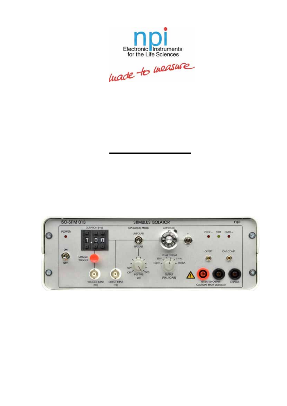
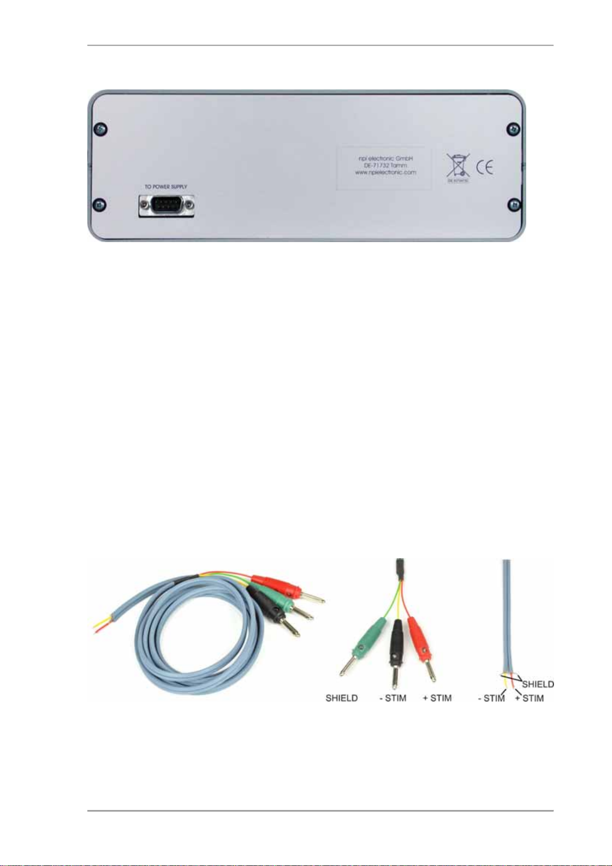
(12) ISOLATED OUTPUT plug (negative)
The ISOLATED OUTPUT signal is available at two plugs (red and black). The polarity of the
+/- POLARITY switch (#6) is not changed, i.e. the red plug is positive (+) if the output polarity
switch is set to +. This signal is completely isolated from ground. The black jack serves as
reference point for the isolated output signal. The black banana connector of the supplied cable
is connected to the black jack and the red to the red jack.
Caution: THIS INSTRUMENT HAS A HIGH VOLTAGE OUTPUT (UP TO 100 V)!!!
Do not touch these pins or bare wires connected to these pins. Always turn power off if you
manipulate devices connected to these pins.
(13) ISOLATED OUTPUT plug (positive)
See (#12).
(14) OFFSET trim pot
Trim-pot to compensate for the OFFSET of the stimulating electrode. It is recommended to
compensate the offset only in a completely warmed up condition i.e. after 30 minutes warm-up
time. Compensation procedure is also possible in current mode.
(15) OUTPUT rotary switch
Switch for selecting current or voltage stimulation and for setting the maximum range to be set
with the AMPLITUDE potentiometer (#5).
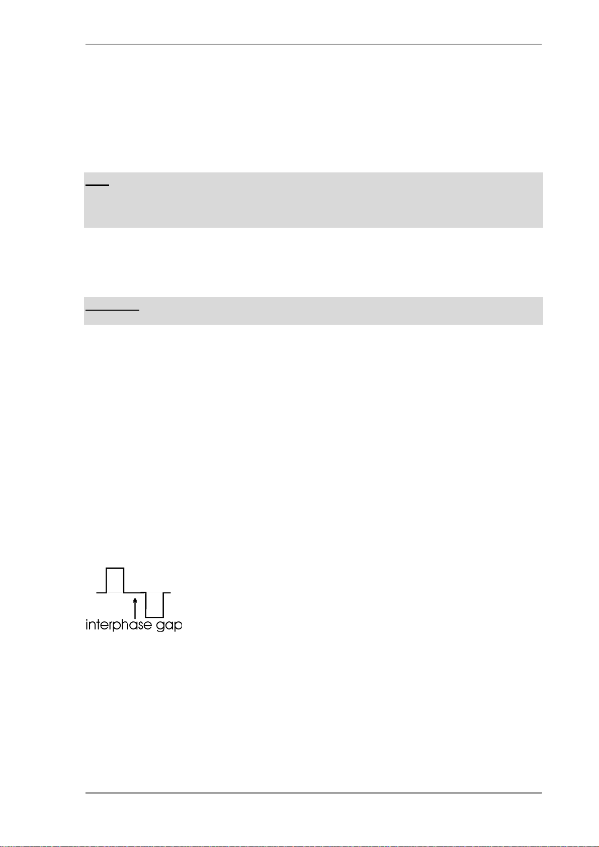
(16) IPG TIME (µs) potentiometer with switch
Potentiometer to select the interphase gap time (IPG) in bipolar stimulation mode (see 3.5.2).
IPG is turned off in the leftmost position (switch).
(17) DIRECT INPUT (TTL) BNC connector
A TTL signal can be fed in here to trigger the output of the ISO-STIM-01D. Amplitude will be
set by #5,#6,#15. In unipolar mode (#4) the output will be active as long as a TTL HIGH signal
is fed into this input. In bipolar mode the output will be active for the time a TTL HIGH signal
is fed into this input. After this time an additional pulse is generated at the output with the same
duration and amplitude but with opposite polarity. The time between these two pulses is set by
the IPG TIME potentiometer (#16).
Important: For bipolar mode to work correctly with DIRECT INPUT TTL, the pulse length
should not exceed 100 ms. Also, the pause between two pulses must have at least the length of
the pulse plus the set IPG time.
(18) TRIGGER INPUT (TTL) BNC connector
A TTL signal can be fed in here to trigger the internal timing unit. Duration of the output signal
is set by the DURATION potentiometer (#3). Amplitude is set by #5,#6,#15.
(19) MANUAL TRIGGER pushbutton switch
This pushbutton has the same functionality as the TTL input (#18), but is for manual operation.

ISO-STIM 01B User Manual
version 1.8 page 8
3.3.Description of the Rear Panel
Figure 2: Rear panel view of ISO-STIM 01B
On the rear panel of the ISO-STIM 01B there is only one SubD connector. This connector is
used to connect the ISO-STIM 01B to its power supply.
3.4.ISO-CAB (optional accessory)
npi provides an optional shielded cable for connection of stimulation electrodes. One end is
equipped with three color coded 4 mm connectors. The red and black connector are connected
to the ISOLATED OUTPUT connectors on the front panel of the ISO-STIM-01 D. Each of
these stimulation lines has a shield which is connected to the common green SHIELD
connector. To reduce noise during recordings, this connector can be connected to the CHASSIS
connector at the ISO-STIM-01 D front panel
The other end of the cable provides open wires, to which different connector types can be
soldered by the user. The red cable is +STIM, the yellow cable is –STIM. The shield is present
as bare wire. Usually, these shield wires are left unconnected on this end of the cable.
Figure 3: ISO-CAB - shielded cable for connection of stimulation electrodes.

ISO-STIM 01B User Manual
version 1.8 page 9
3.5.Operation
3.5.1. Connections – Noise Reduction
The ISO-STIM 01B comes with a power supply with SubD cable, which is connected to the
stimulus isolation device. The corresponding connector at the ISO-STIM 01B is located at the
rear panel.
Note: A possible source of noise is the chassis of the stimulator. In a noisy environment, it may
act as an antenna picking up 50 Hz or 60 Hz noise respectively, especially when operating with
current stimuli. In this case, the noise is substantially reduced if the chassis is connected to
ground (see also #11, Figure 1).
The stimulation electrode is connected to the isolated output (see Figure 1). We recommend to
use a bipolar electrode for stimulating nerve bundles. This will produce only a short stimulation
artifact at the beginning.
Remember: If unipolar electrodes are used the whole slice will be stimulated resulting in a DC
shift of the whole slice.
3.5.2. Operation Modes
BIPOLAR:
The isolator is capable to generate biphasic stimuli by switching the stimulus mode switch to
BIPOLAR ON. In this mode, the stimulus that is set by the user will be followed by a second
stimulus with the same amplitude and duration, but with reverse polarity. There is no delay
between first and second part of the stimulus (except IPG is active, see below). For instance, if
the user sets a positive stimulus of +1 V amplitude and 100 µs duration, this stimulus will be
followed immediately by a negative stimulus of –1 V and 100 µs duration.
BIPOLAR with IPG:
In bipolar mode, a delay between the first and the second, inverse stimulus can be inserted, the
interphase gap (IPG, see Figure 4). IPG time is set by (#16)
Figure 4: Interphase gap (IPG)
OPERATION IN THE 10 mA (max.) RANGE
According to Ohm’s law, with 10 V voltage 10 mA current can be achieved only if the
resistance of the stimulus electrode is not higher than 1 k. Otherwise, the current will be less.

ISO-STIM 01B User Manual
version 1.8 page 10
4. Power Supply
The ISO-STIM 01B is powered with a special power supply (see Figure 5). The power supply
is connected to the ISO-STIM 01B with the provided 9 line SubD cable. It will only fit in one
direction.
Figure 5: Front panel (left) and rear panel (right) view of the ISO-STIM 01B power supply
The power supply is connected to mains with a standard power cord. It has a POWER ON
switch on the rear panel.
Important: Only use the supplied power supply to power the ISO-STIM 01B. Using different
power supplies might result in damage of ISO-STIM 01B and/or power supply.
Important: This power supply is designed for use with the ISO-STIM 01B only. Using it
differently might result in damage of the power supply.

ISO-STIM 01B User Manual
version 1.8 page 11
5. Technical Data ISO-STIM 01B
Input resistance: 2 k
Output: unipolar or bipolar, selected by toggle switch
Output voltage: ±100 V max., isolated
Output current: ±10 mA max., isolated
IPG (interphase gap): 50 … 500 µs
Power requirements: 100 … 240 V, AC, only use supplied power supply
Fuses: Power Supply: 1.25 A, slow
Dimensions: ISO-STIM 01B: 246 x 188 x 89 mm³ (W x D x H)
Power Supply: 103 x 169 x 59 mm³ (W x D x H)
Table of contents
Other NPI Laboratory Equipment manuals