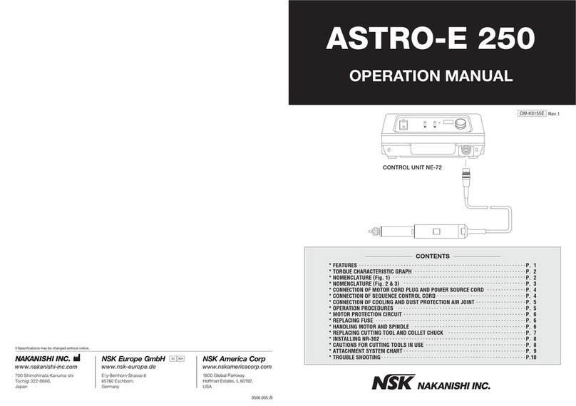
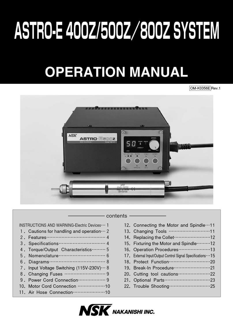
NSK Nakanishi ASTRO-E 400 User manual

ASTRO-E 400 / 500 SYSTEM
OPERATION MANUAL
P.1-2 INSTRUCTIONS AND WARNINGS
P.3-4 SPECIFICATIONS
COMPONENT NAMES
P.5
INSTRUCTIONS FOR SWITCHING VOLTAGE
P.6 CONNECTION OF MOTOR CORD AND
POWER CORD
CONNECTION OF AIR HOSE
P.7 SEQUENCE CONTROL CONNECTION
TRIP TERMINAL
P.8 MOUNTING BRACKET
OPERATION PROCEDURES
P.9-10 OPERATION PROCEDURES
CHANGING FUSES
CONNECTING SPINDLE TO MOTOR
REPLACING CUTTING TOOL
P.11 REPLACING COLLET CHUCK
INSTALLATION OF SPINDLE
P.12 SYSTEM CHART
P.13 ACCESSORIES
P.14 TROUBLESHOOTING
CONTENTS
OM-K0054E
Rev.3
'04.04.005.◯A
※Specifimations may be changed without notice.
HEAD OFFICE&FACTORY :700 Shimohinata,Kanuma-shi,Tochigi-ken 322-8666,Japan
TEL:0289-64-3380 FAX:0289-62-5636
TOKYO OFFICE:6F MY Bldg.,1-13-3 Ueno,Taito-ku,Tokyo110-0005,Japan
TEL:03-3835-2892 FAX:03-3835-2856
http://www.nsk-nakanishi.co.jp e-mail: box@nsk-nakanishi.co.jp
NSK AMERICA CORPORATION
700 B Cooper Court
Schaumburg, Illinois 60173
Tel.(847)843-7664 Fax.(847)843-7622

GROUNDING
PIN (A) (B)
(C)
(D)
ADAPTER
GROUNDING
MEANS
METAL SCREW
COVER OF GROUND
OUTLET BOX GROUNDING
PIN
WARNING !
When using electric tools, basic safety precautions should always be followed to reduce the risk of fire, electrical
shock and personal injury, including the following.
Read all these instructions before operating this product and save these instructions.
A. GROUNDING INSTRUCTIONS
1. In the event of a malfunction or breakdown, grounding provides a path of least resistance for electric current
to reduce the risk of electric shock. This tool is equipped with an electric cord with a grounding conductor
and a grounding plug. The plug must be plugged into a matching outlet that is properly installed and
grounded in accordance with all local codes and ordinances.
2. Do not modify the plug provided - if it will not fit the outlet, have the proper outlet installed by a qualified
electrician.
3. Improper connection of the grounding conductor can result in electric shock. The conductor with insulation
having an outer surface that is green with or without yellow stripes is the grounding conductor. If repair or
replacement of the electric cord or plug is necessary, do not connect the grounding conductor to a live
terminal.
4. Check with a qualified electrician or service person if the grounding instructions are not completely
understood, or if in doubt as to whether the tool is properly grounded.
5. Use only 3-wire extension cords that have 3-prong grounding plugs and 3-pole receptacles that accept the
tool's plug.
6. Repair or replace damaged or worn cord immediately.
7. This tool is intended for use on a circuit that has an outlet that looks like the one illustrated in Sketch A in
Figure(below)(115V). The tool has a grounding plug that looks like the plug illustrated in Sketch A in Figure
(below). A temporary adapter, which looks like the adapter illustrated in Sketches B and C, may be used to
connect this plug to a 2-pole receptacle as shown in Sketch B if a properly grounded outlet is not available.
The temporary adapter should be used only until a properly grounded outlet can be installed by a qualified
electrician. The green-colored rigid ear, lug, and the like, extending from the adapter must be connected to a
permanent ground such as a properly grounded outlet box.
Grounding Method
Minimum gage for cord
Ampere Rating
Volts Total length of cord
120V
240V
More
Than
Not
More
Than
Only the applicable parts of the Table need to be included. For instance,
a 120-volt product need include the 240-volt heading.
IMPORTANT INSTRUCTIONS AND WARNING - Electric Devices
8. USE PROPER EXTENSION CORD. Make sure your extension cord is in good condition. When using an
extension cord, be sure to use one heavy enough to carry the current your product will draw.
An undersized cord will cause a drop the line voltage resulting in loss of power and overheating.
Table(below)shows the correct size to use depending on cord length and nameplate ampere rating.
If in doubt, use the next heavier gage. The smaller the gage number, the heavier the cord.
0
6
10
12
6
10
12
16
18
18
16
14
16
16
16
12
16
14
14
14
12
12
Not Recommended
P.1
7.5m(25ft.)15m(50ft.)30m(100 ft.)45m(150 ft.)
15m(50ft.)30m(100ft.)60m(200 ft.)90m(300 ft.)
B. OTHER WARNING INSTRUCTIONS
1. For your own safety read instruction manual before operating tool.
2. Wear eye protection.
3. Replace cracked wheel immediately.
4. Always use guards and eye shields.
5. Do not overtighten wheel nut.
6. Use only flanges furnished with the grinder.
7. REMOVE ADJUSTING KEYS AND WRENCHES. Get in the habit of checking to see that keys and adjusting
wrenches are removed from tool before turning it on.
8. KEEP WORK AREA CLEAN. Cluttered areas and benches invite accidents.
9. DON'T USE IN DANGEROUS ENVIRONMENT. Don't use power tools in damp or wet locations, or expose
them to rain. Keep work area well lighted.
10. Risk of injury due accidental starting. Do not use in an area where children may be present.
11. DON'T FORCE TOOL. It will do the job better and safer at the rate for which it was designed.
12. USE RIGHT TOOL. Don't force tool or attachment to do a job for which it was not designed.
13. WEAR PROPER APPAREL. Do not wear loose clothing, gloves, neckties, rings, bracelets, or other jewelry
that might get caught in moving parts. Nonslip footwear is recommended. Wear protective hair covering to
contain long hair.
14. ALWAYS USE SAFETY GLASSES. Everyday eyeglasses only have impact resistant lenses, they are NOT
safety glasses. Also use face or dust mask if cutting operation is dusty.
15. SECURE WORK. Use clamps or a vise to hold work when practical. It's safer than using your hand and it
frees both hands to operate tool.
16. MAINTAIN TOOLS WITH CARE. Keep tools sharp and clean for best performance and to reduce the risk of
injury to persons. Follow instructions for lubricating and changing accessories.
17. DISCONNECT TOOLS before servicing; when changing accessories, such as blades, bits, cutters, and like.
18. REDUCE THE RISK OR UNINTENTIONAL STARTING. Make sure switch is in off position before plugging in.
19. USE RECOMMENDED ACCESSORIES. Consult the owner's manual for recommended accessories. The use
of improper accessories may cause risk of injury to persons.
20. NEVER LEAVE TOOL RUNNING UNATTENDED. TURN POWER OFF. Don't leave tool until it comes to a
complete stop.
21. For recommended operating speed for various applications, please follow the instructions of bur
manufacturers.
22. Use Accessories suitable for Max. 40,000min-1
(ASTRO-E 400)and Max. 50,000min-1
(ASTRO-E 500).
C. Important Instructions and Warnings about ASTRO-E 400 / 500 SYSTEM
1. LOCATING CONTROL UNIT NE52
The control unit NE52, NE52-500 is equipped with vents and a cooling fan to prevent overheating of its
electronic circuitry. When choosing a mounting position, make sure that these vents at the rear of panel are
kept open and free of obstruction so that air may flow freely. Failure to do so will result in overheating and
failure of system.
2. RESET SWITCH
Continuous "KICK OFF" of reset switch is an indication that the ASTRO-E 400 / 500 system is being used
beyond its envelope of operation. Continuous use under such circumstances will only produce poor
product finish and system failure.
3. SPEED AND TORQUE
・If speed requirements are under 2,000 min-1, it is recommended that reduction gears ARG-01E or ARG-
02E be used to assure proper torque at low end speeds.
・
Do not exceed 1.5 cN・m(in.-oz.)load for prolonged periods of time as this will overheat the EM-401
,
EM-405
,
EM-
401A,EM-501,EM-505,EM-501A motor.
4. TOOLING
・When making a choice of tooling to be used with the ASTRO-E 400 / 500 system, make sure that such
tooling are rated to maximum speeds above 40,000 min-1 / 50,000 min-1.
・When using mounted stones, make sure that stones are properly dressed to assure good product finish.
An undressed stone will cause bearing stress, vibration and poor finish.
・Never use tooling that is bent chipped, or unrated as this will only result in a hazardous condition to
operator and create a malfunction of the ASTRO-E 400 / 500 system.
・Never extend tooling more than 13mm from base of collet cap as this will cause vibration on the tooling
and good finish of product will not be achieved.
P.2
ASTRO-E400/K0054E.3/e/02.0706.12.2211:24ページ3

!3SequenceControlJoint
118
100
218
(17.4)
φ30 0
-0.01
φ16.9
(8.58")
Fig.2
Fig.3
φ16.9
(17.4) (6.3")
160
φ30 0
-0.01
!4InletwithPowerFuse
!2AirInletJoint
!0MotorCoolingJoint
oSpeedControlSelectorSwitch
!1ConnectorforMotorCord
!5TripTerminal
P.3 P.4
◆SPECIFICATION
qControlUnit(NE52/NE52-500)
wSpeedDisplay
eSpeedControlKnob
rResetActivationCheckLamp
tManualFWD/REVandCircuit
BreakerReleaseSwitch
yMANUAL/AUTOSelectorSwitch
uPowerLamp
iPowerSwitch
MOTORANDSPINDLE
◆COMPONENTNAMES
Fig.1
PRODUCT
MODEL
POWERSOURCE
POWERCONSUMPTION
WEIGHT
DIMENSION
MOTORMODEL
SPINDLEMODEL
SPEED
MAX.POWEROUTPUT
WEIGHT(incl.CORD)
DIMENSION
ASTRO-E400 ASTRO-E500
NE52
115/230VACSwitchable50-60Hz 115/230VACSwitchable50-60Hz
170W
5.5kg(12.1lbs)
W301×D262×H97A
EM-401,
EM-405,
EM-401A
NR-402E
0-40,000min-1
210W
1,120g(39.5oz.)
φ30×218A
EMS-3041,
EMS-3045,
EMS-3040A,
EMS-3051,
EMS-3055,
EMS-3050A
195W
1,000g(35.3oz.)
φ30×160A
170W
5.5kg(12.1lbs)
W301×D262×H97A
EM-501,
EM-505,
EM-501A
0-50,000min-1
210W
1,120g(39.5oz.)
φ30×218A
EMS-3052,
EMS-3056,
EMS-3052A
195W
1,000g(35.3oz.)
φ30×160A
NE52-500
NR-452E
EMSSERIES
EM−5 01,505
Torque(cN・m)
Speed(×103min-1)
5045
Power
0
150
200
100
50
Torque
40300
8
7
20
6
2
5
3
2515 35105
1
4
Power(W)
Power(W)
Power
40
3020 2515 35105
4
1
3
5
2
6
7
8
0
Torque
50
100
200
150
0
EMSSERIES
EM−4 01,405
Torque(cN・m)
Speed(×103min-1)
ASTRO-E400/500CHARACTERISTICCURVES
Cautionsforeachmotorandspindle.
・Angular bearings are used for NR-402, EM-401 and EMS-3041.
・Ceramic bearings are used for NR-452E, EM-501, EMS-3051, EMS-3055 and EMS-3050A.
・Mid-joint connectors are equipped with EM-405, EMS-3045, EMS-3055, EM-505 and EMS-3056.
・EM-401A, EMS-3040A, EM-3050A and EMS-3052A, for HES high speed spindle, have emergency connectors.
・EMS is spindle united with motor.
!6VoltageSwitchingTerminal115/230V
ASTRO-E400/K0054E.3/e/02.0706.12.2211:24ページ5

Cooling air protects the motor and spindle from debris. Care should be
exercised to prevent cutting oil into the spindle, when Power Switch
i
is OFF,
because cooling air stops and does not go to the spindle.
P.6
Fig.8
◆CONNECTIONOFAIRHOSE
¡Connectaφ4.0airhosefromthemotortoMotorCoolingJoint !0 atthebackofthe
controlunitbyusingaφ6/φ4 adaptor.
Connecttheairsupplyjointof AirLineKit(AL-0201)andAirInletJoint !2 byusinga φ6.0
airhose,andsupplyairbetween0.2‐0.5MPa(2-5kg/cm2・29-71psi).
Themotorwouldnotrotatewithoutcoolingairforprotectingthemotor.
¡Whenusingtheselectorunit,insertaφ6.0airhosetoMotorCoolingJoint!0 attheback
ofthecontrolunit. Air pressureshouldbe0.5MPa.
(71psi).
ToAirCompressor
AirSupplySide
BacksideofUnit
!2
!0
CAUTION
Connecting
plate
P.5
●HowtouseVoltageSwitchingTerminal!6(PowerSupplyVoltage)
A)115VINPUT(110V-120V)
Connectupperandbottomtwoterminals
marked115Vbyconnectingplatesrespectively.
(SeeFig.5.)
B)230VINPUT(220V-240V)
Connectmiddletwoterminalsmarked230Vby
connectingplate.(SeeFig.6)
115V
115V
230V
115V
115V
230V
Fig.6
Fig.5Fig.4
Fig.7
◆CONNECTINGMOTORCORDANDPOWERCORD
ConnectthemotorcordtoConnectorforMotorCord!1 andfastenwiththecordnut.(
Fig.7)
Plugthepowercordfor115Vor230VinInletwithPowerFuse!4.
!2
!5
!0
!1 !4
VoltageSwitchingTerminal
◆INSTRUCTIONFORSWITCHINGVOLTAGE
WARNING
Thisdevicecanbeusedoneither115Vor230V.Besuretofollowthe
instructionbelowforswitchingvoltage,becauseusingwiththevoltageother
than115Vand230Vmaycausemalfunction,electricshockandfire.
Connectingplates
ASTRO-E400/K0054E.3/e/02.0706.12.2211:24ページ7

P.7
Bracket
Bracket
Screw
Fig.11
◆OPERATIONPROCEDURES
Operation‐1ManualOperation(SeeFig. 11)
aTurnPowerSwitchiON.(GreenLampulights.)
sSelectMANUAL/AUTOSelectorSwitchytoMANUALside.
dAdjustSpeedControlKnobetothelowest(counterclockwise)
fSelectManualFWD/REVSwitch ttoeitherFORWARDorREVERSEdirection.
gTurnSpeedControlKnobeclockwisegraduallyandadjusttorequiredmotorspeed.
SpeedDisplaywshowsthemotorspeedthrough1-40(
ASTRO-E400
),1-50(
ASTRO-E500
).
SpeedDisplaywallowstoconfirmrequiredmotorspeedforgrindingandcutting.
hTostopoperation,selectManualFWD/REVSwitchttoOFF.(Torestart,repeatthesteps
ofd,fandg.)
w
e
r
ty
u
i
S K
NAKANISHI INC.
AUTO
TRIP
10V
SPEED
FRONT
EXIT
AIRIN
+
+
-
-
COM
R/L
ON/OFF SPEEDCONTROL
AIROUT
100V
100V
200V
oBacksideofUnit
P.8
Fig.9
DC0 10V
˜
50KΩ
10V
SPEED
DC24V
DC24V
R/L
COM
ON/OFF
510Ω
510Ω
3KΩ
3KΩ
Fig.10
TRIP
CircuitDiagram
ofControlUnit
◆SEQUENCECONTROLCONNECTION
◆TRIPTERMINAL!5
ThetransistorconnectedtotheTRIPterminalsisturnedon,whenRESETfunctionsduring
motorrotation.
Thisfunctioncanbeusedtocontroltheothermachinesthatareusedwiththismotor.
ThemaximumratingofthetransistorisVcEo=50VDC,Ic=50mAandPc=100mW.Donot
exceedthemaximumrating.
・
Speedbetween0-40,000min-1
(ASTRO-E400),
or0-50,000min-1
(ASTRO-E500)canbe
controlledvariablywhenanexternalvoltage
(0-10VDC,1mAMax.)isconnectedtothe
SPEEDterminal.(Fig.9)
・Motorrunsinthereversedirectionwhen
24VDCisappliedbetweentheR/LandCOM
terminals,andintheforwarddirectionwhen
0VDCisapplied.(Fig.9)
・Motorstartstorunwhen24VDCisapplied
betweenON/OFFandCOMterminals,and
stopswhen0VDCisapplied.(Fig.9)
◆MOUNTINGBRACKET (FORRACKMOUNT)
Remove4screwsfromeachsideofleftandrightonthecontrolunitandfixthebracketon
thecontrolunitasshownonFig.11.
CAUTION
¡The motor stops rotation to protect when overloading and Red Lamp rlights.
Release circuit breaker after lightening loading.
¡
How to release circuit breaker
Select Manual FWD/REV and Circuit Breaker Release Switch
t
to RESET and
Red Lamp
r
is off. Select either direction of FWD/REV Switch
t
for restart.
!3
ASTRO-E400/K0054E.3/e/02.0706.12.2211:24ページ9

P.10
◆CONNECTINGSPINDLETO MOTOR
Alignthethreadsonthefrontendofthemotorandtherearofthespindle,andturnthe
spindleclockwise.Ifthedriveshaftofthemotordoesnotengagethedrivedogonthe
spindle,youmayonlybeabletoturnitabout2turns.DONOTFORCE.Turnthespindle
backafewthreads,rotatethespindlebyhandtoengagethedriveshaftandthedrivedog,
andscrewthemtogether.
Transmissionclutch
Turn
Tighten Fig.13
◆CHANGINGFUSES
INLETBOXhasafuse(250V-T2.5A)init.Itis
removedbysqueezingthesmalllatchesatboth
sidesofthefuseboxandpullout.
Fig.12
P.9
Operation‐2AutomaticOperation(SeeFig.11)
aTurnPowerSwitchiON.(GreenLampulights.)
sSelectMANUAL/AUTOSelectorSwitchytoAUTOside.
¡Operateundertheexternalcontrolequipment(sequencecontrol).SeeP7 Connecting
SequenceControlTerminal!3 forconnection.
¡WhenSpeedControlSelectorSwitchoisonEXTside,themotorspeedandswitching
FWD/REVcanbecontrolledunderSequenceControl.
¡Only motor speed can be controlled by Speed Control Knob e, when Speed Control
SelectorSwitchoisonFRONTSPEEDCONTROLside.
¡ManualFWD/REVSwitchtofthecontrolunitcannotbeused.
CAUTION
¡
The motor would stop rotation without Red Lamp
r
lighting or with Green
Lamp
u
off, if it receives overloading frequently. Leave the motor for a while till
Red Lamp
r
would light and follow the procedure to release the circuit breaker.
CAUTION
¡The motor stops rotation to protect when overloading and Red Lamp rlights.
Release circuit breaker after lightening loading.
¡How to release circuit breaker
Apply 0 VDC(OFF)ON/OFF and COM terminal(Fig. 9)for reset and Red Lamp
ris off. Apply 24 VDC(ON)ON/OFF and COM terminals for re-start.
CAUTION
Clean hands and the connecting parts, before conneting the spindle to the motor
(the speed reducer)to prevent entry of debris into the motor and spindle.
◆REPLACINGCUTTINGTOOL
a Settheprovidedspannerwrench12A onthespindle.
s Placetheprovidedspannerwrench14A onthecolletcapandturnitcounterclockwiseto
loosenthecolletchuck,andpulloutthecuttingtool.
d Insertanewcuttingtoolandfastenthecolletchuckclockwisebyturning.
Tighten
Loosen
Tool
Spindle
ColletCap
Fig.14
ASTRO-E400/K0054E.3/e/02.0706.12.2211:24ページ11

◆ASTRO-E400/500 SYSTEMCHART
ColletCapK-265
AxisforDrillChuckDCH-J0K
(Jacob'staperNo.0)
ColletChuckCHK-□□
AxisforMetalSawKCH-03
GrindstoneAGM-03
ColletChuckCHP-3.175
AxisforMetalSawKCH-02
ColletChuckCHS-□□
ColletChuckCHA-□□
ColletCapK-263
ColletChuckCH8-□□
AutomaticToolReplacementSpindle
NR-410EATC・NR-420EATC
Spindle
NR-402E・NR-452E
Spindle
NRL-300E
90゜AngleSpindle
RAS-150E
(1
/
2.67)
SpeedReducer
ARG-02E
SpeedReducer
ARG-01E
MotorEM-401
EM-405(
Cordwithintermediateconnector
)
EM-501
EM-505(
Cordwithintermediateconnector
)
SelectorUnitNE62
ControlUnitNE52
NE52-500
90゜AngleSpindle
RA-270E
(1/1.5)
90゜AngleSpindle
RAW-70E(1
/
6)
RAW-270E(1
/
1.5)
90゜AngleSpindle
RA-150E(1
/
2.67)
(1
/
4)
(1
/
16)
MotorSpindle
EMS-3041・EMS-3051
EMS-3052
MotorSpindle(
Cordwithintermediateconnector
)
EMS-3045・EMS-3055
EMS-3056
AirLineKit
AL-0201
SelectorUnitNE135
P.12
P.11
◆REPLACINGCOLLETCHUCK
a Loosenandremovethecolletcapwithcuttingtoolaccordingtothe"ReplacingCutting
Tool"stepsabove.
s Removethecuttingtoolfromthecolletchuck.
d Toremovethecolletchuckfromthecolletcap,holdthecolletcapinonehandandincline
thecolletchucktowardthespannerslitofthecolletcap.
f Tomountanewcolletchuck,inclinethecolletchucktowardthespannerslitofthecollet
capandinsert.
*
①Standardcolletchuckisφ3.0A.
(Standardcolletchuckisφ3.175AforUSA.)
①Optionalcolletchucksareavailableinφ0.1Aincrementfromφ0.5A-φ6.0Aand
φ2.35A(φ3/32"),andφ3.175A(φ1/8"),andφ6.35A(φ1/4")
①OptionalColletChuckNo.CHK-□□(FillI.D.in□□)
Tool
Spindle
Loosen
ColletCap
Fig.15 Fig.16
SpannerSlit
ColletChuck
Push
ChuckCap
◆INSTALLATIONOFSPINDLE
Toinstallthespindleonaholder,theinstallationasshowninFig.17isrecommended.
(Ifitisnotpossible,installitasshowninFig.18.)Donotusemountingscrewspushing
directlyonthespindleasshowninFig.19, becauseitcoulddamagethehousingandmay
resultinfailureofrotationandoverheating.
Fig.17 Fig.18 Fig.19
FasteningBoltFasteningBolt
Slit
FasteningBolt
SlitofBushing
BushingwithSlit
φ30
+0.03
0
φ30
+0.03
0
φ30
+0.03
0
ASTRO-E400/K0054E.3/e/02.0706.12.2211:24ページ13

Checkvoltagebetween0V-10VDC.
P.14
◆TROUBLESHOOTING
Checkthefollowingtableforanyabnormalities.Ifproblempersists,pleasecontactyourlocal
distributorforservice.
〈ControlUnitNE52,NE52-500andMotor〉
Trou-
ble CheckPoint Cause Countermeasure
PowerLampdoesnotlight
whenpowerswitchisON.
Powercordisunplugged. Connectpowerplug.
Continuousoverloading. Systemwillautomaticallyturnon
afterapausingperiod.
RedLamplights.
Lowcoolingairpressureornoair
flow.
Releaseactivatedcircuitbreaker.
(Page9)
Plugmotorcordsecurelyandtighten
motorcordnut.
Ifmotorcordisnotproperlyplugged
andsecured,RedLampwillnotturn
off.
Thecircuitbreakerwillautomatically
resetafterapprox.20minutes.When
thecircuitbreakerresets,RedLamp
willturnon,thenresetthebreakerby
switchingtheFWD/REVSwitchtothe
neutralpositionandthenbacktothe
desireddirectionofrotation.
Regulateairpressurebetween0.2-
0.5MPa.Properlyconnectairinput.
EXTpositionselected.
ON/OFFterminalisnotproperly
connected.
R/Lterminalisnotproperly
connected.
SpeedControlSelectorSwitchon
EXTposition.
WhenR/Lterminalis
ON,motordoesnot
operate.
Manualspeedcontrol
onfrontpanelisnot
operational.
ConnectON/OFFterminalproperly.
ConnectR/Lterminalproperly.
TurnSpeedControlSelectorSwitch
toFRONTSPEEDCONTROL.
RedLampdoes
notturnoffeven
afterreleasing
circuitbreaker.
RedLampisoff
fanrunningat
highspeed.
Motorcordnutis
notsecured.
Multipleoverloads
thermaloverload.
Motordoesnotrunwhen
R/Lterminalisselected
onmanualmode.
or
Motordoesnotrunwhen
ON/OFFterminalat
sequencecontrolis
selectedonremotemode.
ON/OFFterminal:
Onposition,
nopower
Motor and Handpiece do not run.
Pilot Lamp Lights
Sequence Terminal
〈Spindle〉
Trouble Cause Countermeasure
Excessiveburrun-out.
Foreignparticlesordirtinsidecollet
chuckandspindle. Cleancolletchuckandspindle.
Colletchuckisnotproperly
positionedinsidecolletcap. Securecolletchuckintocolletcap
asshowninFig.16inPage11.
Bentburorunbalancedgrindingstone.
Replacebur.
Wornbearings. ReturntoServiceCenter.
ReturntoServiceCenter.
Duringoperation,highnoiselevel
andvibrationpresent.
Foreignobjectsinbearings.Worn
bearings.
Bentburorunbalancedgrindingstones
.Replacebur.
Blowoutoffuse. Changefuses.(Page9)
◆ACCESSORIES
■ColletChucksList
Product Model SizeofInsideDiameterd(
mm
)Fitto
23.5
d
I.D.=d
CHS-□□
φ2.35,φ3.0,φ3.175 RA-270E
φ0.8-φ2.9every0.1A
I.D.=d
CHP-□□
NR-410E ATC
NR-420E ATC
I.D.=d
CH8-□□
RA-150E
φ10.5
20
d
I.D.=d
CHK-□□
withColletCapK-265
φ2.35,φ3.0,φ3.175,φ6.0,φ6.35 NR-402E・NR-452E・RAS-150E
EMS-3041
・
EMS-3051
・
EMS-3045
・
EMS-3055
EMS-3040A
・
EMS-3050A
EMS-3052・EMS-3056・EMS-3052A
φ0 .8-φ5.9every 0.1A(Otherthanabove)
φ2.0,φ3.0,φ3.175
34.4
d
φ2.35,φ3.0,φ3.175
φ0.8-φ2.9every0.1A
34.4
d
■SpecialAxisList
I.D.=d
CHA-□□
withColletCapK-263
φ2.35,φ3.0,φ3.175
φ0 .8-φ4.0every 0.1A(Otherthanabove)
RAW-70E
・
RAW-270E
φ7.4
17
d
Product Description・Model
Special Drill Chuck Axis; DCH-J0K
For drill Chuck Jacob's Taper No. 0
Run-out Accuracy : Within 0.05A
56
Grindstone Axis AGM-03
Run-out Accuracy : Within 0.02A
For Grindstone with φ5.0AI.D.
48
φ5
Special Metal Saw Axis KCH-03
Dimensions of Metal Saw φ1/4(I.D.)×φ1.18"(O.D.)
Run-out Accuracy : Within 0.02A
φ6
54.5
φ6
50
Special Metal Saw Axis KCH-02
Dimensions of Metal Saw φ1/4"(I.D.)×φ1.18"(O.D.)
Run-out Accuracy : Within 0.02AOrder AS11436 forφ1/4"
Special Axis for Drill Chuck DCH-J0A
Drill Chuck For Jacob's Taper No. 0
Run-out Accuracy : Within 0.05A
Grindstone Axis AGM-01A
Run-out Accuracy : Within 0.02A
For Grindstone with φ5.0AI.D.
41
φ5
φ6
50.5
Special Axis for Metal Saw KCH-01A
Demention of Metal Sawφ6.0(I.D.)×φ30A(O.D.)
Run-out Accuracy : Within 0.02A
NR-402E・NR-452E・RAS-150E
EMS-3041・EMS-3051・EMS-3045・EMS-3055
EMS-3040A・EMS-3050A
EMS-3052・EMS-3056・EMS-3052A
NR-402E・NR-452E・RAS-150E
EMS-3041・EMS-3051・EMS-3045・EMS-3055
EMS-3040A・EMS-3050A
EMS-3052・EMS-3056・EMS-3052A
RA-150E
Fitto
NR-402E・NR-452E・RAS-150E
EMS-3041・EMS-3051・EMS-3045・EMS-3055
EMS-3040A・EMS-3050A
EMS-3052・EMS-3056・EMS-3052A
RAW-70E・RAW-270E
RAW-70E・RAW-270E
RAW-70E・RAW-270E
51
※Axis ofφ5 Aandφ8 Aare also available for metal saw in addition toφ6 A.
P.13
ASTRO-E400/K0054E.3/e/02.0706.12.2211:24ページ15
This manual suits for next models
3
Table of contents
Other NSK Control Unit manuals
Popular Control Unit manuals by other brands

Vag
Vag GA Industries 939SS Installation, operation and maintenance manual

Lucent Technologies
Lucent Technologies LINEAGE 2000 FPS product manual

National Instruments
National Instruments NI 9871 Getting started guide

Dometic
Dometic Q3 Operation manual

ITW Linx
ITW Linx SurgeGate MCO4 Product instructions

Eaton
Eaton MFD-CP8 Series Instruction leaflet

schmersal
schmersal AZR 31S1 Series operating instructions

IMI TA
IMI TA TA-FUS1ON-C manual

esera automation
esera automation 1-Wire Hub III DC user guide

Weinmann & Schanz
Weinmann & Schanz Heatapp! System Installation instruction

esera
esera 11108 quick guide

Honeywell Home
Honeywell Home AQUATROL AQ252 owner's guide