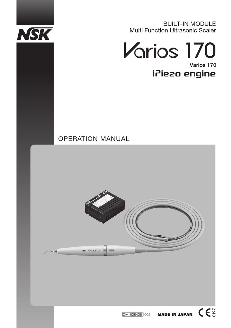
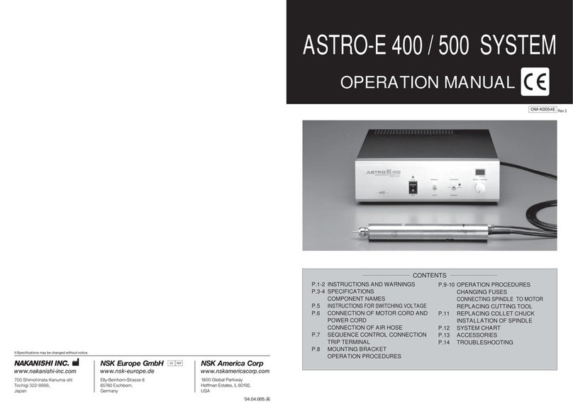
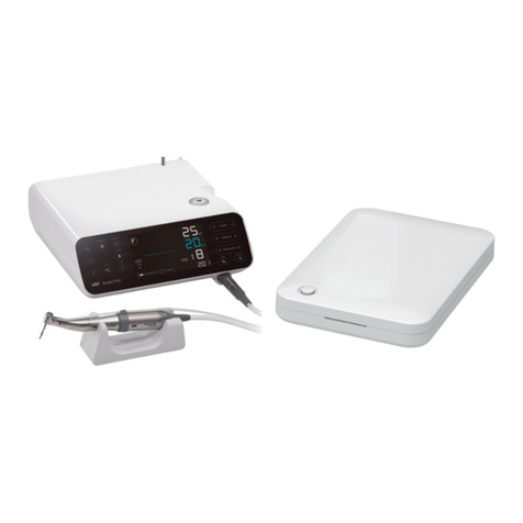
NSK ASTRO-E 250 User manual

ASTRO-E 250
OPERATION MANUAL
CONTROL UNIT NE-72
CONTENTS
※Specifications may be changed without notice.
HEAD OFFICE&FACTORY :700 Shimohinata,Kanuma-shi,Tochigi-ken 322-8666,Japan
TEL:0289-64-3380 FAX:0289-62-5636
TOKYO OFFICE:6F MY Bldg.,1-13-3 Ueno,Taito-ku,Tokyo110-0005,Japan
TEL:03-3835-2892 FAX:03-3835-2856
http://www.nsk-nakanishi.co.jp e-mail: box@nsk-nakanishi.co.jp
05.06.005.◯A
* FEATURES ‥‥‥‥‥‥‥‥‥‥‥‥‥‥‥‥‥‥‥‥‥‥‥‥‥‥‥‥‥‥P. 1
* TORQUE CHARACTERISTIC GRAPH ‥‥‥‥‥‥‥‥‥‥‥‥‥‥‥‥‥‥‥‥P. 2
* NOMENCLATURE (Fig. 1)‥‥‥‥‥‥‥‥‥‥‥‥‥‥‥‥‥‥‥‥‥‥‥‥P. 2
* NOMENCLATURE (Fig. 2 & 3)‥‥‥‥‥‥‥‥‥‥‥‥‥‥‥‥‥‥‥‥‥‥P. 3
* CONNECTION OF MOTOR CORD PLUG AND POWER SOURCE CORD ‥‥‥‥‥‥‥P. 4
* CONNECTION OF SEQUENCE CONTROL CORD ‥‥‥‥‥‥‥‥‥‥‥‥‥‥‥‥P. 4
* CONNECTION OF COOLING AND DUST PROTECTION AIR JOINT ‥‥‥‥‥‥‥‥‥P. 5
* OPERATION PROCEDURES ‥‥‥‥‥‥‥‥‥‥‥‥‥‥‥‥‥‥‥‥‥‥‥P. 5
* MOTOR PROTECTION CIRCUIT ‥‥‥‥‥‥‥‥‥‥‥‥‥‥‥‥‥‥‥‥‥‥P. 6
* REPLACING FUSE ‥‥‥‥‥‥‥‥‥‥‥‥‥‥‥‥‥‥‥‥‥‥‥‥‥‥‥P. 6
* HANDLING MOTOR AND SPINDLE ‥‥‥‥‥‥‥‥‥‥‥‥‥‥‥‥‥‥‥‥P. 6
* REPLACING CUTTING TOOL AND COLLET CHUCK ‥‥‥‥‥‥‥‥‥‥‥‥‥‥P. 7
* INSTALLING NR-302 ‥‥‥‥‥‥‥‥‥‥‥‥‥‥‥‥‥‥‥‥‥‥‥‥‥‥P. 8
* CAUTIONS FOR CUTTING TOOLS IN USE ‥‥‥‥‥‥‥‥‥‥‥‥‥‥‥‥‥‥P. 8
* ATTACHMENT SYSTEM CHART ‥‥‥‥‥‥‥‥‥‥‥‥‥‥‥‥‥‥‥‥‥‥P. 9
* TROUBLE SHOOTING‥‥‥‥‥‥‥‥‥‥‥‥‥‥‥‥‥‥‥‥‥‥‥‥‥‥P.10
OM-K0155E Rev.1
NSK AMERICA CORPORATION
700 B Cooper Court
Schaumburg, Illinois 60173
Tel.(847)843-7664 Fax.(847)843-7622

⑤PowerSourceSwitch
⑥PowerSourceLEDLamp
⑫Manual/AutomaticSelectSwitch
⑪
⑩ResetSwitch(Red)
⑨LEDSpeedDisplay
⑧SpeedControlKnob
③Handle
6
205
1
2
3
4
2510 15
5
80
0
0
100
20
60
120
40
Output
Torque
Torque (cN.m)
Output (W)
Speed ( x 103
min
-1)
◆NOMENCLATURE
ASTRO-E 250 Torque Characteristic Graph
⑦MotorOutputPowerConnector
④MotorCordPlug
①ControlUnitNE-72
②MotorHandpiece
(EM-250・NR-302
EM-255)
P.2
Fig.1
Forward/ReverseSelectSwitch
(CircuitBreakerReleaseSwitch)
PRECAUTIONS FOR USE
qDo not block the heat radiation pore at the time of instration because the temperature inside of the
control unit increases and disturb the cooling function when the fun runs in a high speed.
wWhen Reset Switch works, it is a sign for overload so that use the motor with the load not Reset
Switch actuates.
eWhen using the motor with loaded condition continuously, use it less than the maximam torque
0.45cN・m (primary current 0.9A).
rASTRO-E 250 is not a hand tool. Use it installing on a lathe, NC lathe, automatic machine, special
purpose machine, etc.
tDo not hit or drop the motor spindle because it creates the cause of rotating malfunction, heat
generation and the deformation of sheath.
yClean the collet chuck often because debris and grinding powder sticking in the collet chuck and
spindle may hurt them and creates the cause of run out.
uTighten the collet chuck firmly not the bur is thrown out while it is running.
iDo not tighten the collet chuck and collet cap without mounting a bur because they may apart and
very dangerous.
oWhen using cooling and dust protection air, always use clean air because if the dust and water are
penetrated into the motor and spindle they will create the cause of malfunction.
!0 When using cutting lubricant, be sure to supply cooling and dust protection air.
◆FEATURES OF ASTRO-E 250
qBrushless DC motor eliminates the nuisance of carbon brush replacement.
wPrecise digital display accurately indicates motor speed.
eVariable speeds at constant torque of 2,000 to 25,000min-1 made possible of precision work.
rSequence control terminal of control unit on NE-72 can be assembled to a machine to make a
automatic machine.
tAlminium (A6061B)is used for motor and the outside diameter isφ30Awith an air inlet for cooling
and dust protection.
yTorque can be increased with the combination of Speed Reducers.
uWide selection of collet chucks are available.
iSpindles and Speed Reducers from ASTRO system can be used.
◆SPECIFICATIONS
Unit Motor & Spindle
Model Model / Motor
Model / SpindlePower Source
Power Consumption
Weight Weight
Dimensions (A)
Speed
NE-72 EM-250, EM-255
NR-302
120V, 230V
75W
3.2kg (7.05Lbs)
W225×D195×H97
2,000〜25,000min-1
481g w / Cord
P.1
ASTRO-E250K0155E.r1eのコピー05.6.209:24PMページ3

Fig.4
◆CONNECTION OF MOTOR CORD PLUG
Confirming the position of Motor Cord Plug, insert the
plug into Motor Output Connector located on the front
side of control unit and tighten with the union nut.
(Fig. 4)
Insert AC power source cord firmly into Inlet Box
assembled with power source fuse located on the rear
panel of Control Unit (Fig. 5)
Confirming the position of Sequence Control Plug,
insert it firmly into the Sequence Control Connector
located on the rear panel of Control Unit. (Fig. 5)
※In case of making speed control without using sequence control, turn Manual / Auto Select
Switch to MANUAL. Starting and stopping the motor can be operated with Forward / Reverse
Select Switch so that the connection of Sequence Control Cord is not necessary.
¡Motor runs when ON / OFF terminals (No. 3, 4)are made short circuit and motor stops when the
terminals are OFF.
¡When Reset Switch works during the rotation, the transistor connected to TRIP terminals (No. 1,
2)are ON and can be used for the control of other machinary.
(The max. standard of transistor is VcEo=50V Ic=50mA Pc=100mW. So, use it less than the
max. standard value)
¡Wiring of Sequence Control Cord is as follows :
425
3
7
8
6
1
Black : No. 1
White : No. 2
Red : No. 3
Blue : No. 4
Fig.5
Fig.6
Fig.7
White
ElectronicCircuitinControlUnit
or
TRIP ON/OFF
Blue
Red
Black
◆CONNECTION OF POWER SOURCE CORD
◆CONNECTION OF SEQUENCE
CONTROL TERMINAL
P.4
Connector WidthAccorssFlat27mm
Cooling&DustProtectionAirInlet
(AttachingScrewM5×0.8D2)
φ16.9
φ22.8 (φ0.9")
0
0.01
-
φ30(φ1.18")
45 12 36
100
120(4.72") (40.8)
254(10")
(93.36)
76.5
(16.9)
20
Fig.2
Fig.3
⑰SequenceControlConnector
⑬HeatRadiationPore
⑭InletBoxwithPowerSourceFuse
(Fuse250V-T3.15A)
⑮PowerSourceCord
⑯SequenceControlCord
Dimention of Motor & Spindle
Spindle NR-302 Motor EM-250
EM-255(Cord with intermediate connector)
P.3
ASTRO-E250K0155E.r1eのコピー05.6.209:24PMページ5

◆CONNECTION OF COOLING AND DUST PROTECTION AIR JOINT
qRemove the filler screw of air intake inlet with a screw
driver. (Fig. 8)
wInstall the air joint (KJL-04-M5(SMC))with provided
7Aspanner wrench. (Fig. 9)
Check if spacers are included. If the spacers are
missing, air is not supplied to the motor and spindle
properly. (Fig. 10)
eInsert and fasten φ4Atubing into Air Joint. (Fig. 11)
rConnect another end of tubing to air source and supply
air.
Air pressure should be 0.2〜0.4MPa (28.5〜57 psi).
CAUTION :
Be sure to supply clean air excluding
moisture, oil, dirts, by using air filter.
7
5.1
◆OPERATION PROCEDURES
Operation-1
Turn Power Source Switch tON.
(Green LED lamp is ON)(
Fig. 12)
Operation-2
Manual / Auto Select Switch !2 (Select switch
for motor ON / OFF operated by manual or
sequence control)(
Fig. 12)
ON
OFF
SPEEDCONTROL
×1,000rpm
REVERSE
RESET
BRUSHLESSMOTORCONTROLUNIT
OFF
AUTO
FORWARDMANUAL
ASTORO 250
¡Toggle Switch is turned to MANUAL position
Select the desired speed with Speed Control Knob.
Along with the motor speed, the figure on Speed Display
is changed from 1〜25±1.
The most suitable speed of bur for grinding and polishing
can be read easily. (Fig. 13)
¡Toggle Switch is turned to AUTO position
Motor ON / OFF control is made by sequence control.
Operation-3
Forward / Reverse Select Switch !1
This switch selects the rotating direction. Usually, forward (clockwise)direction is selected. (Fig. 12)
※When toggle switch is in neutral (OFF)position, the motor does not run.
SPEEDCONTROL
×1,000rpm
REVERSE
RESETOFF
FORWARD
FillerScrew
ScrewDriver
7Aspanner
4ATubing
Fix
Fig.8
Fig.9
Fig.10 Fig.11
Fig.12
Fig.13
ThickSpacer
ThinSpacer
t!2 !1!0
P.5
◆MOTOR PROTECTION CIRCUIT (Release of Reset Switch)
Electronic circuit breaker works to protect the motor when overloaded. When the circuit breaker works
during the operation, red LED lamp by Forward / Reverse Select Swich lights up. (Fig. 12)
※The cooling fan inside the control unit runs in a high speed if a certain amount of load is
assigned.
qReleasing Reset Circuit in Manual Mode
There is a neutral (Reset)position in the center of Forward / Reverse Select Switch. When Forward /
Reverse Switch is set to the neutral position, protective circuit is released and the red lamp is turned off.
To restart the motor, select the rotating direction by Forward / Reverse Select Switch.
wReleasing Reset Circuit in Auto Mode
When ON / OFF terminal is OFF (motor is OFF), the protective circuit is released. To restart the motor,
turn the ON / OFF terminal ON (motor ON).
※If the motor is overloaded often, motor stops without lighting up the red LED lamp or turning off
the green LED lamp. In such case, leave the motor as it is. Then, green LED lamp lights up and
motor runs.
◆REPLACING FUSE
Fuses (250V-T3.15A)are removed by depressing the
small latches from the both side of the fuse box and pull
out. (Fig. 14)
◆HANDLING MOTOR AND SPINDLE
Turn
TransmissionClutch
Tighten
Fig.14
Fig.15
Fuse
qConnecting Motor and Spindle
Match the screw threads on front side of motor and the rear side of spindle and turn to clockwise. If
the drive shaft of motor does not match to the drive dog on the attachment, the screw threads on
motor does not turn more than 2 turns. In such case, do not force to screw in. Turn the bur with
fingers as the drive shaft of the motor matches to the drive dog of the spindle by turning back the
spindle. Then, screw in the spindle and tighten firmly with 27Aspanner wrench sold in market place
and 20Aspanner wrench provided with the spindle.
P.6
1
ー
2
CAUTION :
When connecting the spindle to the motor, make sure the hand and the connecting
parts are clean not to insert the dirts into the inside of the motor and the spindle.
ASTRO-E250K0155E.r1eのコピー05.6.209:24PMページ7

qSince the proper peripheral speed range of vitrified stemmed grindstone is
600〜1,800m/min(1,970〜5,900ft/min), it is recommendable to use within
the proper speed range. (Do not use beyond the peripheral speed of
2,000m/min(6,560ft/min)since it is dangerous)
wThe overhanging mode of stemmed
grindstone should be within 13A,
If the overhanging mode must be
made beyound 13A, use it by slowing
down the motor speed. (Fig. 22)
eDo not use the poor quality of grindstone with run-out, hurts, cracks, etc.
rIt is recommendable to use the grindstone after dressing is made.
tIn case of grinding, the depth of cutting per cycle is max. of 0.01A.
After one cycle of grinding, repeat reciprocating motion a few times and start
next cycle of grinding.
yIn case of drilling, end milling, etc., follow the manufacturers' recommended
speed.
uClean the shank of tool before mounting. If the dirts or foreign materials get
into the collet chuck, they will create the cause of run-out.
iDo not give a storong shock and do not disassemble uselessly.
◆INSTALLING OF SPINDLE
CAUTIONS FOR CUTTING TOOLS IN USE
To install the spindle on a holder, the installation method as shown in Fig.19 is recommended. If it is not
possible, install it as shown in Fig.20. Do not use mounting screws pushing directly on the spindle as shown
in Fig.21, because it could damage the housing and may result in failure of rotation, overheating, etc.
13
(0.51")
Fig.22
P.8
φD
φD
FasteningScrew
Slit
FasteningScrew
SlitofBushing
BushingwithSlit
FasteningScrew
φD
Fig. 19 Fig. 20 Fig. 21
◆REPLACING CUTTING TOOL
◆REPLACING COLLET CHUCK
Follow the procedures below to replace the collet chuck
qLoosen the collet cap with cutting tool and remove according to the “Replacing Cutting Tool” steps
above. (Fig. 17)
wTo remove the collet chuck from the collet cap, hold the collet cap in one hand and incline the collet
chuck toward the spanner slit of the collet cap. (Fig. 18)
e
To mount a new collet chuck, incline the collet chuck toward the spanner slit of the collet cap and insert.
(Fig. 18)
Standard collet chuck is φ3.0A.
Optional collet chucks are available from φ0.5A〜φ6.0Ain every φ0.1Aand φ2.35A(φ3/32"),
φ3.175A(φ1/8"), and φ6.35A(φ1/4").
Optional Collet Chuck No. CHK-□□ (Fill I.D. in □□)
CAUTION :
¡If the collet cap is tightened too much without mounting a tool, the collet chuck is
squeezed up too much and apart from the collet cap and becomes difficult to
remove from the spindle even if the collet cap is loosened.
¡Do not remove the collet chuck often other than cleaning because it may hurt the
collet chuck.
Tighten
Loosen
CuttingTool
Spindle
ColletCap
Fig.16
Fig.17 Fig.18
qSet the spindle with the provided 12Aspanner
wrench.
wPlace the provided 14Aspanner wrench on the
collet cap, turn it to counter-clockwise to loosen
the collet chuck and pull out the cutting tool.
(Collet chuck will not open with a release of one
time. When the collet cap is made about a full
turn, the collet chuck becomes tight again. Collet
chuck will open when the collet cap is turned to
counter-clockwise further.)
eInsert another cutting tool and turn the collet
chuck clockwise to fasten the cutting tool.
P.7
*
CuttingTool
Spindle
Loosen
ColletCap
Spannerslit
Incline
ColletCap
ColletChuck
ASTRO-E250K0155E.r1eのコピー05.6.209:24PMページ9

ColletCHK-□□ColletCap
ColletCH5-□□ColletCap
GrindstoneAxisAGM-03
MetalSawAxisKCH-03
MetalSawAxisKCH-01
ColletChuckCHG-□□
ColletChuckCH8-□□
DrillChuckAxisDCH-J0K
(JacobsTaper#0)
(Uselessthan3,000min-1)
DrillChuckAxisDCH-J0
(JacobsTaper#0)
(Uselessthan3,000min-1)
MetalSawAxisKCH-02
ColletChuckCHS-□□
MetalSawAxisKCH-01N
DrillChuckAxisDCH-J0N
(JacobsTaper#0)
(Uselessthan3,000min-1)
ColletChuckCHM-□□
GrindstoneAxisAGM-01
ControlUnitNE-72
MotorEM-250
EM-255
SpeedReducer
ARG-01
(
ReductionRatio1/3.92
)
SpeedReducer
ARG-02
(
ReductionRatio1/15.39
)
SpindleNR-302
NR-2350
SpindleNR-301
SpindleNR-310
SlimShaftSpindle
AMH-300
SlimShaftSpindle
AMH-301
SpindleNR-600
SpindleNR-601
90゜Angle
Spindle
RA-100
(
ReductionRatio1/2.67
)
90゜Angle
Spindle
RA-200
(
ReductionRatio1/1.5
)
Spindle
RAS-100
◆ASTRO-E 250 ATTACHMENT SYSTEM CHART
¡Use angle type attachments such as RAS-100, RA-100
and RA-200 with Speed Reducer in a low speed.
¡The O.D. of metal saw should be less than φ30A
(φ1.18") and can be used for nonferrous metal such
as brass and alminium with the thickness of less than
1.5A.
¡In case of using drill chuck, keep the speed less than
3,000min-1.
P.9
◆TROUBLE SHOOTING
Please check the following points before asking for repair.
〈Unit・Motor〉
Trouble Check Points Probable Cause Action Taken
Power Source lamp
does not light up.
¡Power plug is not connected
properly.
¡Fuse is brown out.
¡Connect the plug properly.
¡Replace the fuse 250V3. 15A.
Overloaded so often. Wait for the light up the power
source lamp.
Check if the reset lamp is light up.
Release the reset circuit.
(Ref. P. 6)
Connect the plug properly.
(Ref. P. 4)
When Motor Cord Plug is not
connected, Reset Lamp does not
turn off. (Ref. P. 4)
Switch to either FWD / REV of the
converting switch.
FWD / REV Switch is OFF.
ON / OFF terminal is not
connected properly.
Connect the ON / OFF terminal
properly. (Ref. P. 4)
Reset lamp
does not turn
off even if the
reset circuit is
released.
Check the
connection of
motor plug if it
is tight.
When Manual
mode, motor
does not run
even if either
FWD / REV
Switch is ON.
When Auto
mode, motor
does not run
even if either
FWD / REV
SWItch is ON.
Motor
does not
run. Power
Source
Lamp
does not
light up.
〈Spindle〉
Trouble Probable Cause Action Taken
Run-out of bur.
Check if dirts are in the collet or
spindle.
Clean the collet and the inside of
spindle.
Collet Cap is not mounted
properly.
Mount Collet Cap properly on the
Collet.
Wear of ball bearing.
Repair at authorized NSK repair shop.
Repair at authorized NSK repair
shop.
Noise and vibration occur
during rotation.
¡Foreign materials are in the ball
bearing.
¡Wear of ball bearing.
Bur shank is bent. Replace with a good bur.
P.10
ASTRO-E250K0155E.r1eのコピー05.6.209:24PMページ11
Table of contents
Other NSK Control Unit manuals
Popular Control Unit manuals by other brands

Eaton
Eaton RF96APM manual

LGB
LGB 10345 Operating instruction

Amersham Pharmacia Biotech
Amersham Pharmacia Biotech INV-907 instructions

Continental Refrigerator
Continental Refrigerator FE4CNX210 Manual and user guide

Elko
Elko iNels RFATV-2 quick start guide

HP
HP Synergy 480 Gen9 Maintenance and service guide