NT-MDT NTEGRA Aura Probe NanoLaboratory User manual

NTEGRA Aura
Probe NanoLaboratory
(configuration for vacuum
measurements, up to 10 –2Torr)
Instruction Manual
2011
Copyright © “NT-MDT”
Web Page: http://www.ntmdt.com
NT-MDT Co., building 100,
Zelenograd, 124482, Moscow, Russia
Tel.: +7-499-735-77-77
Fax: +7-499-735-64-10

Read me First!
Observe safety measures for operation with devices containing sources of laser radiation.
Do not stare into the beam. A label warning about the presence of laser radiation is
attached to the laser sources (Fig. 1).
Fig. 1
Before you start working with the instrument, get acquainted with the basic safety
measures and the operation conditions for the instrument!
If you are a beginner in scanning probe microscopy, we recommend you to familiarize with
basic SPM techniques. “Fundamentals of Scanning Probe Microscopy” by V.L. Mironov
gives a good introduction to the subject. This book is available free of charge at
http://www.ntmdt.com/manuals.
Feedback
Should you have any questions, which are not explained in the manuals, please contact the
comprehensive answers. Alternatively, you can contact our staff on-line using the ask-on-
line service (http://www.ntmdt.com/online).

User’s documentation set
The following manuals are included into the user’s documentation set:
−Instruction Manual – is the guidance for the preparation of the instrument and other
equipment for operation on various techniques of Scanning Probe Microscopy. The
contents of the user’s documentation set may differ in dependence on the delivery set
of the instrument.
−SPM Software Reference Manual – is the description of the control program
interface functions, all commands and functions of the menu and, also a description of
the Image Analysis module and the Macro Language “Nova PowerScript”.
−Control Electronics. Reference Manual – is the guide to SPM controller,
Thermocontroller and Signal Access module.
Some equipment, which is described in the manuals, may not be included into your
delivery set. Read the specification of your contract for more information.
The manuals are updated regularly. Their latest versions can be found in the site of the
company, in the section “Customer support” (http://www.ntmdt.com/support).

NTEGRAAura Probe NanoLaboratory
NTEGRA Aura Probe NanoLaboratory
Table of Contents
1. BASIC INFORMATION ......................................................................................................................... 5
1.1. DESIGN ............................................................................................................................................. 5
1.1.1. Base unit............................................................................................................................6
1.1.2. Exchangeable mount and the positioning device...............................................................8
1.1.3. Vacuum system ..................................................................................................................9
1.2. BASIC SAFETY MEASURES.............................................................................................................. 12
1.3. OPERATING CONDITIONS ................................................................................................................ 14
1.4. STORAGE AND TRANSPORT INSTRUCTIONS..................................................................................... 15
2. SETUP AND INSTALLATION ............................................................................................................ 16
2.1. MAIN PROCEDURES......................................................................................................................... 16
2.2. VACUUM SYSTEM INSTALLATION ................................................................................................... 16
2.3. SPECIFICS OF THE OPTICAL VIEWING SYSTEM PREPARATION........................................................... 17
3. PREPARATION FOR MEASUREMENTS AND OPERATIONS.................................................... 19
3.1. PREPARATION OF THE INSTRUMENT AND MEASUREMENTS IN AIR ................................................... 19
3.2. PUMPING ........................................................................................................................................ 19
3.3. PERFORMING MEASUREMENTS........................................................................................................ 21
3.4. COMPLETION OF OPERATION........................................................................................................... 21
3.5. OPERATIONS IN GAS ENVIRONMENTS.............................................................................................. 21

Chapter 1. Basic information
1. Basic information
NTEGRA Aura PNL is represented by several configurations. This manual considers the
corresponding configuration intended for vacuum measurements, up to 10-2 Torr. When
operating in vacuum, measurement sensitivity is increased due to the higher Q-factor of the
cantilever and, in addition, the influence of adsorbats is minimized. If required, the
NTEGRA Aura PNL can be used to perform measurements in an atmosphere with
controlled gas composition.
1.1. Design
This manual describes the configuration of NTEGRA Aura intended for vacuum
measurements (Fig. 1-1).
The NTEGRA Aura configuration for vacuum measurements consists of the following
basic systems and units:
−base unit;
−measuremen unit:
−measuring head;
−exchangeable mount;
−scanner;
−heating stage;
−vacuum system:
−vacuum hood;
−vacuum pump;
−vacuum gauge with a power supply unit;
−vacuum components (valves, pipeline, coupling gaskets etc.);
−optical viewing system;
−vibration isolation system;
−control system:
−SPM controller;
−thermocontroller;
−computer.
5

NTEGRAAura Probe NanoLaboratory
Fig. 1-1. NTEGRA Aura
1 – base unit; 2 – measuring head; 3 – vibration isolation system;
4 – optical viewing system; 5 – vacuum pump; 6 – vacuum gauge
Description of the basic parts of the NTEGRA PNL is provided in Performing
measurements and Control electronics. Specifics of the NTEGRA Aura configuration for
vacuum measurements are addressed in the item below.
1.1.1. Base unit
An overall view of the base unit is given in Fig. 1-1.
Fig. 1-2. Main components of the base unit
1 – exchangeable mount; 2 – stepper motor; 3 – temperature and humidity sensor;
4 – LC-display; 5 – vacuum system flange
6

Chapter 1. Basic information
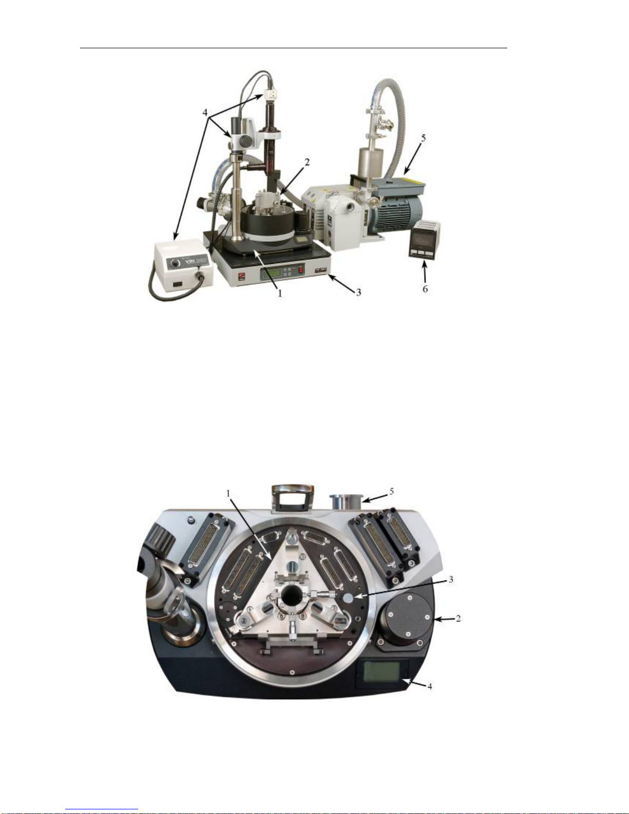
The base module accommodates the stepper motor 2, which provides the approach of the
sample to the probe. There is no function of manual approach of the sample in the vacuum
measurement configuration. Therefore control of the stepper motor is provided only
through the control program Nova.
The LC-display 4 contains information about temperature and humidity inside the vacuum
hood, which is measured by sensor 3.
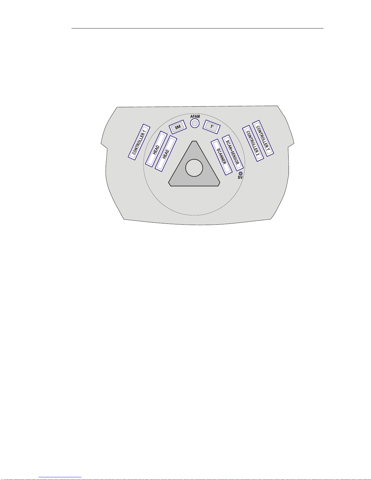
Fig. 1-3 provides a diagram of connectors located in the base unit of the instrument.
Fig. 1-3. Diagram of connectors located in the base unit
There are the following female connectors for connecting devices mounted on the
base unit:
HEAD – for connecting measuring heads.
SCANNER – for connecting scanners. It is used for connecting either
exchangeable scanners or the measuring head scanner.
SCAN+SENSOR – for connecting scanners with built-in sensors. It is used for
connecting either exchangeable scanners or the measuring head
scanner.
Т°– for connecting the heater. It is used to connect heating stages, fluid
cells with heaters etc.
SM – for connecting the stepper motor.
AFAM – for connecting the sample holder to perform the AFAM technique.
BV – bias voltage feed line.
There are the following male connectors for connecting the base unit to the
controllers of the control system:
CONTROLLER 1 – for connecting the PNL controller;
CONTROLLER 2 - for connecting the PNL controller;
CONTROLLER T - for connecting the thermocontroller.
7

NTEGRAAura Probe NanoLaboratory
1.1.2. Exchangeable mount and the positioning device
The exchangeable mount is set into the base unit of the instrument and is fastened with
three screws.
Fig. 1-4 illustrates the positions of the main parts of the exchangeable mount.
Fig. 1-4. Exchangeable mount
1, 2 – measuring head seats; 3 – mirror slots; 4 – positioning device;
5 – measuring head cables holder; 6 - approach system cylinder; 7 – grounding terminal;
8 – fastening screws for the base unit
The exchangeable mount has two types of seats (see positions 1, 2 in Fig. 1-4) used for
mounting measuring heads.
Slots 3 are used to hold an auxiliary mirror during operation with the optical viewing
system.
The positioning device 4 accommodates the sample holder (Fig. 1-5), the scanner or other
device with the sample fastened to it.
Sample
holder
Fig. 1-5. Sample holder installed in the positioning device
The positioning device is installed on the movable cylinder 6 of the approach system
(Fig. 1-4). This makes it possible to translate the sample in the vertical direction.
8

Chapter 1. Basic information
Positioning in the XY plane is performed by means of the micrometer screws 1 (Fig. 1-6)
and the spring seats 2.
Fig. 1-6. Main components of the positioning device
1 – micrometer screws; 2 – spring clips
1.1.3. Vacuum system
The vacuum system contains:
−Vacuum hood;
−Vacuum pump;
−Vacuum gauges with a power supply unit;
−Vacuum components (valves, pipeline, coupling gaskets etc.).
Technical characteristics of the vacuum system:
Residual pressure 5×10⁻² Torr;
Evacuation time 120 min (10-2 Torr).
9

NTEGRAAura Probe NanoLaboratory
Vacuum hood
The vacuum hood (Fig. 1-7) provides enclosed volume for vacuum or controlled gas
environment measurements. In addition, it can be used as a shield against electromagnetic
fields, acoustic noise and temperature variations.
Fig. 1-7. Vacuum hood
There are two viewing windows in the top part of the hood. They are employed by the
optical viewing system to aim laser beam at the cantilever, to select an area of the sample
for measurement and to control the approach and scanning procedures. A viton seal is used
for sealing the hood.
Depending on the vacuum system connection scheme, the hardware set may include a
special adapter flange (Fig. 1-8). This flange is fitted to the base unit and is used for
connecting the pumping system and the pressure gauge. The adapter flange accommodates
flanges for connecting the vacuum pump (position 1 in Fig. 1-8) and the pressure gauge 2.
Fig. 1-8. Adapter flange
1 – flange for the vacuum pump; 2 – flange for the pressure gauge; 3 – viton seal
Viton seal 3 is used for sealing the adapter flange. Surfaces of viton gaskets are greased
with a thin layer of vacuum grease (APIEZON or similar). If required a new layer of
grease should be applied to the hood sealing.
*ATTENTION! Treat the sealing surfaces of the instrument with care. Protect
the viton gasket from accidental damage.
Depending on the instrument configuration, the vacuum system can be assembled
following two variants. These two variants are described in Fig. 1-9 and Fig. 1-10.
10

Chapter 1. Basic information
Variant A
Fig. 1-9 illustrates the vacuum system assembly scheme on variant A. In this case the
vacuum system is connected to the flange located on the rear side of the base unit. Linking
the fore pump line, the pressure gauge 8 and the inlet gas pipe at the same port of the
pipeline is the specifics of variant A.
Fig. 1-9. Vacuum system. Variant А.
1 – vacuum hood; 2 – vacuometer; 3 – vacuum pump; 4 – valve connecting the hood with
the pump; 5 – leak gas valve; 6 – inlet gas valve; 7 – inlet gas valve for the pump; 8 –
pressure gauge; 9, 10 – oil vapor input and output filters; 11 – base unit; 12 – inlet
connecting pipe
The vacuum hood is pumped with a mechanical oil fore pump (see pos. 3) Varian DS-302,
pumping speed 11.6 m3/hour (about 3.2 l/s). To trap oil backstreaming, two filters, input 9,
and output 10, are installed on the pump.
Connecting pipe 12 is used for connecting to the gas pipeline. Leak valve 5 provides
precision delivery of gas.
11

NTEGRAAura Probe NanoLaboratory
12
Variant В
Fig. 1-10 illustrates the vacuum system assembly scheme on variant В. In this case the
adapter flange 13, equipped with connecting flanges KF25 and ISO063, is installed in
between the base unit 11 and the vacuum hood 1. This scheme makes it possible to
separate such functions of the vacuum system as pumping, gas delivery and pressure
control. In addition, the pressure gauge 8 is located at the closest distance to the
measurement area.
Fig. 1-10. Vacuum system. Variant В.
1 –vacuum hood; 2 –vacuometer; 3 –vacuum pump; 4 –valve connecting the hood with
the pump; 5 –leak gas valve; 6 –inlet gas valve; 7 –inlet gas valve for the pump;
8 –pressure gauge; 9, 10 –oil vapor input and output filters; 11 –base unit;
12 –inlet connecting pipe; 13 –adapter flange
1.2. Basic Safety Measures
General Safety Measures
−Ground the instrument before operation!
−Do not disassemble any part of the device. Disassembling of the product is permitted
only to persons certified by NT-MDT.
−Do not connect additional devices to the instrument without prior advice from an
authorized person from NT-MDT.
−This instrument contains precision electro-mechanical parts. Therefore protect it from
mechanical shocks.
−Protect the instrument against the influence of extreme temperature, the direct impact
of sun radiation, and moisture.
−For transport, provide proper packaging for the instrument so as to avoid its damage.

Chapter 1. Basic information
13
Electronics
−To reduce possible influence of power line disturbances on the measurements, we
recommend supplying the instrument units with a surge filter.
−Before operation, set the power switch of the SPM controller to the position
corresponding to value of the local electrical power line (this is only done with the
controller being off!).
−Switch the SPM controller off before connecting/disconnecting its cable connectors.
Disconnecting or connecting the cable connectors during operations may cause damage
to the electronic circuit and disable the instrument. A warning label is attached to the
SPM controller of the instrument (Fig. 1-11).
Fig. 1-11
Laser
−Observe safety measures for operation with devices containing sources of laser
radiation. Do not stare into the beam. A label warning about the presence of laser
radiation is attached to the measuring head. Labels are different for different
wavelength and output power of laser (Fig. 1-12).
Fig. 1-12

NTEGRAAura Probe NanoLaboratory
14
Scanner
−Do not apply to the scanner forces bigger than it is necessary for installation of a probe
or a substrate with a sample. Avoid impacts on the scanner and its lateral displacement.
Remember that thickness of the scanner walls makes only 0.5 mm.
1.3. Operating Conditions
To provide for the normal operation of the device, it is recommended to observe the
following conditions:
−environment temperature: 20 ±5˚C;
−temperature drift less than 1˚C per hour;
−relative humidity less than 80%;
−atmospheric pressure 760 ±30 mm Hg;
−electric mains with 110/220 V (+10% / –15%), 50/60 Hz and grounding;
−the room should be protected from mechanical vibrations and acoustic noises, either
internal or external;
−the table intended for installation of the measuring unit of the instrument must be stable
and, whenever possible, massive.
−vibration criterion VC-C, 12.5 µm/s (one-third octave band criterion);
−the device should be protected from the direct sun radiation impact;
−the measuring unit of the instrument (the base unit with the measuring head) should be
placed on a separate table away from computers and monitors, to eliminate
electromagnetic interference;
The operation of the device is susceptible to heat flows, draughts and sudden alternations
in temperature and humidity.

Chapter 1. Basic information
15
Notes on operating the instrument
−Treat the sealing surfaces of the instrument with care. Protect the viton gasket from
accidental damage.
−If required, a new layer of grease should be applied to the hood sealing.
When mounting the sample, it is not recommended to leave the vacuum hood open for
longer than 1 –2 minutes. Otherwise the longer time of contact with air may result in the
necessity of additional degassing of the instrument.
1.4. Storage and Transport Instructions
−Packaging of the equipment should be performed indoors in a ventilated room at
ambient temperature of 15° С–40 °С and relative humidity at most 80 % with no
corrosive agent in the atmosphere. Storage conditions should comply with the
standard GOST 15150.
−The equipment should be carried by one or several modes of enclosed transport
according to transport regulations applicable to the mode(s) in service.
−Only transportation of the equipment in proper package is permitted to prevent
transportation damage.
−The equipment in its package should be placed and secured in a vehicle in a way
that provides steady position and excludes shocks of the deliverable parts by one
another or by walls of the vehicle.
−Transportation conditions should comply with requirements of the standards
GOST Р52931-2008 and GOST 15150.
−Transportation and storage in regions of the Far North and equated localities should
comply with requirements of the standards GOST Р52931-2008 and GOST 15846.
−Location of the equipment in a warehouse must provide easy access to it and free
space for personnel.
−Devices and their parts should be stored on shelves.
−At least 100 mm distance between the stored parts and walls and ceiling of the
premises should be reserved.
−Distance between the stored parts and heating facilities of the premises should be at
least 0.5 m.

NTEGRAAura Probe NanoLaboratory
2. Setup and installation
2.1. Main procedures
The setup and installation procedure, along with the powering sequence for the instrument,
is described in detail in chapter 3 of Performing measurements manual. This item only
contains a description of the sequence of operations and their specifics related to the
configuration of NTEGRA Aura for measurements in vacuum.
1. Interface board installation.
2. Software installation.
3. Vacuum system installation (see i. 2.2 on page 16).
4. Specifics of the optical viewing system preparation (see i. 2.3 on page 17).
5. Cable connections.
2.2. Vacuum system installation
*ATTENTION! Assembly of the vacuum system is only allowed to authorized
persons of NT-MDT. Assembly performed by users themselves voids warranty
agreements.
Assembly of the vacuum system is performed as described in the schemes provided in
i. 1.1.3 “Vacuum system” on page 9.
The connecting flanges must have no dents and scratches and they must be cleaned. Those
parts of the system installed inside the hood should have no grease and oil residuals.
Grease and oil stains should be wiped off with a cloth soaked in alcohol.
*ATTENTION! Wear special clean gloves both when assembling the vacuum
system and during further operations with it.
16

Chapter 2. Setup and installation
2.3. Specifics of the optical viewing system preparation
Preparation of the optical viewing system for operation is provided in the appendix of
Performing measurements. Nevertheless preparation of the optical viewing system for
operation in vacuum has some specifics.
For the configuration without the adapter flange
When operating with the vacuum system without the adaptor flange (Variant A), an
additional lens 0.5× is installed on the objective of the optical viewing system.
For the configuration with the adapter flange
When operating with the vacuum system equipped with the adaptor flange (Variant B), an
additional lens 0.25× is installed on the objective of the optical viewing system.
In addition, in the case of the configuration with the adapter flange, the microscope stand
of the optical viewing system is used with an extension rod (Fig. 2-1).
Fig. 2-1. Extension rod for the microscope stand
To install the extension rod, perform the following steps:
1. Remove the top clamp for fixing the CCD camera cable (position 1 in Fig. 2-2). Use a
Hex key to undo the fastening screw of the clamp.
Fig. 2-2
1 - top clamp for fixing the CCD camera cable;
2 – fastening screw for angular positioning of the stand; 3 – focusing device
17

NTEGRAAura Probe NanoLaboratory
2. Loose the angular position fastening screw 2 of the stand.
3. Take off the focusing device 3.
4. Install the extension rod in the place of the focusing device so that the extension rod
lug 2 would be above the stand lug 1 (Fig. 2-3).
Fig. 2-3. Installation of the extension rod
1 – stand lug; 2 – extension rod lug; 3 - screws
5. Tighten up the screws 3 of the extension rod.
6. Install the focusing device 2 (Fig. 2-4).
7. Install the clamp for fixing the CCD camera cable 3.
Fig. 2-4. Extension rod installed on the stand of the optical viewing system
1 – extension rod; 2 – focusing device; 3 – cable fixing clamp
18

Chapter 3. Preparation for measurements and operations
3. Preparation for measurements and operations
3.1. Preparation of the instrument and measurements
in air
It is first recommended to prepare the instrument for operating, and then perform test
scanning, in air. The corresponding preparation and measurement procedures for operating
in air are described in detail in Performing measurements.
The difference from operations in air is that there is no function of manual approach of the
sample to the probe in the vacuum measurement configuration. Therefore control on the
vertical translation of the sample is provided only through the control program. Its
description is given below in this item.
Preliminary approach
1. Launch the control program. Turn the SPM controller on.
2. Switch to the tab Approach (button on the panel of main operations).
3. Use the text box Moving for Forward (Fig. 3-1) to set an approximate value for the
distance between the sample and the probe after approach. The value of Moving is
selected so that the corresponding distance would be equal to 0.5÷1 mm.
4. Click the button .
Fig. 3-1. Control panel of the tab Approach
3.2. Pumping
Before pumping, take the sample aside from the probe at a 2÷3 mm distance.
To pump the system, perform the following:
1. Shut the valves 7, 4, 6 (see Fig. 3-2, Fig. 3-3).
2. Turn the vacuometer on.
3. Turn the pump on.
4. After 1÷2 minutes of pumping, open the valve 4.
19

NTEGRAAura Probe NanoLaboratory
5. Continue vacuum forming till the pressure reaches 5×10⁻²÷10-2 Torr. Once the chamber
pressure reaches 5×10⁻² ÷10-2 Torr, measurements can be started.
Fig. 3-2. Vacuum system. Variant А.
1 – vacuum hood; 2 – vacuometer; 3 – pump; 4 – valve connecting the hood with the pump;
5 – leak gas valve; 6 – inlet gas valve; 7 – inlet gas valve for the pump; 8 – pressure gauge;
9, 10 – oil vapor input and output filters; 11 – base unit; 12 – inlet connecting pipe
Fig. 3-3. Vacuum system. Variant В.
1 – vacuum hood; 2 – vacuometer; 3 – pump; 4 – valve connecting the hood with the pump;
5 – leak gas valve; 6 – inlet gas valve; 7 – inlet gas valve for the pump; 8 – pressure gauge;
9, 10 – oil vapor input and output filters; 11 – base unit; 12 – inlet connecting pipe; 13 –
adapter flange
20
Table of contents
Other NT-MDT Laboratory Equipment manuals
Popular Laboratory Equipment manuals by other brands

Radiometer Analytical
Radiometer Analytical TitraLab TIM960 user guide

Reiner
Reiner jetStamp graphic 970 Short Instruction

Zadro Health Soultions
Zadro Health Soultions NANO-UV DUAL SCANNER user manual

Fisher Scientific
Fisher Scientific Fisherbrand Isotemp RT AVCD HPS Advanced Operation manual

Microscan
Microscan QX Hawk user manual

SCHOTT
SCHOTT EasyLED Spotlight Plus user manual