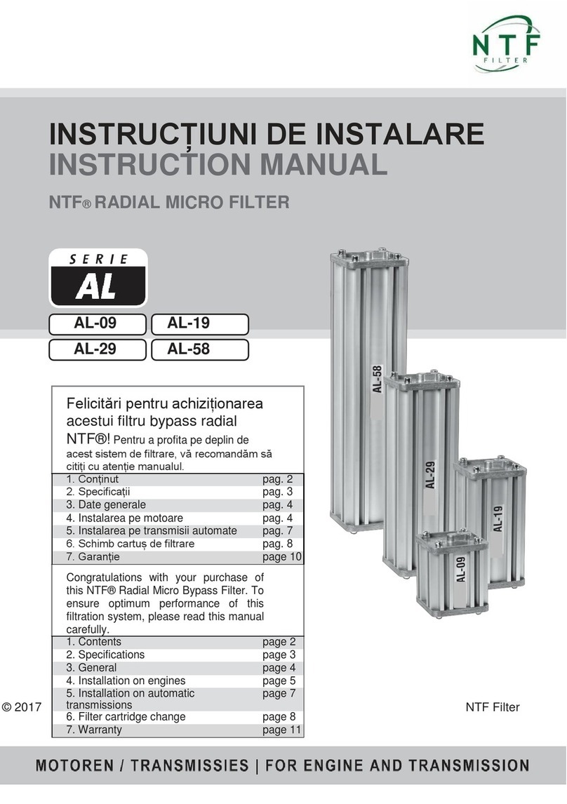
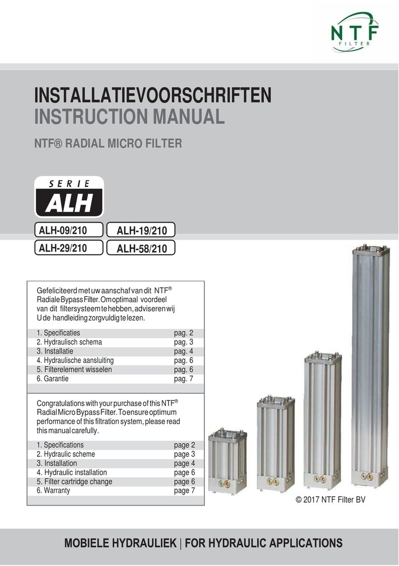
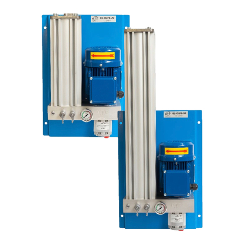
NTF AL Series User manual

MANUAL DE INSTRUCCIONES
INSTRUCTION MANUAL
FILTRO DE ACEITE MICRO BYPASS NTF
®
NTF
®
RADIAL MICRO FILTER
AL-09
AL-29
AL-19
AL-58
© 2017 NTF Filter
Felicidades con su compra de este filtro Micro
Radial Bypass NTF
®
. Para garantizar un
rendimiento óptimo de este sistema de filtración,
por favor lea atentamente este manual.
1. Contenido
pág. 2
2. Especificaciones
pág. 3
3. General
pág. 4
4. Instalación en motores
pág. 4
5. Instalación en transmisiones automáticas
pág. 6
6. Cambio de cartucho
pág. 8
7. Garantiá
Pág. 10
Congratulations with your purchase of this NTF
®
Radial Micro Bypass Filter. To ensure optimum
performance of this filtration system, please read
this manual carefully.
1. Contents
page 2
2. Specifications
page 3
3. General
page 4
4. Installation on engines
page 4
5. Installation on automatic transmissions
page 6
6. Filter cartridge change
page 8
7. Warranty
page 11

2017 NTF
®
FILTER BV www.ntf-filter.com
INST-AL-ES/EN 160817-01
page 2
1.CONTENIDO
/CONTENTS
Qty Pos.
ES
EN
8 A
Perno de tapa de carcasa M8 hexagonal
M8 hexagon cap screws
1 B
Tapa superior carcasa
Top lid
2 C
Sello retenedor
O-ring
1 D
Resorte de presión
Pressure spring
1 E
Anillo de presión
Pressure plate
1 F
Cartucho
Filter cartridge
1 G
Filtro
Filter housing
1 H
Tapa inferior carcasa
Bottom lid
4 I
Anillo de cobre
Copper ring
2 J
Perno banjo
Banjo bolt
2 K
Acople entrada/salida aceite a
manguera
Ring eye
* L
Manguera de presión
Pressure hose
2 N
M 10 Perno
M 10 bolt
4 O
M 10 Tuerca
M 10 nut
2 P
Anillo M 10
M 10 washer
4 Q
M 10 anillo de presión
M 10 spring washer
1 R
Tapa interna de elemento
Inner lid
1 S
Perno banjo con restricción 1,6 mm
Banjo bolt with 1,6 mm restriction
*
ONDERDELEN
NIET
BIJGELEVERD
/
PARTS
NOT
INCLUDED.
A
B
C
D
E
L
K
I
J
S
H
C
F
G
R
NOP
Q

2017 NTF
®
FILTER BV www.ntf-filter.com
INST-AL-ES/EN 160817-01
page 3
2.ESPECIFICATIONES
/SPECIFICATIONS
Tipo de Filtro
Filter type
AL-09
AL-19
AL-29
AL-58
Volumen de aceite/moto
r
Oil volume engine
10 litros
/liter
20 litros
/liter
35 litros
/liter
70 litros
/liter
Volumen de aceite/transmisión
Oil volume transmission
15 litros
/liter
30 litros
/liter
50 litros
/liter
100 litros
/liter
Dimensiones
Dimensions
120x120x140
120x120x230
120x120x350
120x120x700
Peso
Weight
1,5 kg
2,2 kg
3,2 kg
6,4 kg
Volumen
Volume
0,62 litros
/liter
1,13 litros
/liter
1,6 litros
/liter
3,2 litros
/liter
Conexión Entrada/Salida
Connection IN/OUT
M12 X 1,5
M12 X 1,5
M12 X 1,5
M12 X 1,5
Max. Presión
Max. Pressure
7 Bar
7 Bar
7 Bar
7 Bar
Max. Temperatura
Max. temp.
120°C
120°C
120°C
120°C
Tipo de Filtro
Filter type
AL-09
AL-19
AL-29
AL-58
Cartucho
Filter cartridge
F-09
F-19
F-29
F-58
Medio Filtrante
Filter media
celulosa
/cellulose
celulosa
/cellulose
celulosa
/cellulose
celulosa
/cellulose
Dimensiones
Dimensions
Ø78 x 90 mm
Ø78 x 180 mm
Ø78 x 300 mm
Ø78 x 600 mm
Peso
Weight
160 g
300 g
460 g
920 g
Dirección del Flujo
Flow direction
radial
radial
radial
radial
Superficie del Filtro
Filter surface
221 cm
2
442 cm
2
735 cm
2
1470 cm
2
Valor de Retención
Retention value (nom.)
0.5 micron
0.5 micron
0.5 micron
0.5 micron
Eficacia del filtro
Filter efficiency
Beta (ß)
4>10649
Beta (ß)
4>10649
Beta (ß)
4>10649
Beta (ß)
4>10649
Sellos
Seals
Buna NBR
Buna NBR
Buna NBR
Buna NBR
Capacidad de absorción de agua
Water absorption capacity
45 ml H
2
O
90 ml H
2
O
142 ml H
2
O
284 ml H
2
O
Caudal
Flow rate (nom.)
1,6 liter/min
1,6 liter/min
1,6 liter/min
1,6 liter/min

2017 NTF
®
FILTER BV www.ntf-filter.com
INST-AL-ES/EN 160817-01
page 4
3.GENERAL
/GENERAL
-
LosfiltrosNTF
®
seinstalanenbypassalcircuitooriginaldelaceite.Instalarelfiltroenvehículos nuevos
conelprimercambiodeaceite,envehículosusadosalmomentodelcambiodeaceite regular. Cambiar al
mismo tiempo el filtro de flujo principal.
-
Mantener la carcasa y mangueras libres de partes eléctricas,en movimiento, o extremadamente
calientes.
-
Montarelfiltroenunlugarlibredevibraciones.
-
Mantenga las mangueras lomás cortasposible.Sincurvaspuntiagudas,sinextrema tensión.
-
Lacarcasadelfiltrovaaestarcalientealfluiraceiteatravésdelmismo.
-
Instalación y cambio decartucho deben de ser realizados cuando el motor/transmisión estén fríos.
-
Proteja el medio ambiente.
Para la correcta disposición, dejar el cartucho usado en su estación de
servicio o centro local de eliminación de residuos.
-
NTF
®
filterhousingsareinstalledin abypasstotheoriginaloilcircuit.Installthefilteronnew vehicleswith
thefirstoilchange,onusedvehiclesatthetimeofaregularoilchange.Changethe standardmainstream
filteratthesametime.
-
Keep housing and hoses free of electrical conducting,moving,or extreme hot parts.
-
Mountthefilterhousinginaspotfreefromvibrations.
-
Keephosesas short as possible.Nosharpbends,no extremetension.
-
Filterhousingwillbehotasoilisflowingthrough.
-
Installation and cartridge change should take place when the engine / transmission is cold.
-
Protect the environment.
For correct disposal, leave the used cartridge at your service station or the
local waste disposal center.
-
Usando los pernos de la instalación M10 x 50 montar el filtro NTF
®
en la ubicación deseada,
manteniendo en cuenta los siguientes puntos.
-
Montar la carcasa del filtro en un lugar libre de vibraciones tan cerca del motor como sea possible
para mantener las mangueras de entrada y salida lo suficientemente cortas y seguras. Asegurarse
que la parte superior del filtro tenga espacio para el cambio del elemento.
-
NOTA: ¡Nunca instale directamente la carcasa del filtro en el motor!
-
Marcar y perforar la cantidad requerida de agujeros M10, retire la tapa superior de la carcasa del
filtro y deslice los pernos M10 al soporte del casquillo. Ahora ajuste el anillo de presión M10 y
asegure los pernos en la posición requerida a la carcasa del filtro con la tuerca M10. Ahora instale
la carcasa del filtro mediante el uso de los anillos y tuerca M10.
-
Como se trata de una unidad a presión el montaje se puede hacer en cualquier posición. Sin
embargo, el filtro tiene que levantarse verticalmente (entrada en la parte superior) para un cambio
de elemento apropiado.
4.INSTALACIÓNENMOTORES
/INSTALLATION ON ENGINES

2017 NTF
®
FILTER BV www.ntf-filter.com
INST-AL-ES/EN 160817-01
page 5
-
UsingtheinstallationboltsM10x50mounttheNTF
®
bypassfilterhousinginthedesiredlocation,
keepingthefollowingpointsinmind.
-
Mountthefilterhousinginaspotfreefromvibrationsasclosetotheengineaspossibletokeep inlet
andoutlethosesshortandsecure.Makesurethetopsidehas enough clearancefortheelement
change.
-
NOTE: Never installthe filter housing directly on theengine!
-
MarkanddrilltherequiredamountofM10holes,removethetoplidofthefilterhousingandslide the
M10boltsintothesupportsleeves.NowfittheM10springwashers andsecuretheboltsinthe
requiredpositiontothefilterhousingwiththeM10nuts.Nowinstallthefilterhousingbyusingthe
washers and M10nuts.
-
Asthisisapressurizedunitmountingcanbedoneinanyposition.Howeverthefilterhousinghas to
stand up vertically (INLET on bottom side) for convenient element change.
-
Establecer alimentación del aceite. Encuentre un puerto de presión en el lado del bloque
del motor. La mayoría de motores tendrán puertos conectados con 1/8”, 1/4” o 3/8” enchufe
NPT. Si estos no están presentes, busque el indicador de presión de aceite y T en este
puerto. Nunca use la línea de alimentación del aceite de la unidad Turbo.
-
Instale todos los accesorios con hilo desellado de fluidos (cinta de teflón) cuando sea necesario y
evite que este se introduzca en las mangueras y accesorios.
-
La línea de retorno tiene que estar instalada en un puerto
NO PRESURIZADO
.
-
Determinar el punto de retorno del aceite. La mayoría de los motores de combustión tienen puertos
no presurizados en el lado del cárter de o cárter del aceite/pan. Si ninguno de estos
puertos está disponible devolver el aceite a la tapa de válvulas, tubos de llenado de
aceite/pan.
-
Establishoilfeed.Findapressurizedportonthesideoftheengineblock.Mostengines
willhave portspluggedwith1/8”, 1/4” or3/8” NPTplug.Ifthese arenotpresent,locate
theoilpressure gaugeandTintothisport.NeverusetheoilfeedinglineoftheTurbo
unit.
-
Installallfittingswiththreadsealingfluidwherenecessaryandpreventthreadsealingfluidto
enter the hoses and fittings.
-
Thereturnlinehastobeinstalledtoa
NON-PRESSURIZED
port.
-
Determine the oil return point. Most combustion engines have non-pressurized ports on the side of
thecrankcaseoroilsump/pan.Ifnoneoftheseportsareavailablethenreturntheoilto
thevalve cover,fillingtubeoroilpan.
4.1.INSTALACIÓNENBYPASS
/INSTALLATION IN BYPASS
4.INSTALACIÓNENMOTORES
/INSTALLATION ON ENGINES

2017 NTF
®
FILTER BV www.ntf-filter.com
INST-AL-ES/EN 160817-01
page 6
4.2 CONEXIÓN DE LAS MANGUERAS
/ CONNECTING THE HOSES
-
Encamine las mangueras a las puertos de entrada/salida en la parte inferior de la carcasa del filtro.
-
Conecte las mangueras con los accesorios a la carcasa del filtro utilizando los pernos banjo M12 x
1,5 con acoples y las arandelas de cobre.
-
Instale todos los accesorios con hilo desellado de fluidos (cinta de teflón) cuando sea necesario y
evite que este se introduzca en las mangueras y accesorios.
-
Utiliceabrazaderasparagarantizarquetodaslasmangueraspermanezcanlejosdesuperficies
afiladas, eléctricas, o extremadamente calientes.
-
Arranque el motor para comprobar que nohaya fugas. Ejecute el motor hasta que alcance la tem-
peratura de funcionamiento y comprobar el nivel de lubricación del aceite y aumentar la
cantidad necesaria de aceite de lubricación.
-
Compruebe la circulación del aceite controlando la temperatura de la carcasa del filtro.
-
AVISO:Lacarcasadelfiltrovaaestartibiaocalientealfluiraceiteatravésdelmismo.
-
Select a hose compatible to engine/transmission oil. Be aware of the high temperature of the oil.
Route the hoses to the inlet and outlet ports at the bottom of the filter housing.
-
ConnectthehoseswiththefittingstothefilterhousingusingthebanjoboltsM12x1,5withring
eye and copper washers.
-
Installallfittingswiththreadsealingfluidwherenecessaryandpreventthreadsealingfluidto
enter the hoses and fittings.
-
Useziptiestosecureallhosesawayfromsharp,electricalandorhotsurfaces.
-
Start the engine and check for leaks.Run the engine until it reaches operational temperature and
check lubrication oil level and top up the required quantity of lubrication oil.
-
Checkforoilcirculationbycheckingthetemperatureofthefilterhousing.
-
NOTICE: The filter housing and hoses will be warm or hot as oil is flowing through.
4.2. CONEXIÓN DE LAS MANGUERAS
/ CONNECTING THE HOSES

2017 NTF
®
FILTER BV www.ntf-filter.com
INST-AL-ES/EN 160817-01
page 7
-
UsandolospernosdelainstalaciónM10x50montarelfiltroNTF
®
enlaubicacióndeseada, manteniendo
encuenta los siguientes puntos.
-
Montarlacarcasadelfiltroenunlugarlibredevibracionestancercadelrefrigeradordelaceite,o
delospuertosdeentradaysalidadelrefrigeradordelaceiteenlatransmisión,comoseaposible para
mantener las mangueras deentrada y salida losuficientemente cortasy seguras.Asegurarse que la
parte superior del filtro tenga espacio para el cambio del elemento.
-
Marcar y perforar la cantidad requerida de agujeros M10, retire el tapa superior de la carcasa
delfiltroydeslicelospernosM10enelapoyomangas.AhoraajusteelanillodepresiónM10y asegurelos
pernosenelposiciónrequeridaalacarcasadelfiltroconlatuercaM10.Ahorainstale lacarcasadelfiltro
medianteelusodeanillosytuercasM10.
-
Comosetratadeunaunidadapresiónelmontajesepuedehacerencualquierposición.Sin embargo,el
filtro tiene que levantarse verticalmente (entrada en la parte superior) para un cambio deelemento
apropiado).
-
UsingtheinstallationboltsM10x50mounttheNTF
®
bypassfilterhousinginthedesiredlocation, keeping
thefollowingpointsinmind.
-
Mountthefilterhousinginaspotfreefromvibrationsasclosetotheoilcooler,ortheoilcoolerin-
letandoutletportsonthetransmission,aspossibletokeepinletandoutlethosesshortandsecure enough
clearance forthe element change.
-
MarkanddrilltherequiredamountofM10holes,removethetoplidofthefilterhousingandslide
theM10boltsintothesupportsleeves.NowfittheM10springwashersandsecuretheboltsinthe required
positiontothefilterhousingwiththeM10nuts.Nowinstallthefilterhousingbyusingthe washers and M10
nuts.
-
Asthisisapressurizedunitmountingcanbedoneinanyposition.Howeverthefilterhousinghas
to stand up vertically (INLET on bottom-side) for convenient element change.
-
Establecer el alimentador del aceite para la carcasa del filtro mediante la instalación de un
conec tor-Tenlaentradadelalíneadelenfriadordelaceitedelatransmisión.
-
Establecerelretornodelaceitedelacarcasadelfiltromediantelainstalacióndeunconector-T
en la línea de salida
NO PRESURIZADA
del enfriador de la transmisión.
-
EstablishtheoilfeedtothefilterhousingbyinstallinganappropriateT-connectorintheinletline of
the transmission oil cooler.
-
EstablishtheoilreturnfromthefilterhousingbyinstallinganappropriateT-connectorinthe
NON-PRESSURIZED
outlet line of the transmission cooler.
5. INSTALACIÓN EN TRANSMISIONES AUTOMÁTICAS
INSTALLATION ON AUTOMATIC TRANSMISSIONS
5.1.INSTALACIÓNENBYPASS
/INSTALLATION IN BYPASS

2017 NTF
®
FILTER BV www.ntf-filter.com
INST-AL-ES/EN 160817-01
page 8
5.2. CONEXIÓN DE LAS MANGUERAS
/ CONNECTING THE HOSES
-
Encamine las mangueras a los puertos de entrada/salida en la parte inferior de la carcasa del filtro.
-
Conectar las mangueras con los accesorios a la carcasa del filtro utilizando los pernos banjo M12 x
1,5 con acoples y las arandelas de cobre.
-
Instale todos los accesorios con hilo desellado de fluidos (cinta de teflón) cuando sea necesario y
evite que este se introduzca en las mangueras y accesorios.
-
Utiliceabrazaderasparagarantizarquetodaslasmangueraspermanezcanlejosdesuperficies
afiladas, eléctricas, o extremadamente calientes.
-
Arranque el motor para comprobar que nohaya fugas. Ejecute el motor y cambie la transmisión a
través de todos los engranajes hasta que llegue a la temperatura de funcionamiento y
comprobar elniveldelfluidodelatransmisiónautomáticayaumentarlacantidadnecesaria
defluidode transmisión.
-
Comprobar la circulación del aceite controlando la temperatura de la carcasa del filtro.
-
AVISO:Elcarcasadelfiltroylasmanguerasvanaestartibiasocalientesalfluiraceitea
través de las mismas.
-
Select a hose compatible to engine/transmission oil. Be aware of the high temperature of the oil.
Route the hoses to the inlet and outlet ports at the bottom of the filter housing.
-
ConnectthehoseswiththefittingstothefilterhousingusingthebanjoboltsM12x1,5withring
eye and copper washers.
-
Installallfittingswiththreadsealingfluidwherenecessaryandpreventthreadsealingfluidto
enter the hoses and fittings.
-
Useziptiestosecureallhosesawayfromsharp,electrical conducting andorhotsurfaces.
-
Starttheengineandcheckforleaks.Runtheengineandshiftthetransmissionthroughallgears
until it reaches operational temperature and check automatic transmission fluid level
and top up the required quantity of transmission fluid.
-
Checkforoilcirculationbycheckingthetemperatureofthefilterhousing.
-
NOTICE: The filter housing and hoses will be warm or hot as oil is flowing through.
5.2. CONEXIÓN DE LAS MANGUERAS
/ CONNECTING THE HOSES

2017 NTF
®
FILTER BV www.ntf-filter.com
INST-AL-ES/EN 160817-01
page 9
-
Elcambiodecartucho NTF
®
tienequerealizaralmismotiempoquelosintervalosdelcambioestán darde
aceite,talcomosedescribeenelmanual serviciodelconstructordelservicio.
-
Compruebesitieneelelementocorrectoparalacarcasadesufiltro. (ver Especificaciones)
-
Utilice únicamente cartuchos de filtro NTF
®
originales.
-
Utilice únicamente las piezas de repuesto suministradas.
-
Asegúrese que el sistema del filtro este sin presión cuando se sustituya el cartucho.
-
Retirar elcartucho y elsello retenedor (O-ring) del empaque.
-
Retirarlatapadelsistemaysacarlaplacadepresiónconelresorte.
-
Retire el cartucho utilizado y colocarlo en una bolsa de plástico para su eliminación adecuada.
Coloque el nuevo cartucho en el sistema del filtro y la placa de presión con el resorte de nuevo en
ellcartuchodelfiltro. Reemplaceelselloretenedor(O-ring),limpielassuperficiesdeselladoy pongala
tapasobreelsistemadelfiltro.Aprietelospernosdehexágonointeriorconunallavede tuercasdemínimo
9Nmymáximode12Nm.
-
Iniciar elsistema hasta que haya alcanzado sutemperatura de funcionamiento para verificar si
existen fugas.
-
Comprobar el nivel del aceite en el sistema y aumentar la cantidad que sea necesaria.
-
Compruebesiel aceitecorre através del bypass adecuadamente. Silas manguerasy lacarcasa del
filtro se calientan, el filtro funciona correctamente.
-
NTF
®
cartridgechangehastotakeplaceatthesametimeasthestandardoilchange intervals, as
described in the constructors service manual.
-
Check if you have the correct filter element for the filter housing. (see Specifications)
-
Only use original NTF
®
filter cartridges.
-
Only use the supplied spare parts.
-
Ensure that the filter system is pressure-less and cooled when replacing the filter cartridge.
-
Remove the filter cartridge and spare O-ring from the packaging.
-
Removethelidfromthesystemandtakeoutthepressureplatewithspring.
-
Removetheusedfiltercartridgeandplaceitintheplasticbagforproperdisposal.Placethe newfilter
cartridgeinthefiltersystemandplacethepressureplatewithspringbackonthefilter cartridge. Replace
theO-ring,cleanthesealingsurfacesandputthelidbackonthefiltersystem. Tightentheinnerhexagon
boltswithatorqueofminimal9Nmandmaximal12Nm.
-
Start the system until it has reached its operating temperature and check for leakages.
-
Checktheoillevelinthesystemandtopupthenecessaryquantity.
-
Checkiftheoilrunsthroughthebypassproperly.Ifthehosesandthefilterhousingwarmup,the filter
system operates properly.
6. CAMBIO DE CARTUCHO
/ FILTER CARTRIDGE CHANGE

2017 NTF
®
FILTER BV www.ntf-filter.com
INST-AL-ES/EN 160817-01
page 10
1. SISTEMADEFILTRACIÓN
NTF
®
otorga 3 años de garantía limitada en la cubierta del filtro (excluyendo los sellos/caucho) desde la fecha de la
factura. En el supuesto caso de que el comprador encuentra un defecto, lo deberá notificar a su distribuidor de filtros
NTF
®
. Si el defecto está justificado, la cubierta del filtro NTF
®
será reemplazada o reparada de forma gratuita. Cualquier
reclamo sobre la cubierta de los filtros NTF
®
deberá ser dirigido directamente al distribuidor de filtros NTF
®
. El reclamo
debe contener una descripción clara de los resultados obtenidos, incluyendo fotos y especificaciones de la solicitud, junto
con una copia de la factura
2. PROLONGACIÓN DE LA VIDA DEL ACEITE/TIEMPOS DE CA MBIOS DE ACEITE
Cuando el filtro es correctamente instalado, NTF
®
garantiza la operación de filtrado óptimo del filtro NTF
®
y los efectos
positivos para el equipo. El tiempo para realizar los cambios de aceite se pueden prolongar y llegan a darse con el uso
adecuado del sistema NTF
®
No obstante, la condición del aceite, los tiempos en los cambios de aceite depende del
fabricante original del equipo, de las condiciones de operación, selección del aceite/lubricante y el tipo de sistema. Debido
a las condiciones que se encuentran fuera del control de NTF
®
, la prolongación de cualquier cambio de aceite queda a
discreción del cliente. El cliente deberá realizar periódicamente análisis de aceite para asegurar que la condición de éste
es el recomendado en las especificaciones establecidas por el equipo original/fabricante de aceite. Con una solicitud
previa, NTF
®
puede ayudar en esta actividad.
3. GARANTÍA DEL EQUIPO
En el improbable caso de daño material en el equipo, NTF
®
garantizará la totalidad de los costos de
reparación bajo las siguientes condiciones, (Documentación que es total responsabilidad de quien hace
el reclamo):
• Si al equipo se le ha dado un apropiado mantenimiento y trabaja en buen estado al momento de la instalación, lo
cual puede ser demostrado mediante las copias del historial del mantenimiento y reparación de los equipos.
• Si el filtro NTF
®
fue instalado por un mecánico certificado.
• El usuario debe demostrar que el daño en el dispositivo se debe al mal funcionamiento de un
sistema de filtro NTF
®
, con una correcta instalación y habiéndolo proporcionado el uso adecuado.
• El cliente debe demostrar con datos reales o con un programa de cambios de aceite con períodos prolongados
(datos históricos) que el aceite o lubricante en el dispositivo estaba dentro de las especificaciones de uso apropiado
al momento de producirse la falla.
4. RESPONSABILIDAD
La garantía y cobertura de NTF
®
arriba mencionada no se extiende más allá (como consecuencia de)
defectos en el filtro NTF
®
.Daños como resultado por terceras causas así como errores durante la
instalación, montaje incorrecto en el circuito de lubricación, o por error en el montaje del dispositivo o
mangueras, no son cubiertos ni por esta garantía ni por la cobertura de productos NTF
®
.
Con respecto al montaje de piezas proporcionadas por NTF
®
, la garantía aplicable es aquella proporcionada por el
productor/ proveedor de las partes instaladas, la cual es traspasada por NTF
®
al cliente. La responsabilidad es limitada al
monto mencionado en la póliza de seguro sobre coberturas de riesgo que NTF
®
ha concluido con N.V. Interpolis. Ningún
reclamo puede exceder los €2’500.000,00 (Dos millones quinientos mil euros). El monto máximo de cobertura anual por
daños no deberá exceder los €5´000.000,00 (cinco millones de euros).
5. POLÍTICA SOBRE LA ANULACIÓN DE GARANTÍA
La garantía no se aplica (es anulada) por el usuario, siempre y cuando:
• El filtro NTF
®
es manipulado sin el debido cuidado o en contradicción con las instrucciones de uso de los filtros
NTF
®
o si el filtro es usado con otro propósito que no sea el especificado.
•
Se hayan usado cartuchos genéricos y no los originales de NTF
®.
• Una factura de compra con fecha no válida/certificado de garantía no es aplicable.
• Si el defecto o daño es el resultado de un desastre natural, por accidente, mal uso, o incorrecto
uso, o por alguna causa externa, por lo que NTF
®
no es responsable.
En caso de disputa legal se aplica la legislación Holandesa.
7. GARANTÍA
/ WARRANTY

2017 NTF
®
FILTER BV www.ntf-filter.com
INST-AL-ES/EN 160817-01
page 11
1.
FILTER SYSTEM
NTF
®
grants a 3-year limited warranty on the NTF® filter housing (excluding the accompanying o-rings) from the date of
invoice. In the unlikely event that the purchaser finds a defect, the purchaser must notify their NTF
®
dealer. If the defect is
justified, the NTF
®
filter housing will be replaced or repaired free of charge. Any claims to NTF
®
filter housings should be
addressed directly to your NTF® point of contact. A claim should contain a clear description of the findings, including
pictures and specifications of the application, along with a copy of the invoice.
2.
EXTENDED OIL LIFE / DRAIN INTERVALS
When properly installed, NTF
®
guarantees the effective filtering operation of the NTF
®
filter and its positive effects for the
equipment. Extended oil drain intervals are achievable with the proper use of the NTF
®
system. However, the condition of
the oil and the oil change intervals are also dependent upon the original equipment manufacturer, operating conditions,
selection of lube/oil, and system type. Due to conditions out of the control of NTF
®
, the length of any extended drain
interval is at the discretion of the customer. The customer should perform regular oil analysis to ensure that the condition
of the oil is within the recommended specifications as set by the original equipment/oil manufacturer. Upon request, NTF
®
can aid in this activity.
3.
EQUIPMENT WARRANTY
In the unlikely event of material damage to the equipment, NTF
®
warrants the entire cost of repair under the following
conditions (Documentation of which is the full responsibility of the claimant):
•
The equipment is well maintained and worked properly at the moment of installation which can be proven by copies of
the maintenance and repair history of the equipment.
•
The NTF
®
filter is installed by a certified mechanic.
•
The user must demonstrate the device damage is due to the malfunction of a properly installed and properly used
NTF
®
filter system.
•
The customer must demonstrate from actual data or from a documented extended drain interval program (historical
data) that the oil or lube fluid in the device was within the proper usage specifications at time of failure.
4.
LIABILITY
The above mentioned warranty and NTF’s liability does not extend beyond (the consequences of) defects in the NTF
®
filter. Damage as a result of other means or caused by third parties, such as by errors during installation, by incorrect
mounting onto the oil circuit or by mounting devices or hoses are not covered, neither by this warranty nor by NTF’s
product liability. With regard to mounting pieces supplied by NTF
®
the warranty applicable is the warranty of the
suppliers/producers of the mounting pieces which is passed on by NTF® to its customers. Liabilities are limited to the
amounts mentioned in the insurance policy for liability risks that NTF® has concluded with N.V. Interpolis. No claim shall
exceed Euro 2.500.000. The maximum annual amount of damages covered shall not exceed Euro 5.000.000.
5.
BREACH OF WARRANTY POLICY
The warranty is non-applicable (breached) by user if and when:
•
The NTF
®
filter is handled without due care or in contradiction with the instructions for use, or if used for purposes
other than its suggested purpose.
•
Cartridges other than original NTF® filter cartridges have been applied.
•
No valid dated purchase invoice/warranty certificate can be produced.
•
The defect and/or the damage is a result of a natural disaster, accident, misuse, incorrect use or any other outside
cause for which NTF
®
is not liable.
In case of disputes Dutch law is applicable.
7. GARANTÍA
/ WARRANTY
Other manuals for AL Series
1
This manual suits for next models
4
Table of contents
Other NTF Water Filtration System manuals