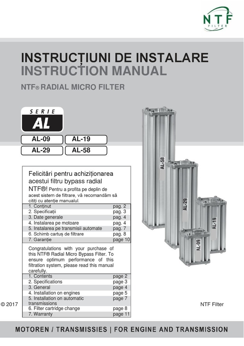
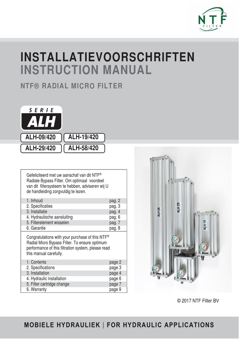
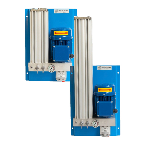
NTF ALH Series User manual

INSTALLATIEVOORSCHRIFTEN
INSTRUCTION MANUAL
NTF® RADIAL MICRO FILTER
ALH-09/210
ALH-29/210
ALH-19/210
ALH-58/210
© 2017 NTF Filter BV
Gefeliciteerdmetuwaanschafvandit NTF
®
RadialeBypassFilter.Omoptimaal voordeel
van
dit filtersysteemtehebben,adviserenwij
Ude
handleidingzorgvuldigtelezen.
1. Specificaties
pag. 2
2. Hydraulisch schema
pag. 3
3. Installatie
pag. 4
4. Hydraulische aansluiting
pag. 6
5. Filterelement wisselen
pag. 6
6. Garantie
pag. 7
CongratulationswithyourpurchaseofthisNTF
®
RadialMicroBypassFilter.Toensureoptimum
performanceofthisfiltrationsystem,pleaseread
thismanualcarefully.
1. Specifications
page 2
2. Hydraulic scheme
page 3
3. Installation
page 4
4. Hydraulic installation
page 6
5. Filter cartridge change
page 6
6. Warranty
page 7

3
Filter type
Filter type
ALH-09/210
ALH-19/210
ALH-29/210
ALH-58/210
Materiaal behuizing
Material housing
Aluminium
Geanodiseerd
Aluminium
anodized
Aluminium
Geanodiseerd
Aluminium
anodized
Afmetingen (hxbxd)
Dimensions (mm)
120x120x180
120x120x280
120x120x380
110x145x780
Gewicht
Weight
2,2 kg
3,4 kg
4,6 kg
7,3 kg
Tankinhoud (richtlijn)
Sump volume in liters
225 liter
450 liter
750 liter
1500 liter
Aansluiting retour
Connection OUT
¼ BSP inw.
¼ BSP inw.
¼ BSP inw.
¼ BSP inw.
Min./Max werkdruk
str. regelventiel
Operating Pressure Min./Max.
10 / 210 Bar
10 / 210 Bar
10 / 210 Bar
10 / 210 Bar
Bypass setting
Bypass setting
5,5 Bar
5,5 Bar
5,5 Bar
5,5 Bar
Max. temperatuur
Max. temp.
100°C
100°C
100°C
100°C
Max. viscositeit
Maximum viscosity
180 cSt
180 cSt
180 cSt
180 cSt
Indicator
Indicator
manometer
manometer
manometer
manometer
Aansluiting perszijde
Connection Pressure
¼ BSP inw.
¼ BSP inw.
¼ BSP inw.
¼ BSP inw.
Diameter persslang / retourslang
I.D. Pressure hose / diameter return hose
10 / 12 mm
10 / 12 mm
10 / 12 mm
10 / 12 mm
Filterpatroon
Filter cartridge
F-09
F-19
F-29
F-58
Filtermedium
Filter media
cellulose
cellulose
Cellulose
cellulose
Afmetingen
Dimensions
Ø78 x 90 mm
Ø78 x 180 mm
Ø78 x 300 mm
Ø78 x 600 mm
Gewicht
Weight
160 g
300 g
460 g
920 g
Doorstroming
Flow direction
radiaal
/radial
radiaal
/radial
radiaal
/radial
radiaal
/radial
Filteroppervlak
Filter surface
221 cm
2
442 cm
2
735 cm
2
1470 cm
2
Filter fijnheid
Retention value (nom.)
0.5 micron
0.5 micron
0.5 micron
0.5 micron
Filter efficientie
Filter efficiency
Beta (ß)
4>10649
Beta (ß)
4>10649
Beta (ß)
4>10649
Beta (ß)
4>10649
Afdichtingen
Seals
Buna NBR
Buna NBR
Buna NBR
Buna NBR
Nominale flow
Nominal flow
1,0 ltr/min
1,5 ltr/min
2,1 ltr/min
4,2 ltr/min
Monitor connections
Connections monitor
N.A.
N.A.
N.A.
N.A.
1. SPECIFICATIES
/ SPECIFICATIONS

© 2017 NTF
®
FILTER BV www.ntf-filter.com page 4
-De filterunit wordt aangeleverd met 2 “P” (druk) en 2 “T” (retour) aansluitingen. De
onderzijde is afgedicht met kunststof doppen, de zij-aansluitingen “P” en “T” zijn
afgedopt met stalen pluggen. Indien de zij-aansluitingen worden gebruikt, de
onderpoorten afdoppen met metalenpluggen!
-Maak gebruik van de bijgeleverde 10 x 50 bouten om het NTF Bypass filter op de
gewenste positie te monteren. Let hierbij op hetvolgende:
-Monteer het filterhuis op een plaats vrij van trillingen. Houdt de slangen zo kort
mogelijk. Niet scherp buigen, niet strak spannen. Let erop dat er boven het
filterhuis genoeg ruimte is om het patroon te wisselen
-Houdt er bij installatie rekening mee, dat de manometer (optie) goed af te lezen
is. De manometer kan op de “M” poort aan de onderkant of op de “M” poort aan
de zijkant wordengemonteerd.
-De unit dient dusdanig geïnstalleerd te worden, dat er voldoende toegang is tot
de minimess meetpunten (optie) voor gebruikmaking van de CM20 deeltjesteller.
De aanvoerleiding van de CM20 (rood) dient te worden aangesloten op de vrije
“M” poort. De retourleiding van de CM20 (geel) dient te worden aangesloten op
de “T” poort.
-The filter system has been equipped with “P” (pressure) en 2 “T” (return)
connections. The bottom connections have been sealed with plastic caps. The
side connections “P” en “T” have been sealed with steel caps. When using
these, assure that the steel caps are used to seal the connections on the bottom.
-Mount the filter system at the desired location using the supplied M10 x 50
hexagon bolts, taking the following in consideration:
-Mount the filter system on a spot free from vibrations. Keep hoses as short as
possible. Do not bend or tense hoses. Assure there is enough space to be able
to change the filter cartridge.
-Assure that the pressure gauge is properly legible. The pressure gauge may be
installed on either the side or bottom “M” connection.
-The filter system should be installed in such a manner that enough space is
available to connect the CM20 oil analysis equipment to the minimess sample
connections (optional). The feed line (red) of the CM20 should be connected to
available “M” connection. The return line (yellow) should be connected to the “T”
connection.
3. INSTALLATIE
/ INSTALLATION

© 2017 NTF
®
FILTER BV www.ntf-filter.com page 5
-Monteer op het aluminium blok eerst een inschroefnippel, monteer daar de slang
of leiding op.
-De toevoerdruk op de “P” aansluiting (1/4” BSP) dient minimaal 10 bar en mag
maximaal 200 Bar zijn. Selecteer een aanvoerpunt met een constante druk, bij
voorkeur de vulpomp van het systeem.
-De “T” aansluiting (1/4” BSP) dient drukloos met de tank verbonden te worden.
Maak daarbij geen gebruik van bestaande retourleidingen. Een overdruk van
maximaal 1 Bar in de tank is geen bezwaar. MONTEER GEEN RESTRICTIES
IN DETANKLEIDING!
-Gebruik voor de persleiding hydrauliekslang (diameter 3/8” BSP) welke geschikt
is voor een werkdruk van minimaal 250 bar voorzien van bijbehorende
slangkoppelingen. Geen lage drukslang toe tepassen.
-Gebruik voor de retour ook een 2 staalinlage hydrauliekslang (diameter 1/2”
BSP) voorzien van bijbehorende slangkoppelingen. Diameter 1/2 "BSP
toepassen om zo min mogelijk retourdruk te creëren. Wij adviseren geen lage
drukslang toe te passen. Houd de retourleiding zo kort mogelijk!
-Gebruik bij de installatie de juiste hydrauliek koppelingen. Gebruik onder geen
enkele voorwaarde Loctite of tape.
-First screw a connector into the aluminium manifold then connect the hose to that
connector.
-The pressure on the “P” connection (1/4” BSP) should have a minimum of 10 bar
and a maximum of 200 bar. Select a feed point with a constant pressure,
preferably the filling pipe of the system.
-The return hose on the “T” connection (1/4” BSP) must be connected to the tank
without pressure. Do not use existing return lines. A maximum pressure of 1 Bar
in the tank is allowed. DO NOT MOUNT ANY RESTRICTIONS IN THE RETURN
LINE!
-Use appropriate high pressure hydraulic hoses equipped with proper connections
to establish the pressure line (diameter 3/8” BSP). Do not use hoses for low-
pressure applications.
-To establish the return line use double steel-layered hydraulic hoses (diameter
1/2” BSP) equiped with the appropriate connectors . To ensure minimal return
pressure use a return hose with 1/2 "BSP diameter. Do not use hoses for
low-pressure applications. Keep the return line as short as possible!
-Use proper hydraulic connector materials. Do not use tape or sealingliquid!
4. HYDRAULISCHE AANSLUITING
/ HYDRAULIC INSTALLATION

© 2017 NTF
®
FILTER BV www.ntf-filter.com page 6
-
Wisselelementenbijeendrukoverhetfiltervan5 Bar(bijwerktemperatuur!)oftenminsteelke
6maanden.
-
Controleer of er een overdruk op de tank staat.Laat dedruk zonodig aflopen.
-
Zorgeraltijdvoordatbijhetwisselenvanelementendefilterunitdrukloosis.
-
Haal het vervangingspatroon en de O-ring uit de plastic zak.
-
Schroef het bovendeksel van het filterhuis en verwijder de drukdeksel met de veer.
-
Verwijderhetgebruiktepatroonenstopdezeindeplasticzak.Denieuwepatrooninhethuis
plaatsen en stevig op de bodemplaat drukken. Plaats de drukplaat met veer terug op het nieuwe
filterpatroon.
-
Verwissel deO-ring, reinig de afdichtvlakken en schroef het bovendeksel weer stevig vast. Zet de
inbusbouten vast met een aanhaalmoment van minimaal 9 Nm en maximaal 12 Nm.
-
Start het systeem totdat deze op bedrijfstemperatuur is en controleer op lekkage.
-
Controleerook het oliepeil.Olienaar behoefte bijvullen.
-
Controleer of de olie goed door de bypass stroomt.Als het huis ende slangen warm worden,
functioneert het systeem goed.
-
Filter cartridge needs to be replaced when the pressure over the filter at operating temperature is
5 Barorevery6months.
-
Check for pressure on the tank. Relief the pressure of the system when necessary.
-
Ensure that the filter system is pressureless when replacing the filter cartridge.
-
Remove the filter cartridge and spare O-ring from the packaging.
-
Removethelidfromthesystemandtakeoutthepressureplatewithspring.
-
Removetheusedfiltercartridgeandplaceitintheplasticbagforproperdisposal.Placethe
newfiltercartridgeinthefiltersystemandplacethepressureplatewithspringbackonthefilter
cartridge. ReplacetheO-ring,cleanthesealingsurfacesandputthelidbackonthefiltersystem.
Tightentheinnerhexagonboltswithatorqueofminimal9Nmandmaximal12Nm.
-
Start the system until it has reached its operating temperature and check for leakages.
-
Checktheoillevelinthesystemandtopupthenecessaryquantity.
-
Checkiftheoilrunsthroughthebypassproperly.Ifthehosesandthefilterhousingwarmup,the
filter system operates properly.
5. FILTERELEMENT WISSELEN
/ CARTRIDGE CHANGE

© 2017 NTF
®
FILTER BV www.ntf-filter.com page 7
1. FILTERSYSTEEM
Op deNTF
®
filterhuizen (niet debijbehorende O-ringen en appendages) geven wij een materiaalgaran-
tievan3jaarnafactuurdatum.Indiengebrekenwordengeconstateerd,dientdekoperonverwijldzijn
NTF
®
dealeropdehoogtetestellen.Alsdegebrekengegrondzijn,zalhetNTF
®
filtersysteemkoste-
loos worden gerepareerd dan wel vervangen.Voor het in behandeling nemen van een claim moet met
het filter ook een duidelijke omschrijving van de bevindingen (indien mogelijk met foto’s), specificaties
van de toepassing en een kopie van de factuur worden meegestuurd.
2. LANGEREOLIESTANDTIJD
Wanneer juist geïnstalleerd, garandeert NTF
®
een probleemloze werking van het filter systeem en de
positieveeffectenvoorhetsysteemwaarhetfilteropgeïnstalleerdis.Doorjuistetoepassingvanhet
NTF® systeem kunnen langere olie standtijden worden bereikt. De conditie van de olie en de standtijd
van de olie is evenwel mede afhankelijk van het advies van de fabrikant,bedrijfsomstandigheden, type
olieenhetsysteemwaarophetfilterwordtgemonteerd.Alsgevolgvandezevoorwaardendiebuiten
de invloed van NTF
®
vallen, is het verlengen van de olie standtijd de volledige verantwoording van de
gebruiker.De gebruiker dient zich door middel van olieanalyses regelmatig ervan te verzekeren dat de
olie nog in goede conditie is. Op aanvraag kan NTF
®
hierbij assisteren.
3. GARANTIE VAN UW INSTALLATIE / MACHINE
In het geval van materiële schade aan de installatie/machine, vergoedt NTF
®
de kosten voor reparatie
met inachtneming van de volgende condities (De documentatie van de schade is de verantwoordelijk-
heidvan degebruiker):
•
De installatie/machine is goed onderhouden en werkte naar behoren op het moment van instal-
latie; dit moet aantoonbaar kunnen worden gemaakt door middel van onderhoudspapieren van
hiertoe gecertificeerdebedrijven.
•
Het NTF
®
filter dient geïnstalleerd te zijn door een hiertoe gecertificeerde bedrijf.
•
De gebruiker moet aantonen dat de schade is ontstaan door toedoen van het NTF
®
filter,welke
op juiste wijze is geïnstalleerd en toegepast.
•
De gebruiker moet met historische data van olieanalyses kunnen aantonen dat de olie in de instal-
latie/machine ten tijde van de opgetreden schade binnen de vereiste specificaties viel.
4.
AANSPRAKELIJKHEID
De bovengenoemde garantie en de aansprakelijk van NTF
®
zullen nimmer verder strekken dan voor
(gevolgen van) gebreken aan het NTF
®
filter.Schaden die anderszins of door derden ontstaan,zoals
door montagefouten bij de installatie, door onjuiste aansluiting op het oliecircuit of door aansluitdelen
of slangen,vallen niet onder deze garantie,noch onder onze productaansprakelijkheid. Voor het door
NTF
®
geleverdemontagemateriaal geldt degarantie van deleveranciers/producenten van deze mate-
rialen,welke wij aan onze klanten doorgeven.Verplichtingen worden beperkt tot de bedragen vermeld
in de verzekering voor de aansprakelijkheid van risico’s die NTF
®
heeft gesloten met NV Interpolis.Per
claim zal maximaal 2.500.000 Euro worden uitgekeerd.
Het maximale bedrag van de schadevergoeding per jaar zal het bedrag van Euro 5.000.000 niet overstijgen.
6. GARANTIE
/ WARRANTY

© 2017 NTF
®
FILTER BV www.ntf-filter.com page 8
5. SCHENDINGVANHET GARANTIEBELEID
De garantie is niet van toepassing (geschonden) door de gebruiker indien en wanneer:
•
Het NTF
®
filter onzorgvuldig of in strijd met de aanwijzingen en/of de gebruiksaanwijzingen is
behandeld, dan wel is aangewend voor niet geëigende doeleinden.
•
Geen originele NTF
®
filterelementenzijn toegepast.
•
Geengeldigegedateerdeaankoopfactuurkanwordenoverlegd.
•
Het defect en/of de schade is ontstaan door een natuurlijke ramp,ongeval, misbruik, verkeerd
gebruik of enige andere van buiten komende oorzaak.
In geval van geschillen is Nederlands recht van toepassing.
1.
FILTER SYSTEM
NTF
®
grants a 3-year limited warranty on the NTF
®
filter housing (excluding the accompanying
o-rings)fromthedateofinvoice.Intheunlikelyeventthatthepurchaserfindsadefect,thepurchaser
mustnotifytheirNTF
®
dealer.Ifthedefectisjustified,theNTF®filterhousingwillbereplacedor
repairedfreeofcharge.AnyclaimstoNTF
®
filterhousingsshouldbeaddresseddirectlytoyourNTF
®
pointofcontact.Aclaimshouldcontainacleardescriptionofthefindings,includingpicturesandspecifi-
cationsoftheapplication,alongwithacopyoftheinvoice.
2. EXTENDED OIL LIFE /DRAIN INTERVALS
Whenproperlyinstalled,NTF
®
guaranteestheeffectivefilteringoperationoftheNTF
®
filterandits
positive effects for the equipment. Extended oil drain intervals are achievable with the proper use of the
NTF
®
system.However,theconditionoftheoilandtheoilchangeintervalsarealsodependentupon
the original equipment manufacturer, operating conditions, selection of lube/oil, and system type. Due
toconditionsoutofthecontrolofNTF
®
,thelengthofanyextendeddrainintervalisatthediscretionof
thecustomer.Thecustomershouldperformregularoilanalysistoensurethattheconditionoftheoilis
within the recommended specifications as set by the original equipment/oil manufacturer. Upon request,
NTF
®
can aid in this activity.
3. EQUIPMENT WARRANTY
Intheunlikelyeventofmaterialdamagetotheequipment,NTF
®
warrantstheentirecostofrepair
under the following conditions (Documentation of which is the full responsibility of the claimant):
•
Theequipmentiswellmaintainedandworkedproperlyatthemomentofinstallationwhichcanbe
proven by copies of the maintenance and repair history of the equipment.
•
TheNTF
®
filterisinstalledbyacertifiedmechanic.
•
Theusermustdemonstratethedevicedamageisduetothemalfunctionofaproperlyinstalled
and properly used NTF
®
filtersystem.
•
Thecustomermustdemonstratefromactualdataorfromadocumentedextendeddraininterval
program(historicaldata)thattheoilorlubefluidinthedevicewaswithintheproperusagespecifi-
cationsattimeoffailure.
6. GARANTIE
/ WARRANTY

© 2017 NTF
®
FILTER BV www.ntf-filter.com page 9
4.
LIABILITY
Theabovementionedwarranty andNTF’s liabilitydoesnot extendbeyond(theconsequencesof) defects
intheNTF®filter.Damageasaresultofothermeansorcausedbythirdparties,suchasbyerrors
duringinstallation,byincorrectmountingontotheoilcircuitorbymountingdevicesorhosesarenot
covered, neither by this warranty nor by NTF’s product liability.With regard to mounting pieces supplied
byNTF
®
thewarrantyapplicableisthewarrantyofthesuppliers/producersofthemountingpieces
whichispassedonbyNTF
®
toitscustomers.Liabilitiesarelimitedtotheamountsmentionedinthe
insurancepolicyforliabilityrisksthatNTF®hasconcludedwithN.V.Interpolis.Noclaimshallexceed
Euro 2.500.000. The maximum annual amount of damages covered shall not exceed Euro 5.000.000.
5.
BREACH OF WARRANTY POLICY
The warranty is non-applicable (breached) by user if and when:
•
TheNTF
®
filterishandledwithoutduecareorincontradictionwiththeinstructionsforuse,orif
used for purposes other than its suggested purpose.
•
CartridgesotherthanoriginalNTF
®
filtercartridgeshavebeenapplied.
•
TheNTF®filterisreinstalledontoaninstallation(engine,transmission,hydraulicapplication)other
than indicated on the warranty certificate.
•
Novaliddatedpurchaseinvoice/warrantycertificatecanbeproduced.
•
The defect and/or the damage is a result of a natural disaster, accident, misuse, incorrect use or
any other outside cause for which NTF
®
is not liable.
In case of disputes Dutch law is applicable.
6. GARANTIE
/ WARRANTY
Other manuals for ALH Series
1
This manual suits for next models
4
Table of contents
Other NTF Water Filtration System manuals
Popular Water Filtration System manuals by other brands

Pahlen
Pahlen Autodos M1 user manual

Bestway
Bestway Flowclear 58397 owner's manual

AQVA Finland
AQVA Finland AQVA GLASS General instructions

Watts Premier
Watts Premier WP-5 Installation, operation and maintanance manual

Honeywell Home
Honeywell Home F78TS installation instructions

Oase
Oase FiltoClear 5000 operating instructions

Miele
Miele FFK APCL Fitting instructions

Air Water Life
Air Water Life AQUA-IONIZER DELUXE 7.5 owner's manual

Dongtuo
Dongtuo KC-88 manual

Sartorius
Sartorius arium mini plus operating instructions

BSVILLAGE
BSVILLAGE Azuro 2m3/h Installation, assembly and operation manual

Graco
Graco 210-091 Instructions-parts list