NTF OLFS Series User manual

INSTRUCTION MANUAL
NTF
®
RADIAL MICRO FILTER
© 2017 NTF Filter
Congratulations with your purchase of this NTF® Radial
Micro Offline Filter. To ensure optimum performance of
this filtration system, please read this manual carefully.
1. Introduction
page 2
2. General description
page 2
3. Purpose
page 2
4. Safety regulations, risks and warnings
page 2
5. Operating instructions
page 3
6. Transport, storage and disposal
page 3
7. Installation and assembly
page 4
8. Maintenance instructions
page 5
9. Warranty
page 6
10. Hydraulic scheme
page 7
11. Technical specifications filter system
page 8
12. Technical specifications gear pump
page 9
13. Technical specifications motor
page 10
14. EU declaration of conformity
page 28
OLFS-58/1
OLFS-29/1
FOR INDUSTRIAL HYDRAULIC APPLICATIONS

© 2017 NTF
®
FILTER BV www.ntf-filter.com
INST-OLFS1-EN 100718-03
page
2
1. INTRODUCTION
2. GENERAL DESCRIPTION
3. PURPOSE
4. SAFETY REGULATIONS, RISKS AND WARNINGS
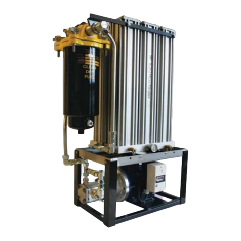
This NTF (OLFS) off-line filtration system can be applied for the re-circulation of fluids in any hydraulic,
lubrication, transmission and fuel system. The unit has been fitted with a dedicated motor and pump, thus
ensuring that system pressure and specifications stay within factory prescribed limits. The purpose of the
OLFS is to recirculate the fluid by pumping it from a reservoir or reservoir through the filter and return it to the
reservoir. Cleaner oil leads to less malfunctions and cost savings.
The OLFS has been modulary fitted on a manifold, in which all oil channels have been integrated, thereby
minimizing the risk of oil leaks. The main advantage of the OLFS unit is that the filtration process takes place
under constant flow and pressure. Because of this the efficiency is 10 times higher than of any in-line filter
system. The results are:
-
Cleaner oil
-
Less malfunctions of the system the OLFS is fitted on.
-
Less wear of the system the OLFS is fitted on.
-
Prolonged life time of the system the OLFS is fitted on.
-
Less oil consumption, better for the environment.
The OLFS is marked with
The OLFS has been constructed according to CE norm machinery directive
This OLFS filter system is specially designed for filtration of hydraulic and lubrication oil reservoirs. It can also
be applied to fuel systems. When filtering fuel it is highly recommended to install a water separator in the
suction line. As NTF filter cartridges are hygroscopic the water content in the fuel may cause the elements to
saturate prematurely.
Please keep the following in mind when installing the OLFS unit:
-
Before assembling, connecting or servicing the OLFS unit, make sure that the application, on which
the OLFS will be installed is safe to work on. If necessary, shut off electricity. Make sure that there is
no oil pressure on the oil lines. If there is pressure, bring it down to 0 Bar.
-
Use the proper hoses for the application (hydraulic or fuel).
Do not use hoses for low-pressure
applications.
-
Make sure that the return line from the OLFS to the tank has no pressure. Do
not use existing
return lines.
-
Use the proper connector materials for the application (hydraulic or fuel). Do not use tape or sealing
liquid!
-
When starting up the system, make sure that the motor is rotating in the proper direction (clockwise).
-
When replacing the filter elements or when spillage occurs, use the personal safety equipment, as
prescribed in the Material Safety Data Sheet of the fluid.

© 2017 NTF
®
FILTER BV www.ntf-filter.com
INST-OLFS1-EN 100718-03
page
3
4. SAFETY REGULATIONS, RISKS AND WARNINGS
5. OPERATING INSTRUCTIONS (INCLUDING MOTOR)
6. TRANSPORT, STORAGE AND DISPOSAL
Installation of this unit is only allowed to certified professionals engineers. In
case of warranty claims certificates will be requested
The unit must be properly grounded to avoid any static electricity
Before switching on the unit ALWAYS check that there are no restrictions in
the suction and return line. In case valves are installed in suction and or return
line of the filter unit these valves should be opened before the unit is switched
on.
When replacing the filter elements or when spillage occurs, use the personal
safety equipment, as prescribed in the Material Safety Data Sheet. Check also
personal safety regulations at site.
The filter is functional when the motor is running. Installation should be done by certified electrical engineers.
The user is responsible for the proper electrical wiring and installation of the filter unit. User must determine the
appropriate guidelines as to when and how switch the unit to on and off. Additional information with regard to
this point can be found under no.13
“
Technical specifications motor
”
This OLFS-unit has been carefully packed to avoid damage during normal transport. Should your OLFS unit
arrive damaged, please take pictures of the occured damages and send these with a description to your NTF
®
dealer, so the damaged unit can quickly be replaced. There are no further special requirements for transport or
storage.
When the OLFS unit or filter element is disposed off, the local regulations for disposing chemical waste should
be taken into account.

© 2017 NTF
®
FILTER BV www.ntf-filter.com
INST-OLFS1-EN 100718-03
page
4
7. INSTALLATION AND ASSEMBLY
-
Before assembling and connecting the OLFS unit, make sure that the machine, on which the OLFS
will be installed is safe to work on. If necessary, shut down electricity. Make sure that there is no
system pressure. If there is pressure, bring it down to 0 Bar.
-
Mount the filter system on a vibration free spot.
-
Keep hoses as short as possible. Do not bend or tense hoses.
-
Make sure there is enough space after installation to be to have easy access for cartridge changes.
-
Assure that the pressure gauge is properly accessible.
-
The filter system should be installed in such a manner that enough space is available to connect oil
analysis equipment to the sample connections.
-
Connecting the OLFS unit must be carried out by qualified personnel.
-
Assemble a connector to the suction side of the pump and the return channel of the manifold. Fit hose
or pipe to these connectors.
-
Create a suction hose from the tank to the pump of the OLFS unit. Ensure that the suction port in the
tank is always beneath the minimum level of the fluid.
-
To make the suction line (inside diameter 10 mm) use the proper hoses for the application (hydraulic
or fuel) equipped with the appropriate connectors.
Do not use hoses for low-pressure applications.
-
The return port of the manifold to the tank must be connected pressureless. Do not use existing return
lines. Ensure the returned oil flows back into the tank below the minimum fluid level. Locate the return
port on the tank in such a manner that oil in the tank circulates properly (suction and return port not to
close together).
-
To make the return line (inside diameter 19 mm) use the proper hoses for the application (hydraulic or
fuel) equipped with the appropriate connectors. Do not use hoses for low-pressure applications. Keep
the return line as short as possible!
-
Use the proper connector materials for the application (hydraulic or fuel). Do not use tape or sealing
liquid!
-
Make sure that electrical connection complies with local installation- and safety regulations.
-
Before switching on the unit ALWAYS check that there are no restrictions in the suction and
return line.
In case valves are installed in suction and or return line of the filter unit these valves should be
opened before the unit is switched on.
-
When starting the system, make sure that the motor is rotating in the proper direction (clockwise). This
direction is also marked with an arrow on the motor. Checking the rotation direction can easily be done
by looking at the cooling fan at the rear end of the motor. Rotation direction depends on wiring
connections as shown under point 12
“
Technical specifications motor
”.
Prevent the access of any
water, dirt or accessive dust in the electric motor.
-
After starting the system and after the first hour of operation, check for any leaks or abnormal sounds
in the system. When the system shows leaks or any abnormal sounds, switch it off immediately. The
cause should be determined and remedied before any further operation.
-
When using the minimess connectors on the manifold, ensure that the return line is pressureless.

© 2017 NTF
®
FILTER BV www.ntf-filter.com
INST-OLFS1-EN 100718-03
page
5
8. MAINTENANCE INSTRUCTIONS
The required maintenance on an OLFS-unit consists of the timely and properly changing of the filter elements.
Changing the filter elements should be done as follows:
-
Only use original NTF
®
filter cartridges.
-
Only use the supplied spare parts.
-
The filter cartridge must be replaced when the pressure gauge indicates 5,0 Bar at operating
temperature, or every 6 months, whichever comes first.
-
Check for pressure on the tank. Relief the pressure of the system when necessary.
-
Ensure that the filter system is pressure-less when replacing the filter cartridge.
-
Remove the filter cartridge and spare O-ring from the packaging.
-
Remove the lid from the system and take out the pressure plate with spring.
-
Remove the used filter cartridge and place it in the plastic bag for proper disposal. Place the new
filter cartridge in the filter system and place the pressure plate with spring back on the filter cartridge.
Replace the O-ring, clean the sealing surfaces and put the lid back on the filter system. Tighten the
inner hexagon bolts with a torque of minimal 9 Nm and maximal 12 Nm.
-
Start the system until it has reached its operating temperature and check for leakages.
-
Check the oil level in the system and top up the necessary quantity, if necessary.
-
Check if the oil runs through the filter properly. If the hoses and the filter housing warm up, the filter
system operates properly
.

© 2017 NTF
®
FILTER BV www.ntf-filter.com
INST-OLFS1-EN 100718-03
page
6
9. WARRANTY
1. HOUSING
NTF® grants a 3-year limited warranty on the NTF®filter housing (excluding the accompanying o-rings)
from the date of invoice. In the unlikely event that the purchaser finds a defect, the purchaser must notify
theirNTF®dealer.If thedefectisjustified,theNTF®filterhousingwillbereplacedor repaired free ofcharge.
AnyclaimstoNTF®
filterhousings should be addressed directlytoyourNTF®pointofcontact.Aclaimshould
containaclear descriptionofthefindings,includingpicturesandspecifications of theapplication,along with
acopyof theinvoice.
2. EXTENDED OIL LIFE / DRAIN INTERVALS
When properly installed,NTF®guarantees the effectivefiltering operation of the NTF®filter and its positive
effects for the equipment. Extended oil drain intervals are achievable with the proper use of the NTF®
system.However,theconditionof the oiland the oil change intervals arealso dependentupon the original
equipment manufacturer, operating conditions, selection of lube/oil, and system type. Due to conditions
out of the control of NTF®,the lengthof any extended drain interval is at the discretion of thecustomer.The
customershouldperformregularoilanalysistoensurethat theconditionof theoilis within the recommended
specifications as set by the original equipment/oil manufacturer. Upon request, NTF®can aid in this
activity.
3. EQUIPMENT WARRANTY
Inthe unlikelyeventof materialdamagetotheequipment,NTF®warrants theentire costofrepair under the
following conditions (Documentation of which is the full responsibility of the claimant):
•
Theequipmentis wellmaintained and worked properlyatthemomentofinstallationwhichcanbe proven
by copies of the maintenance and repair history of the equipment.
•
TheNTF®filteris installedbya certifiedmechanic.
•
Theusermustdemonstratethedevicedamageisduetothemalfunctionof aproperlyinstalled and
properly used NTF®filtersystem.
•
Thecustomermustdemonstratefrom actual data orfrom adocumented extended drain interval program
(historical data) that the oil or lube fluid inthe device was withinthe proper usagespecifi-cations at time of
failure.
4. LIABILITY
The above mentioned warranty and NTF’s liability does not extend beyond (the consequences of) defects in
theNTF®filter.Damageasaresultofothermeansorcausedbythirdparties,suchasbyerrors during installation,
by incorrect mounting onto the oil circuit or by mounting devices or hoses are not covered, neither by this
warranty nor by NTF’s product liability. With regard to mounting pieces supplied by NTF®the warranty
applicable is the warranty of the suppliers/producers of the mounting pieces which is passed on by NTF®to its
customers. Liabilities are limited to the amounts mentioned in the insurance policy for liability risks that NTF®
has concluded with N.V.Interpolis.No claim shall exceed Euro 2.500.000. The maximum annual amount of
damages covered shall not exceed Euro 5.000.000.
5. BREACH OF WARRANTY POLICY
The warranty is non-applicable or breached by user if and when:
•The NTF®filter is handled without due care or in contradiction with the instructions for use, or if
used for purposes other than its appropriate purpose.
•Cartridges other than original NTF®filter cartridges have been applied.
•No valid dated purchase invoice can be produced.
•The defect and/or the damage is a result of a natural disaster, accident, misuse, incorrect use or
any other outside cause for which NTF®is not liable.
In case of disputes Dutch law is applicable

© 2017 NTF
®
FILTER BV www.ntf-filter.com
INST-OLFS1-EN 100718-03
page
8
11. TECHNICAL SPECIFICATIONS FILTER SYSTEM
Filter type
OLFS-29/1
OLFS-58/1
Pump
gear pump
gear pump
Displacement
several pumps possible
Connection suction side
3/8 BSP i.d.
3/8 BSP i.d.
Diameter suction hose
10 mm
10 mm
Seals
Buna NBR
Buna NBR
Max. Temperature
80 °C
80 °C
Electric motor:
Power supply
several tensions possible
Filter/manifold:
Filter efficiency
Beta (ß) 4 > 10649
Beta (ß) 4 > 10649
Dimensions filter element
Ø 78 x 300 mm
Ø 78 x 600 mm
Nominal flow
depending on selected pump
Material filter housing
Anodized aluminum
Max. pressure housing
25 Bar
25 Bar
Max. temperature
80 °C
80 °C
Max. viscosity
depending on application
Indicator
press. gauge
press. gauge
Connection return
1/2 BSP i.d.
1/2 BSP i.d.
I.D. Return hose
19 mm
19 mm
Seals
Buna NBR
Buna NBR
Bypass setting
5.5 Bar
5.5 Bar
Connections for particle counter
1/8 BSP > M16X2
1/8 BSP > M16X2
Weight
21 kg
23,7 kg
Dimensions (hxwxd)
500x340x190 mm
800x340x190 mm
Sump volume (directive)
depending on application

© 2017 NTF
®
FILTER BV www.ntf-filter.com
INST-OLFS1-EN 100718-03
page
9
12. TECHNICAL SPECIFICATIONS GEAR PUMP
Type
Displacement
Max. working pressure
Max.
speed
(rpm)
Dimensions
Mass
kg
P1
P2
P3
A
B
L*
ISP A0.9
0.89
210
240
260
6000
73.1
61.6
80
0.91
ISP A1.2
1.18
210
240
260
6000
74.2
62.7
80
0.93
ISP A1.6
1.6
210
240
260
6000
75.9
64.4
80
0.95
ISP A2.0
2.0
210
240
260
5500
77.4
65.9
80
0.97
ISP A2.5
2.5
210
240
260
5000
79.4
67.9
85
1.00
ISP A3.2
3.2
200
230
250
4500
82.1
70.6
85
1.04
ISP A3.7
3.7
200
230
250
4000
84.1
72.6
90
1.07
ISP A4.2
4.2
180
210
230
3500
86.0
74.5
90
1.10
ISP A5.0
5.0
180
210
230
3000
89.1
77.6
95
1.14
ISP A6.3
6.3
170
190
210
2700
94.2
82.7
100
1.22
ISP A7.8
7.76
170
190
210
2500
99.9
88.4
105
1.30
ISP A9.8
9.78
150
170
190
2000
107.8
96.3
115
1.41
EXAMPLE OF CODING OF THE PUMP
1 SPA
3.7
D
MC 32
27
G05
(VT)
Type
Displacement
Rotation
Flange type
Shaft type
Connections
type
Viton Seals
Rotation:
D = clockwise
S = counterclockwise
Tightening torque of screws: 32 ± 2 Nm. Use bolts type 10.9 – 12.9 UNI EN 20898/1
The fixing of the pump should be effected with 2 bolts type 10.9 – 12.9 pretighten at 25 ± 2 Nm.
Fix the pump by self-locking nuts with tightening torque 32 ± 2 Nm.
Other manuals for OLFS Series
1
This manual suits for next models
4
Table of contents
Other NTF Water Filtration System manuals