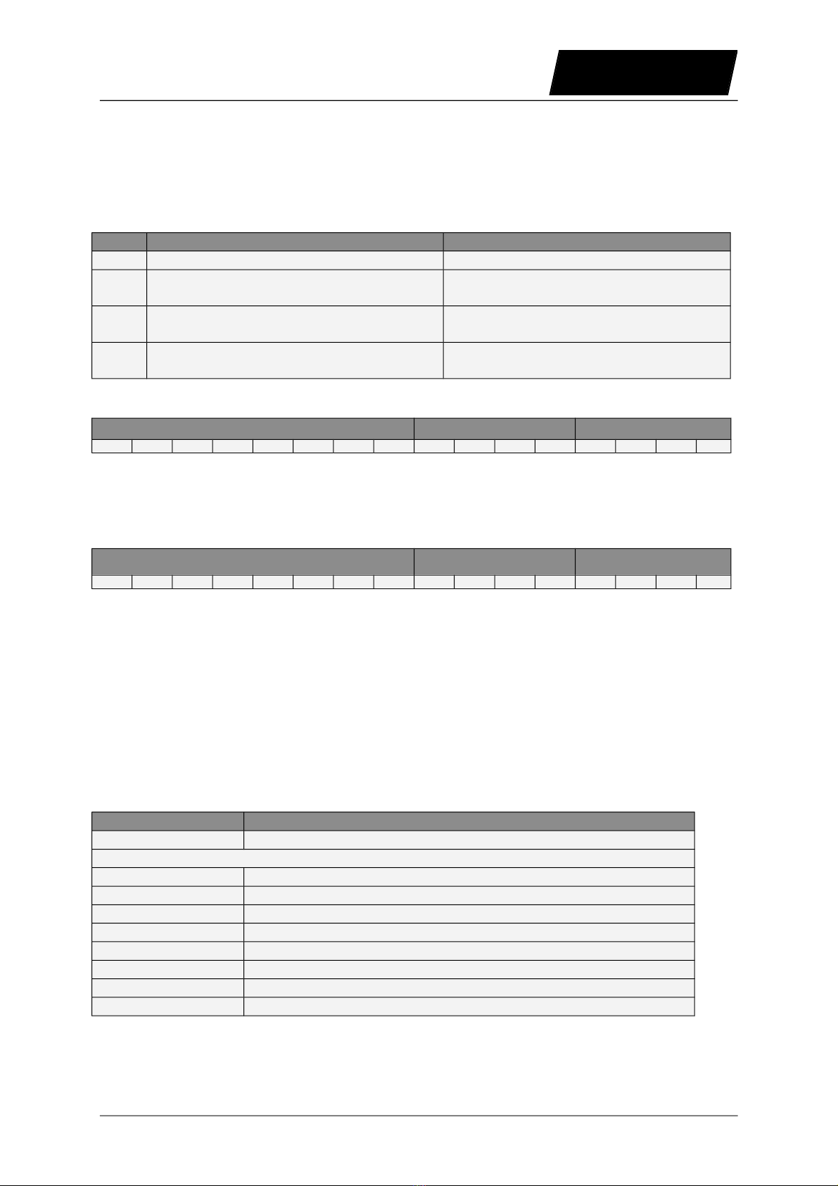
NTI AG LinMot C1150-PN-XC S Series User manual

Documentation of the PROFINET Interface of the following
Drives:
- C11 0-PN-XC
- C12 0-PN-XC
- E12 0-PN-UC
- E14 0-PN-QN
PROFINET Interface
User Manual

LinMot
PROFIBNET Interface
© 2015 NTI AG
This work is protected by copyright.
Under the copyright laws, this publication may not be reproduced or transmitted in any form, electronic or mechanical, including
photocopying,
recording, microfilm, storing in an information retrieval system, not even for didactical use, or translating, in whole or in
part, without the prior written consent of NTI AG.
LinMot® is a registered trademark of NTI AG.
Note
The information in this documentation reflects the stage of development at the time of press and is therefore without obligation.
NTI AG reserves itself the right to make changes at any time and without notice to reflect further technical advance or product
improvement.
Document version 4.4 / W p, September 2015
Page 2/24 User Manual PROFINET Interface / 09/09/2015 NTI AG / LinMot

PROFINET Interface
LinMot
Table of Content
1 SYSTEM OVERVIEW .................................................................................................................... 4
2 INSTALLATION ON SERVO DRIVE .......................................................................................... 4
3 CONNECTING TO THE PROFINET ........................................................................................... 5
3.1.PIN ASSIGNMENT OF THE CONNECTORS X17-X18 ................................................................................... 5
4 PROFINET PARAMETERS ........................................................................................................... 6
5 PROFINET VARIABLES ............................................................................................................... 7
5.1.PROFINET .......................................................................................................................................... 7
5.2.PROFINET: SLOT CONFIGURATION ......................................................................................................... 7
6 PROFINET MODULES .................................................................................................................. 8
7 STATE MACHINE ........................................................................................................................ 16
8 PROFINET DIAGNOSIS .............................................................................................................. 16
ERROR CODES ............................................................................................................................. 16
10 WARN WORD .............................................................................................................................. 16
11 EXAMPLE FOR SIEMENS SIMATIC S7 ................................................................................. 17
11.1.BUS CONFIGURATION (HW CONFIG) .................................................................................................. 17
11.2.HOMING PROCE URE ........................................................................................................................ 18
11.3.EXECUTE MOTION COMMAN : VAI GO TO POS (010XH) ................................................................... 19
11.4.CHANGE A PARAMETER OF THE RIVE WITH THE PARAMETER CHANNEL MO ULE ...................................... 21
12 TROUBLESHOOTING ............................................................................................................... 23
13 CONTACT ADDRESSES ............................................................................................................ 24
NTI AG / LinMot User Manual PROFINET Interface / 09/09/2015 Page 3/24

LinMot
PROFIBNET Interface
1 System overview
T e LinMot PROFINET drives C1150-PN, C1250-PN, E1250-PN and E1450-PN are
PROFINET-IO slaves.
Furt er information on PROFINET can be found under: ttp://www.profibus.com
Programming examples provided by LinMot are listed under:
ttp://www.linmot.com/index.p p?id=141
2 Installation on Servo Drive
For installing t e PROFINET-IO firmware on t e servo drive, start t e LinMot-Talk software
and press t e install firmware button . C oose t e file “Firmware_Buildxxxxxxxx.sct” and
press “Open“. T e wizard will guide you t roug t e installation. W en asking for t e
interface software c oose “PROFINET”:
Press ok and follow t e rest of t e wizard.
Page 4/24 User Manual PROFINET Interface / 09/09/2015 NTI AG / LinMot

PROFINET Interface
LinMot
3 Connecting to the PROFINET
3.1. Pin Assignment of the Connectors X17-X18
T e Et ernet/IP connector is a standard RJ45 female connector wit a pin assignment as
defined by EIA/TIA T568B:
X17 – X18 RealTime Ethernet Connector
Pin Wire color code Assignment 100BASE-TX
1
2
3
4
5
6
7
8
case
WHT/ORG
ORG
WHT/GRN
BLU
WHT/BLU
GRN
WHT/BRN
BRN
-
Rx+
Rx-
Tx+
-
-
Tx-
-
-
-
RJ-45 Use standard patc cables (twisted pair, S/UTP, AWG26) for
wiring. T is type of cable is usually referred to as a “Cat5e-
Cable”.
NTI AG / LinMot User Manual PROFINET Interface / 09/09/2015 Page 5/24

LinMot
PROFIBNET Interface
4 PROFINET Parameters
T e PROFINET Servo drives ave an additional parameter tree branc , w ic can be
configured wit t e distributed LinMot-Talk software. Wit t ese parameters, t e PROFINET
be aviour can be configured. T e software LinMot-Talk can be downloaded from
ttp://www.linmot.com under t e section download, software & manuals.
Dis-/Enable Wit t e Dis-/Enable parameter t e LinMot servo drive can be run
wit out t e PROFINET going online. So in first step t e system can be
configured and run wit out any bus connection.
PROFINET Interface\ Dis-/Enable
Disable Servo drive runs wit out PROFINET.
Enable Servo drive runs only wit a PROFINET connection.
Byte Order Defines t e used byte order.
PROFINET Interface\ Byte/Word Order\Byte Order
Reversed Byte order is reversed. For S7 PLCs select
reversed.
Not reversed Byte order is not reversed.
Word Order Defines t e used word order.
PROFINET Interface\ Byte/Word Order\Word Order
Reversed Word order is reversed. For S7 PLCs select
reversed.
Not reversed Word order is not reversed.
MC CMD Intf Par Order Defines t e used parameter word order.
PROFINET Interface\ Byte/Word Order\MC CMD Intf Par Order
Reversed Order is reversed. CMD Header - Par word 1 - Par
word 0 - Par word 3 - Par word 2 - etc...
Not reversed Order is not reversed. CMD Header - Par word 0 -
Par word 1 - Par word 2 - Par word 3 - etc...
Diagnose Priority Defines t e be aviour of t e diagnostic telegram.
PROFINET Interface\ Diagnose Priority
None Only minimal diagnostic data is transmitted.
Low T e diagnostic data is sent as status information
only.
Hig T e diagnostic data is sent wit ig priority in t e
error state.
Monitoring Channels Defines t e source variable by UPID of t e four monitoring
c annels.
PROFINET Interface\ Monitoring Channels
C annel 1 UPID Source UPID for Monitoring C annel 1
C annel 2 UPID Source UPID for Monitoring C annel 2
C annel 3 UPID Source UPID for Monitoring C annel 3
C annel 4 UPID Source UPID for Monitoring C annel 4
Page 6/24 User Manual PROFINET Interface / 09/09/2015 NTI AG / LinMot

PROFINET Interface
LinMot
PROFINET Variables
5.1. ProfiNet
In t e Variables directory of t e LinMot-Talk t ere is a section \PROFINET containing some
information about t e actual state of t e PROFINET interface:
•Device Type:
Device type string, t is string is fix for eac device type.
•Device Name:
T e Device name can be freely defined by t e user, t is string is
normally defined wit t e HW manager of Step 7 and is used for
identifying t e device in t e PROFINET network.
•MAC ID:
Individual unique MAC address of t e PROFINET-IO device, can be
used to identify a device.
•IP Address:
Actual configured (normally written from t e PLC during power up) IP
address.
•Net Mask:
Net mask for t e IP address.
•Standard Gateway IP Address:
IP address of t e standard gateway.
•Receive Data Counter:
Counts t e received PROFINET-IO data messages up to 1000, t en
restarts wit 0.
•IO Cycle Time:
Actual period time between t e received PROFINET-IO data
messages.
5. . ProfiNet: Slot Configuration
In t is directory t e configured modules for t e Slots 1..7 are displayed. T e configuration of
t e modules is done in t e HW manager of t e Step 7.
NTI AG / LinMot User Manual PROFINET Interface / 09/09/2015 Page 7/24

LinMot
PROFIBNET Interface
6 PROFINET Modules
T e LinMot drive is a PROFINET-IO slave. To configure it wit a PROFINET master, t e
GSD file is used. You can find t e GSD file LINM092D.GSD in t e LinMot-Talk installation
directory (typically C:\Program Files\LinMot\LinTalk-Talk 4 Build
xxxxxxxx\Firmware\PROFINET\GSD).
T ere are t e following modules defined, to be configured according t e demands of t e
desired application:
Control/Status
T is module s ould always be configured. It contains t e Control and Status word, w ic are
described in t e document “User Manual Motion Control Software”.
MC Cmd Interface
T is maps t e MC Command interface of t e drive. Please refer to t e documentation of t e
MC software.
Get Actual Position
Returns t e actual position of t e motor. (32 Bit integer value, resolution 0.1µm)
Get Demand Position
Returns t e demand position of t e motor. (32 Bit integer value, resolution 0.1µm)
Get Current
Returns t e set current of t e motor. (32 Bit integer value, resolution 1mA)
Get StateVar
T e StateVar consists of t e MainState and t e SubState. Please refer to t e table “State
Var” on c apter 3 of t e “User Manual Motion Control Software”.
T e StateVar as all relevant flags and information for clean ands aking wit in one word
and can t erefore replace t e modules “Get MC Header Ec o” and “Get Error Code”.
It’s strongly recommended to use this module for handshaking.
Get WarnWord
Returns t e Warn Word. Please refer to c apter 10.
Get ErrorCode
Returns t e Error Code. Please refer to c apter 9.
Monitoring Channel 1..4
Transmits cyclically t e value of t e variable, w ic is defined by t e Monitoring C annel
Parameter (see c apter 4).
Page 8/24 User Manual PROFINET Interface / 09/09/2015 NTI AG / LinMot

PROFINET Interface
LinMot
Real Time Config
T e Real Time Config module allows access to parameters, variables, curves, error log and
command table. Also restart, start and stop of t e drive is possible. Of course t e Parameter
C annel module works independently from t e MC Cmd Interface. For t is reason c anging
a parameter and sending a motion command can be done in parallel.
Word DO DI
1. Parameter C annel Control Parameter C annel Status
2. Argument (meaning depends on Cmd
ID)
Argument (meaning depends on Cmd
ID)
3. Argument (meaning depends on Cmd
ID)
Argument (meaning depends on Cmd
ID)
4. Argument (meaning depends on Cmd
ID)
Argument (meaning depends on Cmd
ID)
Real Time Config Control
Parameter Command ID to be executed Reserved Command Count
15 14 13 12 11 10 9 8 7 6 5 4 3 2 1 0
T e Parameter C annel Control is split in two parts:
•Parameter Command ID to be executed (bits 8-15), see table Command ID
•Command Count (bits 0-3)
Real Time Config Status
Parameter Status Reserved Command Count
Response
15 14 13 12 11 10 9 8 7 6 5 4 3 2 1 0
T e Parameter C annel Status is split in two parts:
•Parameter Status (bits 8-15), see table Parameter Status
•Command Count Response (bits 0-3)
Command Count
A new command is only evaluated, if t e value of t e command count c anges. In t e
easiest way bit 0 can be toggled.
Parameter Command ID
T is selects t e command.
Possible Commands are:
Command ID Description
00 No Operation
Parameter Access
10 Read ROM Value of Parameter by UPID
11 Read RAM Value of Parameter by UPID
12 Write ROM Value of Parameter by UPID
13 Write RAM Value of Parameter by UPID
14 Write RAM and ROM Value of Parameter by UPID
15 Get minimal Value of Parameter by UPID
16 Get maximal Value of Parameter by UPID
17 Get default Value of Parameter by UPID
NTI AG / LinMot User Manual PROFINET Interface / 09/09/2015 Page 9/24

LinMot
PROFIBNET Interface
Parameter (UPID) List
20 Start Getting UPID List
21 Get next UPID List item
22 Start Getting Modified UPID List
23 Get next Modified UPID List item
Stop / Start / Default
30 Restart drive
31 Set parameter ROM values to default (OS SW)
32 Set parameter ROM values to default (MC SW )
33 Set parameter ROM values to default (Interface SW)
34 Set parameter ROM values to default (Application SW)
35 Stop MC and Application Software (for Flas access)
36 Start MC and Application Software
Curve Service
40 Save all Curves from RAM to Flas
41 Delete all Curves (RAM)
50 Start Adding Curve (RAM)
51 Add Curve Info Block (RAM)
52 Add Curve Data (RAM)
53 Start Modifying Curve (RAM)
54 Modify Curve Info Block (RAM)
55 Modify Curve Data (RAM)
60 Start Getting Curve (RAM)
61 Get Curve Info Block (RAM)
62 Get Curve Data (RAM)
Error Log
70 Get Error Log Entry Counter
71 Get Error Log Entry Error Code
72 Get Error Log Entry Time low
73 Get Error Log Entry Time ig
74 Get Error Code Text Stringlet
Command Table
80 Command Table: Save to Flas
81 Command Table: Delete All Entries (RAM)
82 Command Table: Delete Entry
83 Command Table: Write Entry
84 Command Table: Write Entry Data
85 Command Table: Get Entry
86 Command Table: Get Entry Data
87 Get Presence List of Entries 0..31 from RAM
88 Get Presence List of Entries 32..63 from RAM
89 Get Presence List of Entries 64..95 from RAM
8A Get Presence List of Entries 96..127 from RAM
8B Get Presence List of Entries 128..159 from RAM
8C Get Presence List of Entries 160..191 from RAM
8D Get Presence List of Entries 192..223 from RAM
8E Get Presence List of Entries 224..255 from RAM
Page 10/24 User Manual PROFINET Interface / 09/09/2015 NTI AG / LinMot

PROFINET Interface
LinMot
Parameter Status Description
00 OK, done
02 Command Running / Busy
04 Block not finis ed (Curve Service)
05 Busy
C0 UPID Error
C1 Parameter Type Error
C2 Range Error
C3 Address Usage Error
C5 Error: Command 21 “Get next UPID List item” was executed
wit out prior execution of “Start Getting UPID Lis”
C6 End of UPID List reac ed (no next UPID List item found)
D0 Odd Address
D1 Size Error (Curve Service)
D4 Curve already defined / Curve not present (Curve Service)
NTI AG / LinMot User Manual PROFINET Interface / 09/09/2015 Page 11/24

LinMot
PROFIBNET Interface
Overview Parameter access:
Word DO DI
1. Parameter C annel Control Parameter C annel Status
2. Parameter UPID Parameter UPID
3. Parameter Value Low Parameter Value Low
4. Parameter Value Hig Parameter Value Hig
Overview Curve access:
Word DO DI
1. Parameter C annel Control Parameter C annel Status
2. Curve Number Curve Number
3. Data Value Low / Info Block size Data Value Low / Info Block size
4. Data Value Hig / Data Block size Data Value Hig / Data Block size
Start getting UPID List:
Word DO DI
1. Parameter C annel Control Parameter C annel Status
2. Start UPID (searc from t is UPID) -
3. - -
4. - -
Get next UPID List item:
Word DO DI
1. Parameter C annel Control Parameter C annel Status
2. - UPID found
3. - Address Usage
4. - -
Address Usage:
Not used for Hash calculation
Life Parameter
ROM Write
ROM Read
RAM Write
RAM Read
15 14 13 12 11 10 9 8 7 6 5 4 3 2 1 0
Start getting Modified UPID List (Command ID 22h):
Word DO DI
1. Parameter C annel Control Parameter C annel Status
2. Start UPID (searc from t is UPID) -
3. - -
4. - -
Page 12/24 User Manual PROFINET Interface / 09/09/2015 NTI AG / LinMot

PROFINET Interface
LinMot
Get next Modified UPID List item (Command ID 23h):
Word DO DI
1. Parameter C annel Control Parameter C annel Status
2. - UPID found
3. - Data Value Low
4. - Data Value Hig
Get Error Log Entry Counter (Command ID 70h):
Word DO DI
1. Parameter C annel Control Parameter C annel Status
2. - -
3. - Number of Logged Errors
4. - Number of Occurred Errors
Get Error Log Entry Error Code (Command ID 71h):
Word DO DI
1. Parameter C annel Control Parameter C annel Status
2. Entry Number (0..20) Entry Number
3. - Logged Error Code
4. - -
Get Error Log Entry Time Low (Command ID 72h):
Word DO DI
1. Parameter C annel Control Parameter C annel Status
2. Entry Number (0..20) Entry Number
3. - Entry Time Low Word
4. - Entry Time Mid Low Word
Get Error Log Entry Time High (Command ID 73h):
Word DO DI
1. Parameter C annel Control Parameter C annel Status
2. Entry Number (0..20) Entry Number
3. - Entry Time Mid Hig Word
4. - Entry Time Hig Word
T e Error Log Entry Time consists of 32Bit ours (Time Hig ) and 32Bit ms (Time Low).
Get Error Code Text Stringlet (Command ID 74h):
Word DO DI
1. Parameter C annel Control Parameter C annel Status
2. Error Code Error code
3. Stringlet Number (0..7) Stringlet Byte 0 and 1
4. - Stringlet Byte 2 and 3
NTI AG / LinMot User Manual PROFINET Interface / 09/09/2015 Page 13/24

LinMot
PROFIBNET Interface
Command Table: Save to Flash (Command ID 7 h):
Word DO DI
1. Parameter C annel Control Parameter C annel Status
2. - -
3. - -
4. - -
For t is command, t e MC software must be stopped (wit command “35 : Stop MC and
Application Software”).
T e PROFINET Interface will stay active w ile t e MC software is stopped.
Command Table: Delete All Entries (RAM) (Command ID 81h)
Word DO DI
1. Parameter C annel Control Parameter C annel Status
2. - -
3. - -
4. - -
Command Table: Delete Entry (Command ID 82h):
Word DO DI
1. Parameter C annel Control Parameter C annel Status
2. Entry Number Entry Number
3. - -
4. - -
Command Table: Write Entry (Command ID 83h)
Word DO DI
1. Parameter C annel Control Parameter C annel Status
2. Entry Number Entry Number
3. Block Size (even number of bytes) Block Size
4. - -
Command Table: Write Entry Data (Command ID 84h)
Word DO DI
1. Parameter C annel Control Parameter C annel Status
2. Entry Number Entry Number
3. Data Data
4. Data Data
Command Table: Get Entry (Command ID 8 h)
Word DO DI
1. Parameter C annel Control Parameter C annel Status
2. Entry Number Entry Number
3. - Block Size
4. - -
Page 14/24 User Manual PROFINET Interface / 09/09/2015 NTI AG / LinMot

PROFINET Interface
LinMot
Command Table: Get Entry Data (Command ID 86h)
Word DO DI
1. Parameter C annel Control Parameter C annel Status
2. Entry Number Entry Number
3. - Data
4. - Data
Command Table: Get Entry List (0..7) (Command IDs 87h .. 8Eh)
Word DO DI
1. Parameter C annel Control Parameter C annel Status
2. - Offset in bytes
3. - Bit field (Bit set= undefined / Bit cleared =
used)
4. - Bit field (Bit set= undefined / Bit cleared =
used)
Furt er documentation on ow to configure a drive by fieldbus and andle curves
can be found on t e additional manual “Parameterization of LinMot SG5 servo
drives over Fieldbus Interfaces”.
NTI AG / LinMot User Manual PROFINET Interface / 09/09/2015 Page 15/24

LinMot
PROFIBNET Interface
7 State Machine
Please refer to “User Manual Motion Control Software”.
8 PROFINET Diagnosis
T e LinMot drive supports 12 bytes of diagnostic data. T e diagnosis telegram is according
t e following table:
Byte Description
0..5 Data according PROFINET-IO standard
6..7 Extended Diagnosis Header and stuffing
8..9 Warn Word (see c apter 10 for description)
10..11 Error Code (see c apter 9 for description)
9 Error Codes
Please refer to “User Manual Motion Control Software” for t e Error Codes of t e MC
Software. T e PROFINET Interface as t e following additional Error Codes:
Error Code
Hexadecimal
Error Description
C1 Fatal Error: drive not supported
C2 Config Error: Invalid MACID
C3 IO Err: Connection lost
10 Warn Word
Please refer to “User Manual Motion Control Software”.
Page 16/24 User Manual PROFINET Interface / 09/09/2015 NTI AG / LinMot

PROFINET Interface
LinMot
11 Example for Siemens Simatic S7
T e following example s ows t e oming procedure, t e execution of a motion command
and t e c ange of a parameter toget er wit S7 and Simatic from Siemens:
11.1. Bus configuration (HW Config)
NTI AG / LinMot User Manual PROFINET Interface / 09/09/2015 Page 17/24

LinMot
PROFIBNET Interface
11. . Homing procedure
1. Release lock state: Control Word = 0000 (Only needed if StateVar MainState is 00 ) :
StateVar MainState becomes 02 : Ready to Switc On
2. Homing: Control Word = 083F
StateVar MainState becomes 09 : Homing, Homing is finis ed if SubState becomes 0F
3. Enter Operational State: Control Word = 003F
StateVar MainState becomes 08 : Operation Enabled, Drive is ready for motion commands
Page 18/24 User Manual PROFINET Interface / 09/09/2015 NTI AG / LinMot

PROFINET Interface
LinMot
11.3. Execute Motion Command: VAI Go To Pos (010xh)
Name Description Scaled Value Int. Value (HEX)
Header VAI Go To Pos (010x ) 257 0101
1. Par Target Position: 50mm 0007A120
2. Par Maximal Velocity: 1m/s 000F4240
3. Par Acceleration: 10m/s^2 000F4240
4. Par Deceleration: 10m/s^2 000F4240
In t e case of \Parameters\PROFINET Interface\Byte/Word Order\MC CMD Intf Par
Order\not reversed (default setting):
In t e case of \Parameters\PROFINET Interface\Byte/Word Order\MC CMD Intf Par
Order\ reversed:
To send t e next command t e count nibble as to be c anged. T e eader for t e next VAI
Go To Pos command is t erefore 0100.
NTI AG / LinMot User Manual PROFINET Interface / 09/09/2015 Page 19/24

LinMot
PROFIBNET Interface
As it appears wit LinMot-Talk after “Read Command” in t e Control Panel:
Page 20/24 User Manual PROFINET Interface / 09/09/2015 NTI AG / LinMot
This manual suits for next models
3
Table of contents
Other NTI AG Servo Drive manuals
Popular Servo Drive manuals by other brands

Santerno
Santerno Sinus M user manual

Kinco
Kinco CD3 user manual

Mitsubishi Electric
Mitsubishi Electric MR-J4-10B(-RJ) instruction manual

Motor Power Company
Motor Power Company DMR 50-5/50 V3.0 installation guide

Mitsubishi Electric
Mitsubishi Electric MELSERVO-J4 series instruction manual

Bosch
Bosch Rexroth IndraDrive Mi Project planning manual

Omron
Omron sysmac 1S Series Startup guide

Axor
Axor CD180 Service manual

Delta
Delta ASDA-A3 Series user manual

Oriental motor
Oriental motor BX Series operating manual

LS ELECTRIC
LS ELECTRIC iX7NH Series quick start guide

Rockwell Automation
Rockwell Automation Allen-Bradley Kinetix 300 2097-V31PR0 user manual