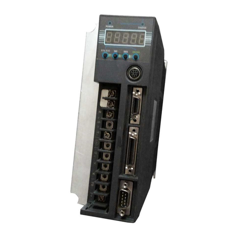
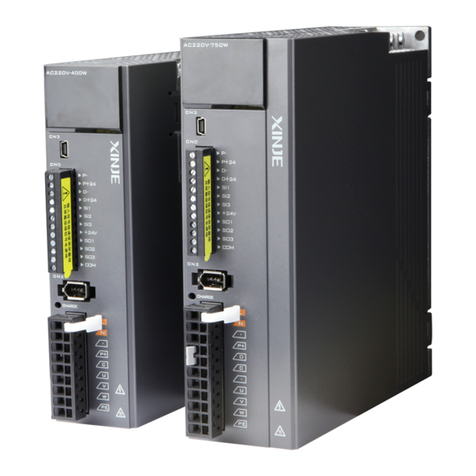
Xinje DS5K Series User manual

DS5K series servo driver
User manual
WUXI XINJE ELECTRIC CO., LTD.
Data No. SC5 03 20200217 1.1


Basic explanation
Thank you for purchasing Xinje DS5F series servo driver products.
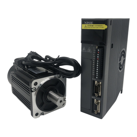
This manual mainly introduces the product information of DS5K series servo driver and MS
series servo motor.
Before using the product, please read this manual carefully and connect the wires on the premise
of fully understanding the contents of the manual.
Please deliver this manual to the end user.
This manual is suitable for the following users
Designer of servo system
Installation and wiring workers
Commissioning and servo debugging workers
Maintenance and inspection workers
Get the manual
Please consult the supplier, agent and office who purchased the product.
Declaration of liability
Although the contents of the manual have been carefully checked, errors are inevitable, and we
cannot guarantee complete consistency.
We will often check the contents of the manual and make corrections in the subsequent versions.
We welcome your valuable comments.
If there is any change to the contents introduced in the manual, please understand without
further notice.
Contact information
Tel: 400-885-0136
Fax: 0510-85111290
Address: Floor 4, building 7, creative industry park, No. 100, DiCui Road, Wuxi City
Postcode: 214072
WUXI XINJE ELECTRIC CO., LTD. Copyright
Without explicit written permission, this material and its contents shall not be copied, transmitted
or used, and the violator shall be liable for the losses caused. All rights provided in the patent
license and registration including utility module or design are reserved. Jan. 2019

The problems that may arise during the use of the product are basically listed in the safety precautions,
and all are indicated by the two levels of attention and danger. For other unmentioned matters, please
follow the basic electrical operation rules.
Caution
When used incorrectly, there may be danger, moderate injury or minor injury, and
property loss.
Danger
When used incorrectly, it may cause danger, personal casualties or serious injuries,
as well as serious property losses.
Attention to Product Confirmation
1.Do not install damaged drives, drives that lack spare parts, or drives whose models do not meet the
requirements.
Installation Notes
1. Before installing wiring, be sure to disconnect the power supply to prevent electric shock.
2. It is forbidden to expose the product to water, corrosive gases, flammable gases and other
substances, causing electric shock and fire hazards.
3. Do not touch the conductive part of the product directly, which may cause misoperation and
malfunction.
Cautions for wiring
1. Please connect AC power to LN or L1/L2/L3 or R/S/T on the dedicated power terminal of the
driver. Do not connect the output terminals U, V, W of the driver to the three-phase power supply.
2. Please connect the ground wire correctly. Poor grounding may cause electric shock. Please use
2mm2wire to ground the ground terminal of the driver.
3. Please lock the fixed screw of the terminal, otherwise it may cause fire.
4. Be sure to disconnect all external power supply before wiring the driver.
5. Wiring, please ensure that the encode line, power line is loose, do not tighten, lest cable damage.
Before using this product, please read this part carefully and operate after fully understanding
the use, safety and precautions of the product. Please connect the product correctly on the
premise of paying great attention to safety.
Be sure to review this section carefully before use this product. In precondition of security, wire
the product correctly.
Safety Precautions
PrePrecaPrecautio
ns

Operation Cautions
1. Do not touch the rotating part of the motor after the driver is running. There is a danger of injury.
2. Please pay attention to the test run of the motor once, do not connect the motor with the machine,
there is the possibility of injury.
3. After connecting the machine, please set the appropriate parameters before running, otherwise it
may cause the machine out of control or failure.
4. In operation, do not touch the radiator, there is a risk of scald.
5. Under power-on condition, do not change the wiring, there is a risk of injury.
6. Do not switch power frequently. If you need to switch power many times, please control it once in 2
minutes.
Maintenance and inspection
1. Do not touch the inside of servo driver and servo motor, otherwise it may cause electric shock.
2. When the power is started, it is forbidden to remove the driver panel, otherwise it may cause electric
shock.
3. Within 10 minutes of power off, the terminal should not be contacted. Otherwise, the residual
voltage may cause electric shock.
Wiring attention
1. Do not cross the power line and the control signal line from the same pipeline, nor tie them together.
The power line and the control signal line are separated by more than 30 centimeters.
2. For signal line and encoder (PG) feedback line, please use multi-stranded wire and multi-core
stranded integral shielding line. For wiring length, the longest signal input line is 3 meters and the
longest PG feedback line is 20 meters.


- 1 -
Catalog
►► CONFIRMATION ON PRODUCT ARRIVAL..................................................................................4
1 SELECTION OF SERVO SYSTEM .........................................................................................................5
1.1 SELECTION OF SERVO DRIVER ..................................................................................................................5
1.1.1 Model name ......................................................................................................................................5
1.1.2 Description of each part...................................................................................................................5
1.1.3 Performance specification................................................................................................................5
1.2SERVO MOTOR SELECTION .......................................................................................................................6
1.2.1 Model name ......................................................................................................................................6
1.2.2 Description of each part...................................................................................................................7
1.3 CABLE SELECTION....................................................................................................................................7
1.3.1 Model name ......................................................................................................................................7
1.3.2 Description of each part...................................................................................................................8
1.4 SELECTION OF OTHER ACCESSORIES.......................................................................................................10
1.4.1 Selection of regenerative resistance ...............................................................................................10
2 INSTALLATION OF SERVO SYSTEM................................................................................................12
2.1 SERVO DRIVER INSTALLATION ...............................................................................................................12
2.1.1 Installation site...............................................................................................................................12
2.1.2 Environment condition ...................................................................................................................12
2.1.3 Installation standard.......................................................................................................................12
2.2 SERVO MOTOR INSTALLATION................................................................................................................13
2.2.1 Environment condition ...................................................................................................................13
2.2.2 Installation cautions .......................................................................................................................14
2.2.3 Installation environment.................................................................................................................15
2.3 SERVO CABLE INSTALLATION.................................................................................................................16
2.3.1 Cable selection ...............................................................................................................................16
2.3.2 Xinje cable specification.................................................................................................................17
2.4 SERVO DRIVER DIMENSION.....................................................................................................................19
2.5SERVO MOTOR DIMENSION.....................................................................................................................20
3 SERVO SYSTEM WIRING .....................................................................................................................24
3.1 MAIN CIRCUIT WIRING ...........................................................................................................................25
3.1.1 Servo driver terminal arrangement ................................................................................................25
3.1.2 Main circuit terminal......................................................................................................................25
3.1.3 CN0, CN2 terminal.........................................................................................................................26
3.1.4 Communication port.......................................................................................................................27
3.2 CLASSIFICATION AND FUNCTION OF SIGNAL TERMINALS........................................................................28
3.2.1 Pulse signal ....................................................................................................................................28
3.2.2 SI input signal.................................................................................................................................29
3.2.3 SO output signal.............................................................................................................................29
3.2.4 Encoder feedback output signal......................................................................................................30
4 OPERATE PANEL ...................................................................................................................................31
4.1 BASIC OPERATION..................................................................................................................................31
4.1.1 Operating panel description...........................................................................................................31
4.1.2 Button operation.............................................................................................................................31
4.2 OPERATION DISPLAY..............................................................................................................................32
4.3 GROUP UMONITOR PARAMETER............................................................................................................33
4.4 GROUP FAUXILIARY FUNCTION PARAMETERS .......................................................................................36
4.4.1 Group F0........................................................................................................................................36
4.4.2 Group F1........................................................................................................................................37
4.5 FAULT ALARM HANDLING ......................................................................................................................38
4.6 PARAMETER SETTING EXAMPLE .............................................................................................................39
4.7 CHANGE MOTOR CODE ...........................................................................................................................39
5 OPERATION OF SERVO SYSTEM ......................................................................................................40
5.1 CONTROL MODE SELECTION AND SWITCHING.........................................................................................40
5.1.1 Control mode selection...................................................................................................................40

- 2 -
5.1.2 Control mode switching..................................................................................................................41
5.2 BASIC FUNCTION SETTING......................................................................................................................42
5.2.1 Jog operation..................................................................................................................................42
5.2.2 Servo enable setting........................................................................................................................43
5.2.3 Rotation direction switching...........................................................................................................44
5.2.4 Stop mode .......................................................................................................................................44
5.2.5 Power-off brake..............................................................................................................................46
5.2.6 Braking setting................................................................................................................................49
5.3POSITION CONTROL................................................................................................................................50
5.3.1 General position control.................................................................................................................50
5.3.2 Position control (external pulse command)....................................................................................59
5.3.3 Position control (Internal command) .............................................................................................62
5.4 SPEED CONTROL.....................................................................................................................................70
5.4.1 Speed mode general control ...........................................................................................................70
5.4.2 Speed control (internal speed)........................................................................................................72
5.5 TORQUE CONTROL..................................................................................................................................76
5.5.1 Torque general mode......................................................................................................................76
5.5.2 Torque control (internal setting) ....................................................................................................76
5.6 ABSOLUTE VALUE SYSTEM.....................................................................................................................77
5.6.1 Absolute system setting...................................................................................................................77
5.6.2 Replace the battery.........................................................................................................................77
5.6.3 The upper limit of turns ..................................................................................................................78
5.6.4 Read absolute position through communication.............................................................................79
5.6.5 Reset absolute position...................................................................................................................80
5.7 AUXILIARY FUNCTIONS..........................................................................................................................81
5.7.1 Anti-blocking protection.................................................................................................................81
5.7.2 Torque limit....................................................................................................................................82
5.7.3 Speed limit ......................................................................................................................................83
5.7.4 I/O signal distribution ....................................................................................................................83
5.7.5 Output terminal function ................................................................................................................84
5.7.6 Input terminal function...................................................................................................................89
5.7.7 Time limit curve of overload protection ......................................................................................... 90
5.8 ENCODER ABZ PHASE FREQUENCY DIVISION OUTPUT............................................................................92
6 SERVO GAIN ADJUSTMENT................................................................................................................94
6.1 OVERVIEW OF SERVO GAIN ADJUSTMENT...............................................................................................94
6.1.1 Overview and process.....................................................................................................................94
6.1.2 The difference of these adjustment modes ......................................................................................95
6.1.3 Model loop control .........................................................................................................................95
6.1.4 Torque disturbance observation.....................................................................................................97
6.2 ROTARY INERTIA PRESUMPTION.............................................................................................................97
6.2.1 Overview.........................................................................................................................................97
6.2.2 Notes...............................................................................................................................................97
6.2.3 Operation tool ................................................................................................................................98
6.2.4 Operation steps...............................................................................................................................98
6.3 FAST ADJUSTMENT............................................................................................................................... 102
6.3.1 Overview.......................................................................................................................................102
6.3.2 Fast adjustment steps....................................................................................................................102
6.3.3 Rigidity level corresponding gain parameters..............................................................................102
6.3.4 Notes.............................................................................................................................................105
6.4 AUTO-TUNING......................................................................................................................................105
6.4.1 Overview.......................................................................................................................................105
6.4.2 Notes.............................................................................................................................................106
6.4.3 Operation tools.............................................................................................................................106
6.4.4 Internal instruction auto-tuning steps...........................................................................................106
6.4.5 External instruction auto-tuning steps..........................................................................................111
6.4.6 Related parameters.......................................................................................................................115
6.5 MANUAL ADJUSTMENT ........................................................................................................................116
6.5.1 Overview.......................................................................................................................................116
6.5.2 Adjustment steps........................................................................................................................... 117
6.5.3 Gain parameters for adjustment...................................................................................................118
6.6 ADAPTIVE ............................................................................................................................................119
6.6.1 Overview.......................................................................................................................................119

- 3 -
6.6.2 Notes.............................................................................................................................................119
6.6.3 Operation steps.............................................................................................................................119
6.6.4 Inertia mode and related parameters ...........................................................................................120
6.6.5 Recommended inertia ratio parameters .......................................................................................120
6.6.6 Adaptive parameters effect ...........................................................................................................121
6.6.7 Invalid parameters when adaptive effective .................................................................................122
6.7 VIBRATION SUPPRESSION .....................................................................................................................122
6.7.1 Overview.......................................................................................................................................122
6.7.2 Operation tools.............................................................................................................................122
6.7.3 Vibration Suppression (Panel) .....................................................................................................122
6.7.3 Vibration suppression (panel) ......................................................................................................123
6.7.4 Vibration suppression (PC software) ...........................................................................................124
6.7.5 Vibration suppression (manual setting)........................................................................................124
6.7.6 Vibration suppression (quick FFT) ..............................................................................................125
6.7.7 Notch filter....................................................................................................................................126
6.8 GAIN ADJUSTMENT...............................................................................................................................128
6.8.1 Load shaking ................................................................................................................................128
6.8.2 Vibration.......................................................................................................................................128
6.8.3 Noise.............................................................................................................................................128
7 ALARM....................................................................................................................................................129
7.1 ALARM CODE LIST................................................................................................................................129
7.2 ANALYSIS OF ALARM TYPES.................................................................................................................131
8 MODBUS-RTU COMMUNICATION ..................................................................................................141
8.1 COMMUNICATION WIRING....................................................................................................................141
8.2 COMMUNICATION PARAMETERS...........................................................................................................143
8.3 COMMUNICATION PROTOCOL...............................................................................................................145
8.3.1 Character structure ......................................................................................................................145
8.3.2 Communication data structure .....................................................................................................145
8.4 COMMUNICATION EXAMPLE.................................................................................................................147
8.4.1 Communication with Xinje PLC ...................................................................................................147
9 APPENDIX...............................................................................................................................................148
APPENDIX 1. GROUP PPARAMETERS .........................................................................................................148
APPENDIX 2. UX-XX MONITORING PARAMETERS......................................................................................164
APPENDIX 3. FX-XX AUXILIARY FUNCTION PARAMETERS ........................................................................167
APPENDIX 4. MODBUS ADDRESS LIST.........................................................................................................167
APPENDIX 5. Q&A.....................................................................................................................................172
APPENDIX 6. GENERAL DEBUGGING STEPS.................................................................................................174
APPENDIX 7. APPLICATION EXAMPLE ........................................................................................................175
APPENDIX 8. SERVO GENERAL MODE PARAMETERS ...................................................................................177
Appendix 8.1 Basic parameters.............................................................................................................177
Appendix 8.2 External pulse position mode general parameters ..........................................................177
Appendix 8.3 Internal position mode general parameters.....................................................................178
Appendix 8.4 Internal torque control general parameters ....................................................................178
Appendix 8.5 Internal speed control general parameters .....................................................................178
Appendix 8.6 External pulse speed control general parameters ...........................................................179
APPENDIX 9. TORQUE-SPEED CHARACTERISTIC CURVE..............................................................................180
APPENDIX 10. LIST OF MODEL SELECTION AND CONFIGURATION...............................................................183

►► Confirmation on product arrival
After the product arrives, please confirm the integrity of the product in the following aspects.
Items
Notes
Does the product on arrival match the
specified model?
Please confirm according to the nameplate of servo motor
and servo unit.
Does the servomotor shaft rotate
smoothly?
The servo motor shaft is normal if it can be turned
smoothly by hand. Servo motors with brakes, however,
cannot be turned manually.
Is there any damage?
Check the overall appearance, and check for damage or
scratches that may have occurred during shipping.
Are there any loose screws?
Check screws for looseness using a screwdrive.
Is the motor code the same with the
code in drive?
Check the motor code marked on the nameplates of the
servomotor and the parameter U3-00 on the servo drive.
If any of the above is faulty or incorrect, contact Xinje or an authorized distributor.

1 Selection of servo system
1.1 Selection of servo driver
1.1.1 Model name
DS 5-2 P- PTA
Display Encoder type
TCommunication
encoder
Display Rated output
power
0P1 100W
0P2 200W
0P4 400W
0P7 750W
1P5 1.5KW
2P3 2.3KW
2P6 2.6KW
Display Product name
DS Servo driver
Display Product series
5K Standard
Display Rated input voltage
2AC220V
4AC380V
3P0 3KW
1.1.2 Description of each part
1.1.3 Performance specification
Servo unit
DS5K series servo drive
Applicable encoder
Standard: 17-bit/23-bit communication encoder
Input power supply
DS5□-2□P□-PTA: Single/three phases AC200-240V, 50/60Hz
[single phase AC200-240V 50/60Hz is used for less than 1.5KW
(excluding 1.5KW);
Three phase AC200-240V 50/60Hz is recommended for 1.5KW and
above.
(if single-phase power supply, please connect it to R and T, otherwise, the
parameter memory will be affected in case of power failure)
DS5□-4□P□-PTA: three-phase AC340~420V, 50/60Hz
Control mode
Three-phase full-wave rectifier IPM PWM control sinusoidal current
drive mode
Using
condition
Using
temperature
-10~+40 ℃

Storage
temperature
-20~+60 ℃
Environment
humidity
Below 90%RH (no condensation)
Vibration
resistance
4.9m/s2
Structure
Pedestal installation
1.2 Servo motor selection
1.2.1 Model name
MS5S –80 ST E –C S 02430 B Z - 2 0P7 –S01
Name Rated power (KW)
0P2 0.2
0P4 0.4
0P7 0.75
Name Voltage level
2 220V
4 380V
Name Power-off brake
Empty without
Z with
Name Shaft
A No key
B With key
Name Inertia
MS5S Low inertia
MS5G Middle inertia
MS5H High inertia
Name Seat number
60 60 seat
80 80 seat
Name Product name
ST Sine drive motor
Name Encoder type
CMagnetic encoder
TPhotoelectric
encoder
Name Rated torque (N·m)
00630 0.637
01330 1.3
Rated speed (rpm)
3000
3000
Name Encoder accuracy
SSingle circle 17-bit
MMulti-circle 17-bit
USingle circle 23-bit
LMulti-circle 23-bit
Name Design number
S01 standard
02430 2.39 3000
Name Product name
empty No oil seal
E With oil seal
S02 Small Aviation Plug
Type
Note: At present, only the combination of CS, CM, TL and T is selected for the type of encoder.

1.2.2 Description of each part
1.3 Cable selection
1.3.1 Model name
Encoder cable
CP-SP- -02
Display Length (M)
03 3
Display Plug type
SP 9-core amp plug
Display Cable type
CP Normal
Display Plug type
M No battery box
CPT High flexibility
SW 7-core aviation plug
SL 15-core aviation plug
SC 10-core small aviation plug
05 5
08 8
12 12
16 16
20 20
B With battery box
BM With battery box
ZDL Full-sized aviation plug
Power cable
Display Length (M)
Display Plug type
P4-core amp plug
W6-core waterproof small
aviation plug
Display Cable type
CM Normal
CMT High flexibility
Display Cable type
L 4-core small aviation plug
XL 4-core medium aviation plug
CM-L 15-M-03
Display Diameter(mm²)
07 0.75
15 1.5
25 2.5
60 6
03 3
05 5
08 8
MMagnetic
encoder
Empty Optical encoder
D O terminal
Encoder
frame
flange
Output Shaft (Drive Shaft)

Brake cable explanation
For 80 and below flange motors with suffix S01, the brake cable model shall be selected:
CB-P03-length (common material) / CBT-P03-length (high flexible material).
Suitable for 750W and below motor with suffix S02: CMBT-W07-M-length.
For the MS5G 130 flange medium inertia brake motor, the cable shall be selected integrated
power cable and brake cable type.
The standard wiring length of Xinje is 2m, 3m, 5m, 8m, 10m, 12m, 16m and 20m.
1.3.2 Description of each part
Encoder cable
(1) Pin definition of encoder on servo driver side
Connector appearance
Pin definition
No.
Definition
1
26
5
4
3
1
5V
2
GND
3
/
4
/
5
485+
6
485-
(2) Cable connection of encoder on motor side
Connector pins
Pin definition
Suitable model
No.
Definition
1
2
3
4
5
6
7
8
9
1
Battery +
40, 60, 80 flange
-S01 motor
2
Battery -
3
Shielded cable
4
485+
5
485-
6
/
7
5V
8
GND
9
/
1
34
5
6
72
No.
Definition
40, 60, 80 flange
-S02 motor
1
Shielded cable
2
Battery +
3
Battery -
4
485+
5
485-
7
5V
8
GND
2
345
6 7 8 9 10
11 12 13
14 15
1
No.
Definition
110 and above flange
motor
1
Shielded cable
2
/
3
485-
4
485+
5
/
6
GND
7
Battery -
8
5V
9
Battery +

Connector pins
Interface definition
Suitable model
No.
definition
67
8
1
23
4
5
9
10
1
/
130 flange medium inertia
motor
2
5V
3
GND
4
485+
5
485-
6
Battery +
7
Battery -
8
/
9
/
10
Shielded cable
Battery box description:
1) The encoder including the cable definition of battery +, battery- is for the absolute motor, and
the non-absolute motor cable has no such pin.
2) Only the cable of absolute value motor has external battery box, which contains a 3.6V/2.7Ah
large capacity battery, and has the function of replacing batteries when power cut. The using life is
more than two years. Please refer to chapter 5.7.2 change battery.
Power cable
(1) Pin definition of power cable on servo driver side
Connector
appearance
Pin definition
Color
Definition
Brown
U
Black
V
Blue
W
Yellow-green
PE
(2) Power cable connection on motor side
Connector pins
Pin definition
Suitable model
No.
Definition
1
2
3
4
1
U
40, 60, 80 flange
-S01 motor
2
W
3
V
4
PE
21
No.
Definition
40, 60, 80 flange
-S01 motor brake
1
BK
2
BK
12
3
4
5
6
No.
Definition
750W and below S02 small aviation
plug motor
1
PE
2
U
3
V
4
W
5
BK
6
BK
1
2
3
4
No.
Definition
110 and above motor (include 130 flange

1
PE
medium inertia motor without brake)
2
U
3
V
4
W
Connector pins
Interface definition
Suitable model
No.
Definition
1
345
67
2
1
PE
130 flange medium motor with brake
2
U
3
V
4
W
5
BK+
6
BK-
7
/
Brake pins:
The cable including BK pin is used for the brake motor. The cable of the non-brake motor has no BK
pin.
1.4 Selection of other accessories
1.4.1 Selection of regenerative resistance
When the servo motor is driven by the generator mode, the power returns to the servo amplifier side,
which is called regenerative power. The regenerated power is absorbed by charging the smooth
capacitor of the servo amplifier. After exceeding the rechargeable energy, the regenerative resistance is
used to consume the regenerative power.
The servo motor driven by regenerative (generator) mode is as follows:
The deceleration stop period during acceleration and deceleration operation;
Running vertically and axially;
When the external load drives the motor to rotate.
Servo driver model
Regenerative resistance connection terminals
DS5□-P□-PTA
(1) Using built-in regenerative resistance, short P + and D terminals, P + and
C are disconnected.
(2) Use external regenerative resistance, connect regenerative resistance to P
+ and C terminals, remove P + and D short wiring, P0-25 = power value,
P0-26 = resistance value.
Note: if software version U2-07 < 3700, the parameter P0-24 should be set.
The value of 0 is for the built-in resistance to take effect, and the value of 1 is
for the external resistance to take effect.
It no needs to set P0-24 for the firmware version U2-07≥3700, just keep
default value.

The following table is the recommended specifications of external regenerative resistance for each type
of motor.
Servo driver model
Rmin
(Not less than this value)
External regenerative
resistance
(Recommended
resistance value)
External regenerative
resistance
(Recommended power
values)
DS5K-20P1-PTA
50Ω
50Ω-100Ω
Above 200W
DS5K-20P2-PTA
DS5K-20P4-PTA
40Ω
40Ω-100Ω
Above 500W
DS5K-20P7-PTA
DS5K-21P5-PTA
25Ω
25Ω-50Ω
Above 1000W
DS5K-22P3-PTA
DS5K-22P6-PTA
DS5K-43P0-PTA
55Ω
55Ω - 75Ω
Above 1000W
Note:
(1) The smaller the resistance is, the faster the discharge will be, but the smaller the resistance is, the
easier the breakdown resistance will be. Therefore, please close to the the lower limit but not be less
than the lower limit when choosing the type.
(2) When wiring, please use high-temperature flame-retardant wire, and the regenerative resistance
surface can not contact with the wire.

2 Installation of servo system
2.1 Servo driver installation
2.1.1 Installation site
Please install it in the installation cabinet without sunshine or rain.
Do not use this product near corrosive and flammable gas environments such as hydrogen sulfide,
chlorine, ammonia, sulfur, chlorinated gas, acid, alkali, salt, etc.
Do not install in high temperature, humidity, dust, metal dust environment;
No vibration place.
2.1.2 Environment condition
Item
Description
Use ambient temperature
-10~40℃
Use ambient humidity
-20~90%RH (no condensation)
Storage temperature
-20~60℃
Storage humidity
-20~90%RH (no condensation)
2.1.3 Installation standard
Be sure to comply with the installation standard in the control cabinet shown in the figure below. This
standard is applicable to the situation where multiple servo drivers are installed side by side in the
control cabinet (hereinafter referred to as "when installed side by side").
Servo Drive Orientation
Install the servo drive perpendicular to the wall so the front panel containing connectors faces outward.
Cooling
As shown in the figure above, allow sufficient space around each servo drive for cooling by cooling
fans or natural convection.
Side-by-side Installation
When install servo drives side by side as shown in the figure above, make at least 10mm between and
at least 50mm above and below each servo drive. Install cooling fans above the servo drives to avoid
excessive temperature rise and to maintain even temperature inside the control panel.
Environmental Conditions in the Control Panel
Servo driver working ambient Temperature: -10~40 ℃
Humidity: 90%RH or less

Vibration: 4.9m/s2
Condensation and Freezing: None
Ambient Temperature for Long-term Reliability: 50°C maximum
2.2 Servo motor installation
MS series servomotors can be installed either horizontally or vertically. The service life of the
servomotor can be shortened or unexpected problems might occur if it is installed incorrectly or in an
inappropriate location. Follow these installation instructions carefully.
CAUTION
1.The end of the motor shaft is coated with antirust. Before installing, carefully remove all of the
paint using a cloth moistened with paint thinner.
2.Avoid getting thinner on other parts of the servo motor.
2.2.1 Environment condition
When used in places with water droplets or oil droplets, the protection effect can be achieved through
the treatment of motors. However, in order to seal the through part of the shaft, please specify the
motor with oil seal. Connectors should be installed downward.
MS series servo motors are for indoor use. Please use them under the following installation conditions:
Item
Description
Use ambient temperature
-10℃~40℃(no freeze)
Use ambient humidity
20%~90%RH (no condensation)
Storage temperature
-20℃~60℃
Storage humidity
-20%~90%RH (no condensation)
Protection level
IP65
Antirust
Through part of the shaft

2.2.2 Installation cautions
Item
Description
Antirust treatment
◆Before installation, please wipe the "rust-proof agent" of the extension end
of the servo motor shaft, and then do the relevant rust-proof treatment.
Encoder cautions
◆It is forbidden to impact the extension end of the shaft during installation,
otherwise the internal encoder will be broken.
◆When the pulley is installed on the servo motor shaft with keyway, the
screw hole is used at the end of the shaft. In order to install the pulley, the
double-headed nails are inserted into the screw holes of the shaft, the washer is
used on the surface of the coupling end, and the pulley is gradually locked with
the nut.
◆For the servo motor shaft with keyway, use the screw hole at the end of the
shaft to install. For shaft without keyway, friction coupling or similar methods
are used.
◆When the pulley is dismantled, the pulley mover is used to prevent the
bearing from being strongly impacted by the load.
◆To ensure safety, protective covers or similar devices, such as pulleys
installed on shaft, are installed in the rotating area.
Centering
◆When installing the servo motor, make it conform to the centering accuracy
requirement shown in the picture below. If the centering is inadequate, vibration
will occur, and sometimes the bearing and encoder may be damaged. When
installing the coupling, please do not directly impact the motor shaft, otherwise
the encoder installed on the opposite side of the load shaft will be damaged.
Installation
direction
◆Servo motor can be installed in horizontal or vertical direction.
The maximum and minimum deviations are
less than 0.03mm (rotated with the coupling)
measured at four locations in a circle.
The maximum and minimum deviations are less than 0.03mm
(rotated with the coupling) measured at four locations in a circle.
Other manuals for DS5K Series
1
This manual suits for next models
8
Table of contents
Other Xinje Servo Drive manuals

Xinje
Xinje DS5E Series User manual

Xinje
Xinje DS2-20P2-AS User manual

Xinje
Xinje DS3 series servo User manual

Xinje
Xinje DS3 series servo User manual

Xinje
Xinje DP3C Series User manual

Xinje
Xinje DS3 series servo User manual

Xinje
Xinje DP-708 User manual

Xinje
Xinje DS5K Series User manual

Xinje
Xinje DS5F Series User manual

Xinje
Xinje DS2-20P7-AS User manual