Nu-Tek NTM110LL-HW User manual


NUTEK NUTEK NUTEK NUTEK NUTEK NUTEK NUTEK NUTEK NUTEK NUTEK NUTEK NUTEK NUTEK NUTEK
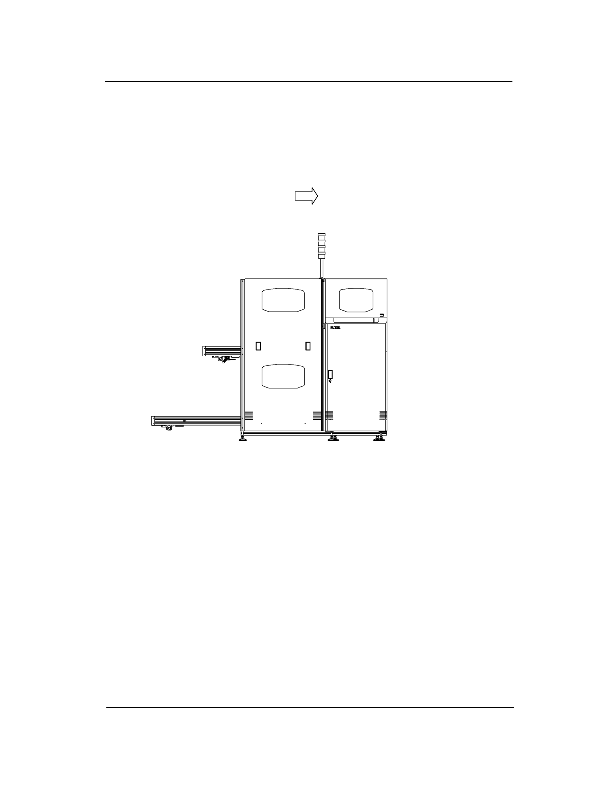
MULTI
MAGAZINE
LINE
LOADER
NTM110LL-HW

NUTEK PTE LTD
In the compilation of this manual, attention has been given to
avoid errors and mistakes in an attempt to provide a clear
structure to the content.
In spite of this, errors cannot be completely avoided.
If in going through this manual should you:
- discover incorrectness
- encounter unclear statements
- meet with parts that in your opinion needs further explanation,
please inform us. We will appreciate any comments which will
help us to improve this document.
For corrections or clarification, please contact:
Address: NUTEK PTE LTD
39 Joo Koon Circle
Singapore 629105
Tel: (065) 6862-0255
Fax: (065) 6862-0040
Internet Address: http://www.nutek-sg.com

Machine Name:
Multi magazine line loader, L-size
Job Description: NTM110LL-HW
Job No: 2010-0633A01
Voltage: 230 Vac
Phase: 1
Power Consumption: 350 VA Max
Product: PCB
Product Size: L - 70.00~407.00 mm (W) / 80.00~457.00 mm (L)
Product Edge Clearance: 3 mm
Product Thickness: 0.60 ~ 1.60 mm
Component Height: Top: 30 mm (Max) Below: 30 mm (Max)
Transfer Height: 950 (+/- 25mm)
Weight: 310 kg (Approx.)
Air Pressure: 4-6 bars
Machine Colour: RAL 9002 (8093A)
Direction: L to R
Magazine Type / Model: NKAJ-0525R / CAB 716
Noise Level: < 70 dBA
* Please refer to 3D drawing for physical dimension.
Fix Rail: Front
1.0 INTRODUCTION
Machine specification1.1

Membrane Multi Magazine Line Loader
Teeth Type
Standard
1.2 Terms of Reference
The following list some of the terms that could be used in this Manual.
PCB − Printed Circuit Board,
Magazine − Container that holds the PCBs,
Transfer of PCB − The process in which the PCB is transported between
machines,
Load/Loaded − The process in which the PCB is transferred from the
magazine into the production line,
Transfer height/
PCB height
− Board flow height from the floor level,
Pitch − Distance between two slots in the magazine (usually
10mm),
Index/Indexing − The distance in which the magazine is raised or
lowered per request,
Full magazine − Magazine that contains PCB (either full or partially
full),
Empty magazine − Magazine that is completely empty,
Slot 1 − The lowest slot of the magazine.
Slot 50 − The highest slot of the magazine.
Downstream
Board
Available (DBA)
− A signal sent from Nutek machine to the Downstream
machine to inform the availability of a PCB at Nutek
machine;
Downstream Busy
(DSB)
− A signal sent from the Downstream machine to Nutek
machine to confirm ready to receive a PCB from
Nutek machine.

Membrane Multi Magazine Line Loader
Teeth Type
Standard
1.2.1 Abbreviation Use in Manual
Abbreviation Description
BK Brake
BZ Buzzer
C Capacitor
CN Connector
CS Curtain Sensor
CYL Cylinder
D Diode
DBA Downstream Board Available
DSB Downstream Busy
E Earth
EM Emergency Switch
F Fuse
FS Foot Switch
H Indicator light
INV Inverter
K Relay
LS Limit Switch
M Motor
MCB Main Circuit Breaker
N Neutral
OL Overload Relay
PB Push Button
PCB Printed Circuit Board
PHS Photo Sensor, Gap Sensor
PS Power Supply
RS Reed Switch
SV Solenoid Valve
SW Switch
TB Terminal Block
TP Terminal Point
UBA Upstream Board Available
USB Upstream Busy

Membrane Multi Magazine Line Loader
Teeth Type
Standard
1.2.2 Label Definition
Label Description
Danger! High Voltage! Do not detach
the protective covers. Operating this
equipment without covers may cause
electric shock.
Do not touch the equipment while it is
running. Working near moving
machinery or live parts may result in
electrocution or getting entrapped in
machine.

Membrane Multi Magazine Line Loader
Teeth Type
Standard
1.2.3 Safety Section
It is essential for the operator to understand how the machine functions before
he/she handles the machine. Understanding the machine will help to create an
awareness of the machine’s capability & limitation which play an important role in
safety. Below are the recommended sections to read in order to be familiarized
with the machine.
i. Expected use and Limit of use (Section 1.3)
ii. Machine Functions (Section 2.0)
iii. Switches Function & Description (Section 6.0)
iv. Operating Conditions & Machine Sequence (Section 5.0 & 7.0)
In addition, if the operator requires to adjust or calibrate the machine to cater for
product changes, please refer to Installation & Calibration (Section 3.0 & 4.0).
Note: Always switch off the power supply before opening any protective cover
over an electrical circuit.

Membrane Multi Magazine Line Loader
Teeth Type
Standard
1.3 Expected use and limit of use
1. This machine is intended for loading PCB from the magazine to the
production line or another machine.
2. This machine is not intended to be a standalone unit. It must always be
installed beside a machine with integral covers or guards at the vicinity of
its opening for a PCB transfer (see fig.1).
3. During production, this machine operates under Auto mode with no
operator intervention except for putting filled magazine/s onto the lower
Conveyor and removing empty magazine/s from the upper Conveyor.
4. This machine is intended for used with the specified magazine only (see
section 1.0). The type and size of the PCB that can be handled by this
magazine is specified by the manufacturer or the supplier.
5. This machine is intended for use in an industrial environment that is well
ventilated, clean and dry with the maximum humidity at 90% and the
temperature range from 150C to 350C.
6. This machine is intended for both air and electrical supplies stated on the
specification (see section 1.0).
7. This machine is designed for a lifespan of 7 years with adequate
maintenance and replacement of worn parts.
8. Before start-up, the operators are expected to have read and understood the
safety section (see section 1.2.3) of the instruction manual that
accompanies the machine, and to be familiar with the location and
operation of each control.

Membrane Multi Magazine Line Loader
Teeth Type
Standard
FLOW CONFIGURATION FOR MULTI MAGAZINE LINE LOADER
Direction of PCB Flow
Fig 1

Membrane Multi Magazine Line Loader
Teeth Type
Standard
2.0 Machine Functions
The Loader is divided into three main assemblies:
1. Lifter
2. Input (Lower) Conveyor
3. Output (Upper) Conveyor
2.1 Lifter
The Lifter accepts a full magazine from the Input (lower) Conveyor. It will index
upwards until Slot 50 (for Pitch 1), Slot 49 (for Pitch 2), Slot 48 (for Pitch 3) or
Slot 47 (for Pitch 4) of the magazine is at the transfer height. Upon receiving a
Downstream Busy (DSB) signal, it will load a PCB onto the Downstream machine.
Loading is done by means of a pusher cylinder assembly located inside the Output
(upper) Conveyor. The Lifter will index upwards until the next slot of the
magazine is again at the transfer height.
The loading process repeats until the last PCB in the magazine is transferred out.
The empty magazine will be brought to the highest position and transferred onto
the Output (upper) Conveyor.
2.2 Input (Lower) Conveyor
The Input (lower) Conveyor allows a full magazine to be placed at its entrance and
transfer it over to the Lifter assembly. It can accept and hold up to three
magazines. Stoppers are used to provide separating action, allowing only one
magazine to be transferred onto the Lifter. Cam switches or sensors are used in
conjunction with the stoppers.
2.3 Output (Upper) Conveyor
The Output (upper) Conveyor receives the empty magazine from the Lifter. It can
accept and hold up to two magazines.

Membrane Multi Magazine Line Loader
Teeth Type
Standard
3.0 Installation
3.1 Pre-installation
The following list the general procedures before installation:
− Ensure that the space catered for is sufficient;
− Connect the power supply and air supply (ensure that the supplies are within
the specifications of the machine);
− Place one magazine (that contains some PCBs) onto the Input Conveyor;
− Power up the machine and switch to Auto mode. Allow the magazine to reach
the transfer height;
− Adjust and level the machine to the desired loading height by the six footing
(the machine allows for a levelling of ± 30mm);
− Disconnect the power and air supply.
The machine is now ready for installation.
Note: This machine is allowed a levelling adjustment of ± 30mm. However, problems
may arise during the installation and levelling if the discrepancy between the
specified and desired height is more than 15mm.

Membrane Multi Magazine Line Loader
Teeth Type
Standard
3.2 Installation
The following list the general procedure, during installation:
− Place the machine into the required position while ensuring correct orientation.
(The loader is usually placed at the beginning of the production line);
− Connect the power and air supply. The interface between the Loader and the
Downstream machine is to be connected after the installation;
− Switch the machine to Manual mode;
− Clamp the magazine;
− Index the Lifter until the Slot 49 of the magazine is at the transfer height
position;
− Align the machine by adjusting the position and the footing. (See 3.3 for the
procedure used by Nutek);
− After confirming the alignment, test by depressing the PUSHER membrane
switch to activate the pusher;
− Align the magazine by adjusting the 2 magazine clamps at the top of the
support bridge (see 3.5 for the procedure);
− Ground the machine either by raw bolt or by link-plate as required.
The machine is now installed.

Membrane Multi Magazine Line Loader
Teeth Type
Standard
3.3 Alignment of Machines
There are many ways of aligning two machines. Nutek makes use of two similar
PCBs and the general procedure is as follows:
− Place a PCB on the Conveyor as shown in figure 1a;
− Adjust the Conveyor until the angular misalignment and the offset is minimum;
− Adjust the height so that the Upstream machine is slightly higher than the
Downstream machine as shown in figure 1b;
− Test the alignment with the PCBs and repeat the steps again if necessary.
The machine is now aligned.

Membrane Multi Magazine Line Loader
Teeth Type
Standard
3.4 Handling
A The following list the general guidelines on the production floor
(Refer to Figure 1c):
− The machine can be handled by a pallet truck.
− A short length of wood (about 50mm x 50mm) long enough to rest
securely across the fork of the truck (more than 600mm in length).
− Insert the pallet truck under the machine as shown; a piece of wood
would help to absorb the height difference at the bottom.
− A trolley could be used instead of the wooden support beam to give
better support especially for the LL size machine.
B The following list the general handling guidelines when using the forklift:
− As the machine is constructed from aluminium profiles, it must be
handled with care to prevent damage to the machine through rough
handling.
− A short length of wood about 2" square and about 600mm must be
used.
− Ensure that the fork could reach the entire width of the machine.
Fig.1c

Membrane Multi Magazine Line Loader
Teeth Type
Standard
3.5 Alignment of Magazine
Magazine alignment is carried out after machine alignment. The procedures are as
follows (refer to figure 1d):
− Load in a magazine, preferably a reference magazine, onto the machine;
− Allow it to transfer onto the Lifter in Auto mode;
− Switch the machine to Manual mode;
− Clamp the magazine;
− Index the Lifter until Slot 1 of the magazine is at the transfer height;
− Check the magazine alignment with the two PCBs method (see section 3.3);
− Loosen all mounting fixtures that hold the machine is at the transfer height;
− If adjustment is necessary, release the magazine and loosen the two reference
clamping cylinders/ guiding bracket at the top of the bridge support;
− Clamp the magazine again and adjust the reference cylinders to align the
magazine. Check for both angular and offset misalignment;
− Tighten the reference cylinder/bracket;
− Check that the magazine top clamp can engage the magazine properly during
clamping operation;
− Test the setting by using the pusher (PUSHER membrane switch) to check the
transfer of the PCB;
− Confirm the setting with other magazines and fix the mounting.

Membrane Multi Magazine Line Loader
Teeth Type
Standard
Fig.1d

Membrane Multi Magazine Line Loader
Teeth Type
Standard
4.0 Calibration & Adjustment
Caution: Ensure that the correct magazine racks are used with its width
correctly adjusted and properly positioned on the machine.
4.1 Width Adjustment
A removable crank is provided for Input (Upper), Output (Lower) and Lifter
Conveyors' width adjustment. Clockwise rotation reduces the width and vice versa.
Remove and keep the crank during operation to avoid accidental width change.
LOCATION OF WIDTH ADJUSTMENT FOR
LIFTER CONVEYOR
LOCATION OF WIDTH ADJUSTMENT
FOR INPUT & OUTPUT CONVEYORS
Width adjustment here

Membrane Multi Magazine Line Loader
Teeth Type
Standard
4.2 Pusher Adjustment
This is done whenever the width of the PCB is changed.
Cautions: Before any adjustment, the adjacent equipment must be stopped or
even powered down. Ensure that the machine is in the transfer
position.
− Load in a magazine, preferably a reference magazine, onto the machine;
− Allow it to transfer into the Lifter in Auto mode and index until the Slot 1 of
the magazine is at the transfer height;
− Depress STOP followed by MANUAL membrane switch to switch the
machine to Manual mode;
− Remove the cover of the top Conveyor;
− Loosen the two clamp levers located at the pusher cylinder brackets;
− Slide the cylinder assembly until it is along the centre of the PCB;
− Check that the pusher cylinder is parallel to the magazine and tighten the
clamp levers;
− Depress PUSHER membrane switch to test;
− Confirm the setting.

Membrane Multi Magazine Line Loader
Teeth Type
Standard
4.3 Magazine number of slot requirement
The Loader is factory set to use the reference magazine from Slot 1 to Slot 50. If
this setting has to be changed, please note the following steps (Refer to figure 1e):
− Load in a magazine, preferably a reference magazine, onto the machine;
− Allow it to transfer into the Lifter in Auto mode;
− Switch the machine to Manual mode;
− Clamp the magazine;
− Index the magazine until the required slot (e.g. Slot 50) is at the transfer
height;
− Turn off the power supply;
− Adjust the teeth sensor plate so that the lowermost teeth of the teeth
sensor plate is aligned with Slot 50 of the magazine;
− Power up the machine and test the adjustment by indexing in the
Manual mode, making sure that the sensor and the sensor plate does not
crash during indexing;
− Index the Lifter until Slot 1 of the magazine is at the transfer height and
adjust the Last Pitch sensor above the indexing sensor plate;
− Confirm the slot setting with other magazine by operating under the
Auto mode.
Table of contents