Raytools BM114S Series User manual

BM114S SERIES
6KW Auto-Focusing Laser Cutting Head- User Manual
Email: sales@raytools.net
Add: EMMENTALSTRASSE 96 CH-3414 OBERBURG, SWITZERLAND

1 | 29
www.raytools.net
BM114S SERIES 6KW Laser Cutting Head User Manual
Historical Version:
History
version
Date
Change the profile
Editors
Reviewers
Review date
V1.0
2018/10/12
Establish BM114S User
Manual
Walter Fan
2018/10/12
Alex Li
Thank you for choosing our product!
This manual makes a detail introduction about the use of BM114S laser cutting head, including
installation, setup, operation and service etc. Please directly contact us if you have other things to
know.
Please read these instructions carefully before use the series cutting head and relative equips.
This will help you to use it better.
Because the product keeps renewing, please note the product you receive may differ slightly
from the illustrations in this manual in some aspects. We apologize for your inconvenience here.
Version
V1.0
Date:
2018/10/12

2 | 29
www.raytools.net
BM114S SERIES 6KW Laser Cutting Head User Manual
Index
1Summary..................................................................................................................................4
1.1 Product Advantages...............................................................................................................4
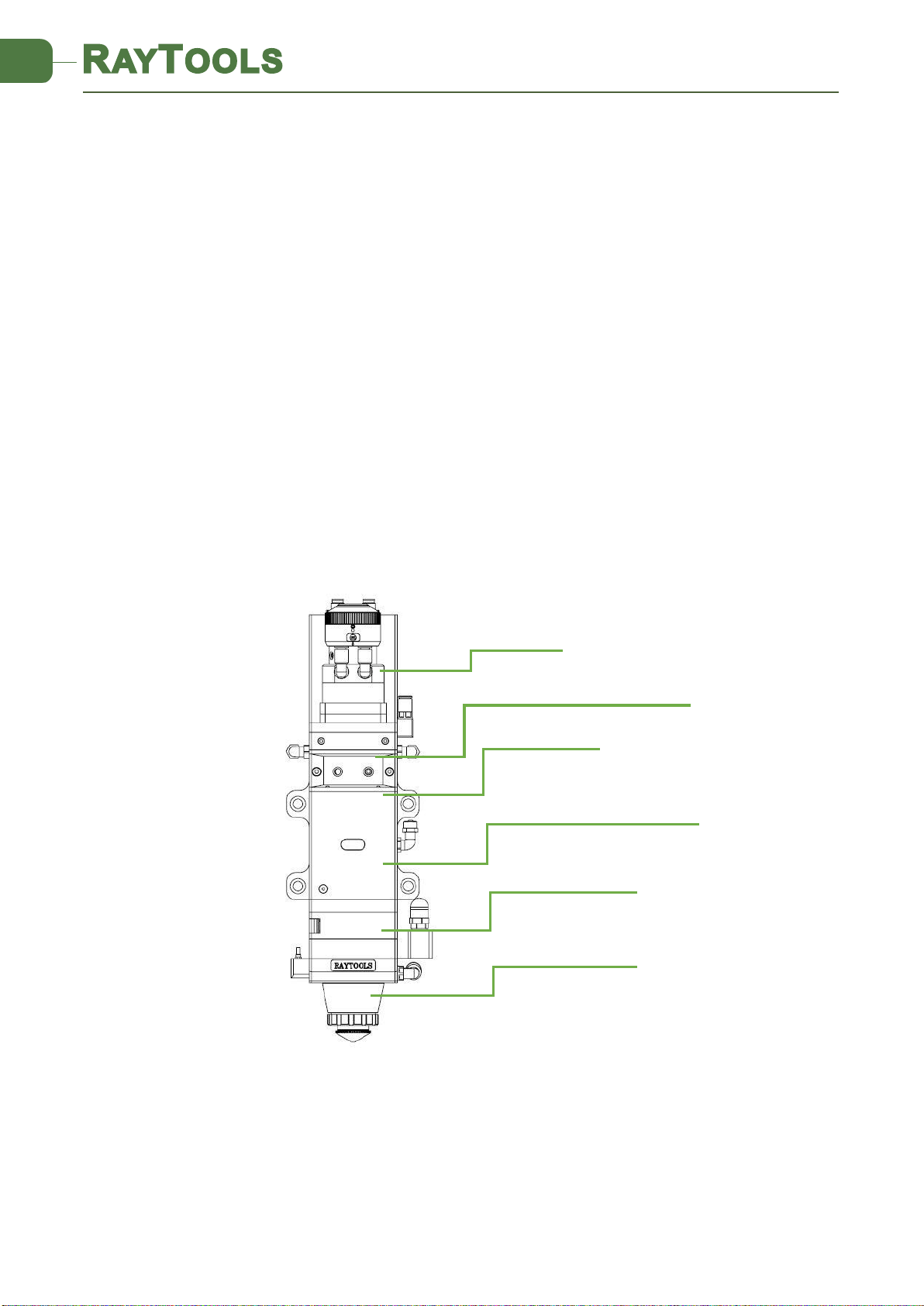
1.2 Structure & Function .............................................................................................................5
2Machinery Installation .............................................................................................................6
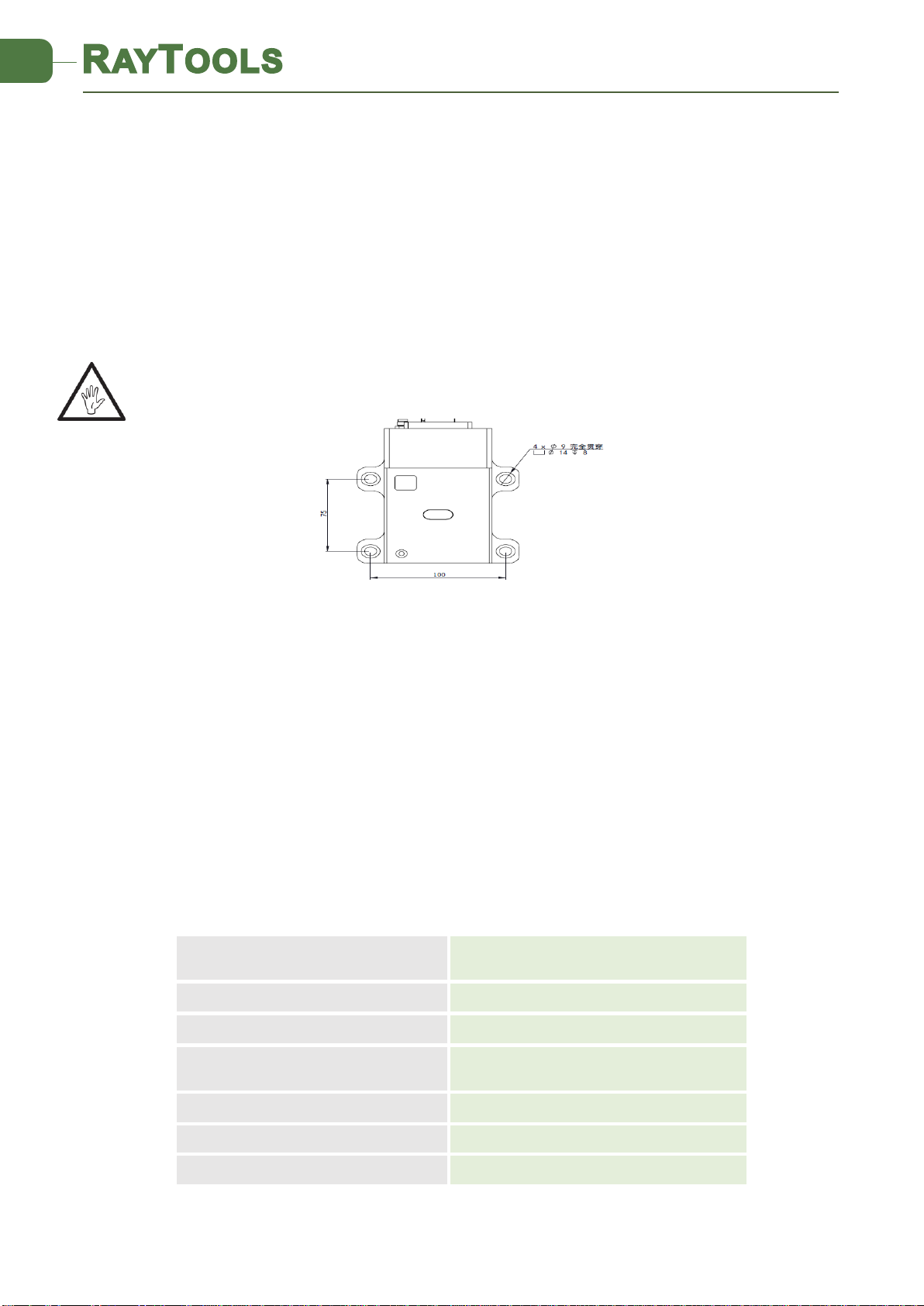
2.1 Mounting ...............................................................................................................................6
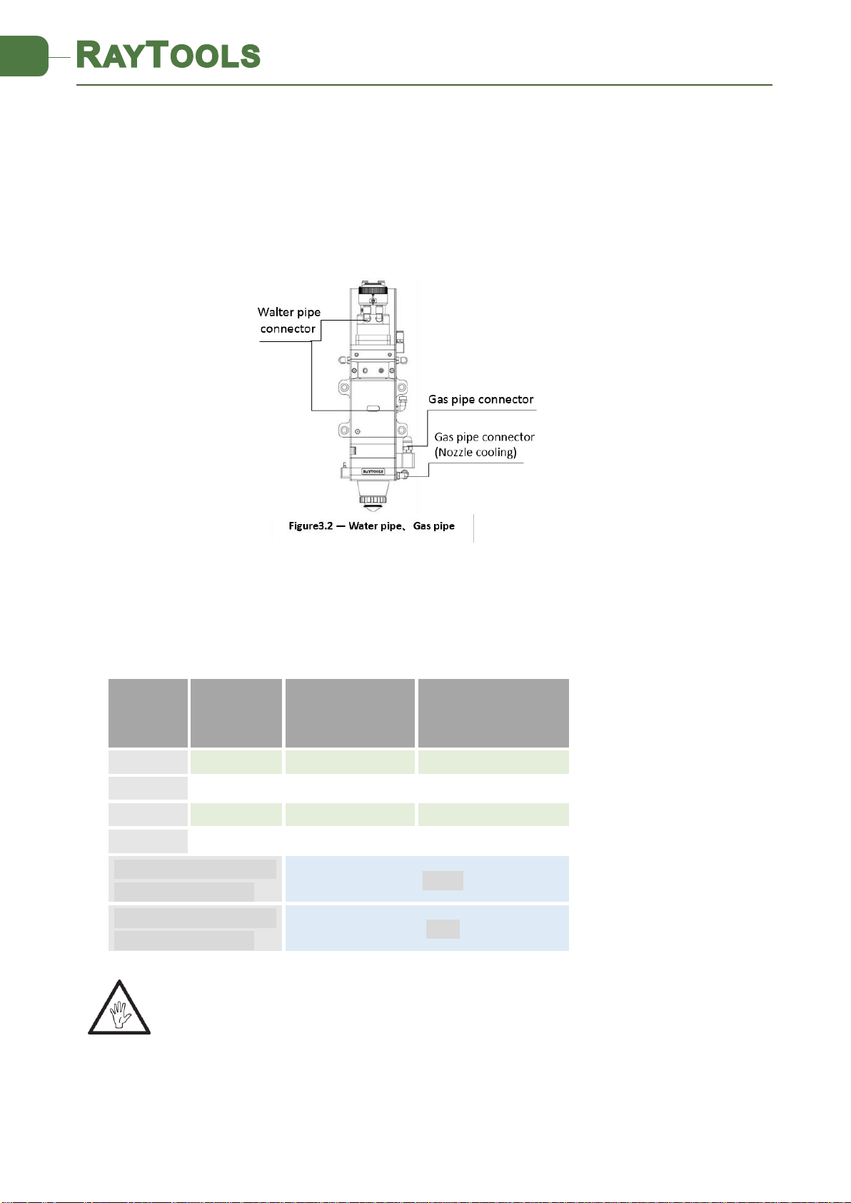
2.2 Connection of Water Pipe and Gas Pipe ...............................................................................6
2.2.1 Water-cooled interface.........................................................................................6
2.2.2 Assist gas interface ...............................................................................................7
2.3 Connection of Cutting Head Cable ........................................................................................8
2.3.1 Connection of Cutting Head and Cable ................................................................8
2.3.2 Cable connection and drive connection...............................................................8
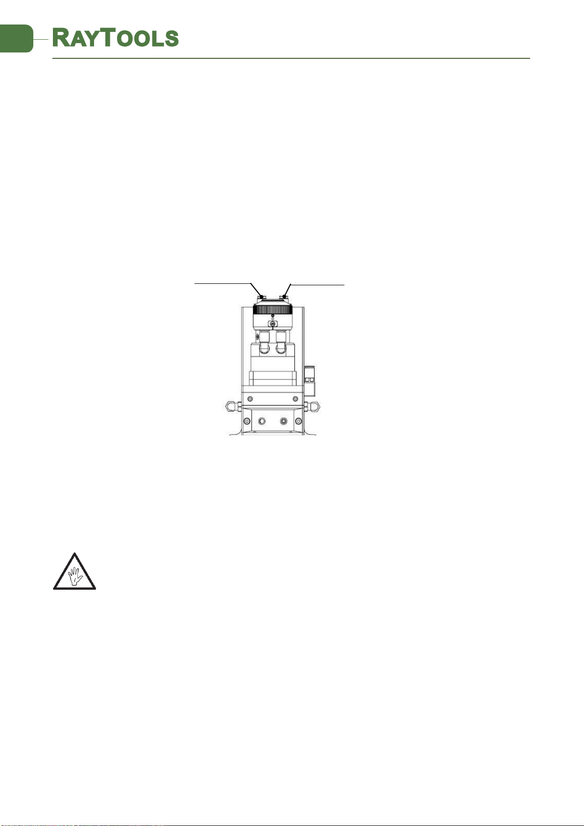
2.4 Fiber Input Interface..............................................................................................................8
2.5 Fiber Insertion and Interface Direction Adjustment .............................................................9
3System Installation Commissioning .......................................................................................10
3.1 ETC_F100 Installation ..........................................................................................................10
3.1.1 Interface & Signal ...............................................................................................10
3.1.2 Wiring .................................................................................................................12
3.1.3 Dimension of ETC_F100......................................................................................13
1.1 Figure 4.3 —Overall size of ETC-F100 controller (unit: mm)...............................................13
3.1.4 Dimension of Drive.............................................................................................14
3.2 FSCUT (BC) with position mode...........................................................................................14
3.2.1 Wiring .................................................................................................................14
......................................................................................................................................15
3.2.2 Interface Operation ............................................................................................16
3.3 FSCUT (BC) with velocity mode ...........................................................................................16
3.3.1 Wiring .................................................................................................................16
3.3.2 Software settings................................................................................................17
3.3.3 Interface Operation ............................................................................................18
4Beam Adjustments and Focusing...........................................................................................18
4.1 Beam Adjustments (QBH interface) ....................................................................................18
4.2 The Focus Position Adjustment ...........................................................................................19
5Maintenance.......................................................................................................................... 20
5.1 Cleaning Lens.......................................................................................................................20
5.2 Removal and Installation of Lenses .....................................................................................20
5.2.1 Removal and Installation of Collimating Protective Lenses ...............................20
5.2.2 Removal and Installation of Collimating Lenses.................................................21
5.2.3 Removal and Installation of Collimating Lenses.................................................22
5.2.4 Removal and Installation of Focus Lenses..........................................................23

3 | 29
www.raytools.net
BM114S SERIES 6KW Laser Cutting Head User Manual
5.3 Replace Nozzle Connector...................................................................................................24
5.3.1 Replace Ceramic Body ........................................................................................24
5.3.2 Replace Nozzle....................................................................................................24
5.4 Troubleshooting of Driver....................................................................................................25
5.4.1 Alarm information ..............................................................................................25
1、Up or Down Limit Alarm ........................................................................................25
2、Home first ..............................................................................................................25
3、Exceed Z-axis Travel................................................................................................25
4、Servo Alarm............................................................................................................25
5.5 Common Problem Analysis..................................................................................................26
5.5.1 Servo calibration process terminated abnormally .............................................26
5.5.2 The screen is abnormally displayed ...................................................................26
5.5.3 Z-axis coordinate drift.........................................................................................26
5.5.4 Input signal jitter or invalid ................................................................................26
6Mechanical and Optical Configurations Diagram ..................................................................27
6.1 Cutting Head Shape.............................................................................................................27
27
6.1.1 Focus length .......................................................................................................29

4 | 29
www.raytools.net
BM114S SERIES 6KW Laser Cutting Head User Manual
1Summary
This manual covers the general description of BM114S series products, including the basic
installation, factory settings, operation, use and maintenance services and other aspects. The
specific Optical mechanical customization configurations are too much, so only the main unit
parts will be introduced in this manual.
The BM114S series is an automatic focusing fiber cutting head released by Swiss RAYTOOLS
AG in 2018. The product is equipped with internal servo motor and internal driver units, which
can drive the focus lamp to change position automatically in the range of about 25mm by linear
mechanism. Users can continuously focus through setting program to finish the rapid perforation
of thick plates and the automatic cutting of plates of varies thickness and material. The product
can be equipped with D37 composite lens group to integrate the beam, a variety of interface
settings, so that it can be used with a variety of fiber lasers; optimized optical and water-cooled
design allows the laser head work under high power steadily for a long time.
1.1 Product Advantages
QBH interface
Collimating module
Base module with focusing system
Protective lens module
Cutting nozzle module
Collimating protective lens module
Fig 1 - laser head structure

5 | 29
www.raytools.net
BM114S SERIES 6KW Laser Cutting Head User Manual
Optimized optical configuration and smooth and efficient airflow design;
Automatic focusing range + 10 ~ -15mm, adjustment accuracy 0.05mm;
Equipped with D37 composite lens, the maximum fiber input power can carry 6KW;
Maximum acceleration of focus lens driver 10m / s2, maximum speed 10m / min;
The drawer type lens holder make the replacement of protective lens more quickly and
easier
The composite lenses were used for collimation and focusing to obtain the best optical
quality and cutting effect;
Equipped with QBH, QD and other fiber interfaces can match with various fiber lasers.
1.2 Structure & Function
As shown in Figure 1, the laser head consists of four basic units, such as collimating
module CM, focusing driving module, protective lens module and nozzle module.
Collimating module: The collimation function of the optical fiber is collimated after the
incident laser is collimated into a parallel beam and the function of tuning;
Focusing driving module: The collimated beam is focused into a concentrator beam with
high power density, and the focus position is automatically adjusted by the driving device;
Protective lens module: the protective lens protects the focusing lens from damage by
returning the slag and prolongs the service life of the focusing lens;
Nozzle module: Guide the focus beam to the work piece and produce high velocity jet
cutting to achieve high quality cutting

6 | 29
www.raytools.net
BM114S SERIES 6KW Laser Cutting Head User Manual
2Machinery Installation
2.1 Mounting
BM114S laser machining head and the fixed mounting hole size and position of the machine
tool are shown in Figure 3.1. Customers are advised to Install the laser head perpendicular to
the machined surface as requested and make sure the laser head is locked, which is one of the
premises to ensure the follow up sable cutting effect.
CAUTION: The Z-axis sliding base for fixing laser processing head should be connected with
machine tools and keep a good grounding.
2.2 Connection of Water Pipe and Gas Pipe
2.2.1 Water-cooled interface
BM114S laser processing head has 3 sets of water-cooled channels which direction of water
entry and exit can be arranged arbitrarily. It is important to note that when the laser power is
greater than 500 watt, it is recommended to use water-cooled.as you can see from Figure 3.2,
the position and amount of the water interface, and the right table details the recommended
flow velocity.
The design of this water-cooled interface is closed loop water-cooled system, and it also can
be used equipped with external water supplied but subjected to the requirements of the list.
Outer diameter of water
pipe caliber
6mm
Minimum flow speed
1.8 l/min(0.48gpm)
Entry pressure
170-520kPa(30-60 psi)
Entry temperature
≥room temperature />dew
point
Hardness (relative to CaCO3)
<250mg/liter
PH range
6 to 8
Particles size available
Diameter less than 200 microns
Figure 3.1 — Mounting

7 | 29
www.raytools.net
BM114S SERIES 6KW Laser Cutting Head User Manual
2.2.2 Assist gas interface
The impurity in assist gas such as hydrocarbon and steam will damage the lens and cause
cutting power fluctuation as well as inconsistencies between the sections of the work piece. The
firm below is the recommended auxiliary gas specification. The higher the purity of the gas, the
better the quality of the cutting section.
Impurity can be filtered out in gas supply tube, but Oxygen and water vapor can permeate
light path through nonmetal materials, which is the source of the appearance of dust and
hydrocarbon. Stainless steel fittings are recommended, at the same time must use filters which
can remove a minimum of 0.01 micron particle to purify.
A pressure gauge with a stainless steel diaphragm is recommended. Industrial pressure
gauges suck in air. Rubber diaphragm produce hydrocarbon by aging or other factors.
CAUTION: Gas interface cannot be replaced arbitrarily, especially do not use PTFE TAPE,
Otherwise, the gas path will be blocked, the normal cutting will not be possible and
the laser head parts will be damaged at the same time.
Gas
Purity
Maximum
content of water
vapor
Maximum content of
hydrocarbon
oxygen
99.95%
<5 ppm
<1 ppm
nitrogen
99.99%
<5 ppm
<1 ppm
argon
99.998%
<5 ppm
<1 ppm
helium
99.998%
<5 ppm
<1 ppm
Diameter of auxiliary gas
pipe (Outer diameter)
10mm
Diameter of cooled gas
pipe (Outer diameter)
8mm

8 | 29
www.raytools.net
BM114S SERIES 6KW Laser Cutting Head User Manual
2.3 Connection of Cutting Head Cable
This paper mainly introduces the connection between the cable and the cutting head. The
control section of the driver and the connection refer to the wiring diagram of each series of
system.
2.3.1 Connection of Cutting Head and Cable
Connect the corresponding connector of cutting head with motor power cable, encoder
cable, sensor cable respectively (as shown in figure 3.3). After the proper length is reserved, the
cable is inserted into the track groove of the machine tool and fixed.
2.3.2 Cable connection and drive connection
Connect motor power wire and encoder wire with the corresponding interface of driver
according to the definition in cable sleeve.
CAUTION: The output signal of limiting sensor is NPN-NC;
CAUTION: All wiring is in the state of power failure, and the power can be debugged after
inspection
.
2.4 Fiber Input Interface
BM114S is suitable for most industrial laser generators. It is equipped with collimator.
The connection between the end of the fiber and the cutting head is called fiber interface.
Commonly used fiber connectors include QBH, QD, etc, and every fiber interface has its unique
fixation method. Please refer to corresponding instruction of fiber interface. Figure 3.4 shows
the installation interface of QBH connector.
Figure 3.3 — Cable interface of laser head
Power line
Encoder line

9 | 29
www.raytools.net
BM114S SERIES 6KW Laser Cutting Head User Manual
WARNING: The optical devices must be kept clean and all dust must be removed before
use. If the laser head is vertically inserted in the optical fiber, the laser head must be
rotated 90 degrees to the horizontal level and then inserted into the optical fiber to
prevent dust from entering the interface and falling on the surface of the lens. Upper limit
in the fiber before fixing the laser head.
2.5 Fiber Insertion and Interface Direction Adjustment
In this paper, an optical fiber insertion method is described in conjunction with a QBH joint.
First, align the red point at the end of the QBH interface with the red point of the handwheel;
then remove QBH dust proof cover and the red mark of fiber output end is aligned QBH red
mark and insert straight to bottom; Then turn the QBH handwheel clockwise. It is in place when
you hear the "Da" voice, then pull the handwheel up and turn clockwise again. (see Figure 3.4)
When the fiber connector is inserted into the interface, if the red dot on fiber is too far
away from the red dot on laser head interface, causing an out of alignment insertion, you can
refer to steps below to adjust the position of fiber interface on laser head for solving the problem.
As shown in Fig. 3.4, unscrew the 4 locking screws of the position of the part icon with a wrench,
rotate the QBH interface and screw the locking screws after the red mark is in place.

10 | 29
www.raytools.net
BM114S SERIES 6KW Laser Cutting Head User Manual
3System Installation Commissioning
3.1 ETC_F100 Installation
3.1.1 Interface & Signal
Interface
Descriptions
CON1
DB15 female connector, interface to servo driver.
CON2
Interface for connecting external IO devices.
CON3
Interface to 24V DC power supply.
CON4
Interface for connecting external IO devices.
Pins of CON1:
Pin
Descriptions
1
OUT_Servo_DA(Drive speed command)
2
Servo_TGON(Drive brake signal)
3
Servo_CLR(Drive alarm clear signal)
4
Servo_OS(Drive zero speed clamp, used to control motor lock
shaft)
5
PGND(Power ground)
6
E1_A_N(Encoder A negative)
7
E1_B_N(Encoder B negative)
8
E1_C_N(Encoder C negative)
9
AGND(Analog ground)
10
Servo_ALM(Drive alarm signal)
11
Servo_SON(Drive enable signal)
12
VDD_24V(Power supply)
13
E1_A_P(Encoder A positive)
14
E1_B_P(Encoder B positive)
15
E1_C_P(Encoder C positive)

11 | 29
www.raytools.net
BM114S SERIES 6KW Laser Cutting Head User Manual
Pins of CON2:
Pin
Descriptions
N/A
/
N/A
/
Alarm out
When alarm occurs, a high level signal is output, normally is high
impedance state.
Home
Homing input signal, active high.
AGND
Common ground of analog signals, analog signals include: focus set
input, focus feedback output.
Focus set
The input signal of focus setting, is analog.
Focus
Feedback
Output the position of current focus, is analog.
Brake+
This signal is not connected (motor without brake)
Note:N / A is an undefined interface, please leave it blank.
Pins of CON4:
Pin
Descriptions
Emergency
Stop
When the accident occurs, press the emergency stop button to achieve
emergency stop, 24V effective.
N/A
/
Focus IN
Pos.
Output 24V when focus in position.
N/A
/
N/A
/
Focus
Enable
High-level control focus on, low-level control focus off.
Down limit
The input signal of down limit, NPN.
Up limit
The input signal of up limit, NPN.
Note:N / A is an undefined interface, please leave it blank.
The above table shows only for factory default settings for the ETC-F100 controller.

12 | 29
www.raytools.net
BM114S SERIES 6KW Laser Cutting Head User Manual
3.1.2 Wiring
The motor is an ac servo motor, which is connected with 220V AC L and N at the driver
terminals L1, L2, L1C and L2C. Details of connection method as shown in figure 4.1
Limit signal: the limit diagram is shown in figure 4.2.
Brown
White & Brown
Green
White & Green
+24V
0V
Up limit
Low limit
Note: the limit sensor is NPN-NC and it continuously outputs 0V signal when it is not
triggered.
Figure 4.1—ETC_F100 Wiring instruction

13 | 29
www.raytools.net
BM114S SERIES 6KW Laser Cutting Head User Manual
3.1.3 Dimension of ETC_F100
Figure 4.2—limit diagram
1.1 Figure 4.3 —Overall size of ETC-F100 controller (unit: mm)

14 | 29
www.raytools.net
BM114S SERIES 6KW Laser Cutting Head User Manual
3.1.4 Dimension of Drive
3.2
FSCUT (BC)
with position mode
3.2.1
Wiring
The motor is AC servo motor, which should connect the
end of the drive L1, L2
,
L1C and L2C
to
AC
220V L and N. Please refer to figure 4.5 for the wiring connection mode and figure 4.4 for
the driver installation size
Limit signal:As shown in figure 4.2
Brown White & Brown Green White & Green
+24V 0V Up limit Low limit
Note: The limit sensor is NPN-NC and it continuously outputs 0V signal when it is not
triggered.
Figure4.4 —Overall size of drive (unit: mm)

15 | 29
www.raytools.net
BM114S SERIES 6KW Laser Cutting Head User Manual
Open the platform configuration tool, enter the value shown in Figure 4.6
1. Set parameter as the figure (only for reference).
2. Select J axis for detection, open loop and initiate enable to travel and detect the encoder
in (-14mm~+10mm) to determine the encoder direction.
3. Save the parameters and enter the interface
Figure 4.6 — Platform configuration tools
Figure4.5 — Position loop FSCUT wiring diagram
Focus range was updated to "-20mm to 15mm" for
BM114S which was produced since Jan of 2020

16 | 29
www.raytools.net
BM114S SERIES 6KW Laser Cutting Head User Manual
3.2.2 Interface Operation
1. Move J axis to check if the action is normal (“thread pitch” and direction), J+ indicates
scale 0+.
2. Slowly moving the J axis so that it meets the positive and negative limit, check whether
the direction and limit signal are normal or not.
3. By click homing icon, J axis moves to negative direction and do 2nd homing when touches
negative limit. In this case the position of zero point coincides with zero focal position.
The homing is finished.
Brown White & Brown Green White & Green
+24V 0V Up limit Low limit
Figure
4.7—
Operation
Note:
1.
Click+, the
lens holder
moves
upward. When it touches positive limit, click
-, then
lens
holder
moves
downward to the negative limit.
2.
The direction of origin is negative, and take
lower limit as a sampling signal.
3.
Pitch 2mm, 10000 pulses
per
turn
4.
Positioning speed
is
recommended 50-100mm/s.
3.3
FSCUT (BC)
with velocity mode
3.3.1
Wiring
1.
The motor is AC servo motor, which should connect the end of the drive L1, L2 , L1C and
L2C to
AC
220V L
and N. Please refer to figure 4.8
for the wiring connection mode and figure
4.4 for the driver installation size
2. Limit Signal:
As shown in
figure 4.1
interface

17 | 29
www.raytools.net
BM114S SERIES 6KW Laser Cutting Head User Manual
Note: The limit sensor is NPN-NC and it continuously outputs 0V signal when it is not
triggered.
3.3.2 Software settings
The axis parameter settings are shown in Figure 4.9. (only for reference)
Figure 4.8 — Velocity loop - FSCUT wiring diagram
Figure 4.9— Platform configuration
tools

18 | 29
www.raytools.net
BM114S SERIES 6KW Laser Cutting Head User Manual
Entry J axis detection, “closed loop and initiate enable”. Move J axis to see whether the action
is normal. Scale 0+ indicates J+. Check encoder and speed.
3.3.3 Interface Operation
1. Move J axis to check if the action is normal (“thread pitch” and direction), J+ indicates
scale 0+.
2. Slowly moving the J axis so that it meets the positive and negative limit, check whether
the direction and limit signal are normal or not.
3. By click homing icon, J axis moves to negative direction and do 2nd homing when touches
negative limit. In this case the position of zero point coincides with zero focal position.
The homing is finished.
Note:
1. Click+, the lens holder moves upward. When it touches positive limit, click -, then lens
holder moves downward to the negative limit.
2. The direction of origin is negative, and take lower limit as a sampling signal.
3. Pitch 2mm, 10000 pulses per turn.
4. Positioning speed is recommended 50-100mm/s.
4Beam Adjustments and Focusing
4.1 Beam Adjustments (QBH interface)
Cutting quality in a great extent depend on whether the lens is in the middle. If the lens is
not in the middle, the laser beam may contact with nozzle or inner wall to produce high
temperature deformation. Lens centering operation should be considered when nozzle is
replaced or the cutting quality is decreased.
Lens centering of laser cutting head can be finished by adjusting Collimating mirror, X-Y
direction. The adjusting screw is located on the top of the cutting head as shown in Figure 5.1.
Figure 4.10— Operation interface

19 | 29
www.raytools.net
BM114S SERIES 6KW Laser Cutting Head User Manual
By using inner hexagon spanner can loosen or screw the adjusting screw until the beam is located
in the middle of nozzle. Make sure the laser beam output from the center of nozzle. A method
commonly used tape dotting method:
Pick a scotch tape, flatten it, and attach it to the center of nozzle which directly below the
hole end face;
Open the inner guiding red light of the laser. Find and observe the position of nozzle center
that the red light in the scotch tape relative to;
Next open and adjust laser generator at the range of 80W-100W and dot manually.
Tear off the tape and check the hole in the center of the nozzle;
Repeat the above steps to find the optimum relative nozzle center position of the beam;
This adjustment requires a series of adjustments, which is the basic operation of general
laser tuning.
4.2 The Focus Position Adjustment
BM114S is equipped with automated focusing system. But it still need dot manually to redecide
the focus position when it reset of replacement of lenses, lasers. For details about operating
system parameters, please refer to the system instructions.
Manual focus can refer to the following steps:
1. The laser head scale is displayed to the maximum, and the laser power range is set to 80-
100w;
2. Then, within each moving 0.5mm (as small as possible), open a laser hole on the textured
paper;
3. Drilling several times, finally compare and find out the scale corresponding to the
smallest hole is zero coke, that is, the focus is just at the end of the nozzle section.
Table of contents
Other Raytools Industrial Equipment manuals
Popular Industrial Equipment manuals by other brands

NEXCOBOT
NEXCOBOT NEIO Series user manual

INSTROTECH
INSTROTECH 4001 operating manual

RUD
RUD VWBM quick start guide

OPW
OPW PetroVend M1700-SUN-FSC3000 General Installation, Operation and Maintenance Instructions

Climax
Climax H&S TOOL SPEED FACER ODF30 operating manual

TDI
TDI XBL Series Operation & programming manual