NuAire Haven HTS User manual

1
08. 04. 21. Document Number 671971
Nuaire | Western Industrial Estate | Caerphilly | CF83 1NA | nuaire.co.uk
HTS / HTE
Haven Terminal System
Installation Manual
1.0 SAFETY INFORMATION
• This equipment should not be used by children or persons with reduced physical, sensory or
mental capabilities or lack of experience and knowledge, unless they have been given supervision
or instruction concerning the safe use of the appliance by a person responsible for their safety.
Children shall not play with the appliance. Cleaning and user maintenance shall not be carried
out by children.
• Precautions may also need to be taken to protect the surrounding area from falling dust during
maintenance.
1.1 Symbols
REFER TO INSTRUCTION MANUAL
Read and understand the installation and maintenance manual before installing,
operating or maintaining this product.
1.2 Important Information
This manual contains important information on the safe and
appropriate assembly, transport, commissioning, operation,
maintenance, disassembly and simple troubleshooting of the product.
While the product has been manufactured according to the accepted
rules of current technology, there is still a danger of personal injury or
damage to equipment if the following general safety instructions and
the warnings contained in these instructions are not complied with.
•Read these instructions completely and thoroughly before
working with the product.
•Keep these instructions in a location where they are accessible
to all users at all times.
•Always include the operating instructions when you pass the
product on to third parties.
1.3 Personal Protective Equipment
The following minimum Personal Protective Equipment (PPE) is
recommended when interacting with Nuaire product:
•Protective Steel Toed Shoes - when handling heavy objects.
•Full Finger Gloves (Marigold PU800 or equivalent) - when
handling sheet metal components.
•Semi Fingerless Gloves (Marigold PU3000 3DO or equivalent)
- when conducting light work on the unit requiring tactile
dexterity.
•Safety Glasses - when conducting any cleaning/cutting operation
or exchanging filters.
•Reusable Half Mask Respirators - when replacing filters which
have been in contact with normal room or environmental air.
These products require installation work at ceiling level and require
access to ceiling voids for installation. Suitable precautions should
therefore be taken both for working at height, and for interaction with
the contents of the ceiling void.
Nuaire would always recommend a site specific risk assessment by a
competent person to determine if any additional PPE is required.
2.0 INTRODUCTION
The Haven range is a comprehensive collection of equipment that,
when used as part of a ventilation system, can create a healthy
environment in rooms within a commercial or other public building.
The essential concept is to deliver the correct amount of fresh supply
air locally to each occupant, and to extract vitiated air such that cross
contamination between occupants is minimised.
1 Typical Haven Terminal System

2
08. 04. 21. Document Number 671971
Nuaire | Western Industrial Estate | Caerphilly | CF83 1NA | nuaire.co.uk
HTS / HTEInstallation Manual
2.1 Code Description:
1 2 3 - 5
HT S 12 - PM1.80
1. Range: HT = Haven Terminal System
2. Airstream Type: S= Supply
E= Extract
3. Number Of Connections: 1= Single (Supply or Extract Equipment)
2 = Two (Extract Equipment Only)
3 = Three (Extract Equipment Only)
4 = Four (Supply Equipment Only)
9 = Nine (Supply Equipment Only)
12 = Twelve (Supply Equipment Only)
4. Filtration: PM1.55 = Particulate Filter (ePM1>55%)
PM1.80 = Particulate Filter (ePM1>80%)
E11 = E11 HEPA Filter
3.0 MECHANICAL INSTALLATION
Installation must be completed by competent persons, in accordance
with good industry practice and should conform to all governing and
statutory bodies i.e. IEE, CIBSE, etc.
These products require installation work at ceiling level and require
access to ceiling voids for installation. Suitable precautions should
therefore be taken both for working at height, and for interaction with
the contents of the ceiling void.
3.1 System Components
Other components may be required to complete the system – please
refer to Nuaire Ducting Specification Guide.
If adding Haven components to an existing system it is recommended
that the system is first cleaned by a BESA registered contractor, and the
system capacity and functionality verified.
3.1.1 Supply Terminals
•Single - HTS1 (See Section 3.2).
•Multiple - HTS4, HTS9, HTS12 (See Section 3.3).
2 Typical Single Supply Diffuser Installation
3 Typical Multiple Supply Diffuser Installation
3.1.2 Extract Terminals
•HTE1,HTE2,HTE3 (See Section X.X).
4 Typical Extract Terminal Installation
3.2 HTS1 Single Supply Terminal Installation
The terminal consists of a corrosion resistant steel housing with
directional distribution louvre and a connection port for a single 75mm
semi-rigid duct. A facia plate is also provided for finishing purposes.
5 HTS1 Single Supply Terminal Facia
6 HTS1 Single Supply Terminal Mounting Brackets
Alternatively, use the pre-tapped holes (M5) to fix to a prepared
mounting frame. M5 screws (by others) should not penetrate into the
housing beyond 25mm
The gap between the housing and ceiling cut-out should be fully sealed
with a proprietary low modulus, neutral cure mastic.
The semi-rigid ducting is installed by first locating the sealing ring
provided into the second complete groove in the duct outer surface.
Mark the semi-rigid duct at 50mm from the cut end, and push evenly
into the port aperture. When secure, close the port’s clip to retain the
duct. No further sealing of the connection is required or should be
applied.

3
08. 04. 21. Document Number 671971
Nuaire | Western Industrial Estate | Caerphilly | CF83 1NA | nuaire.co.uk
HTS / HTEInstallation Manual
8 HTS(4/9/12) Multiple Supply Terminal Installation 1
9 HTS(4/9/12) Multiple Supply Terminal Installation 2
Using the mounting brackets provided, secure the terminal housing to a
suitably rigid structure within the ceiling void.
The bracket fixing holes (4 no. M8) may also be used for alternative
fixing methods.
Attach rigid ducting to the terminal’s inlet spigot. Secure with self-
tapping screws, duct sealant and durable tape as required.
Ensure that the terminal is level, evenly supported and that the housing
is not distorted.
Additional connections to the terminal can now be made for optional
items if present, such as filter pressure tappings (HAVEN-PDIFF). Please
refer to documentation provided with those options.
Replace adjacent ceiling tiles / make good continuous ceiling to
terminal housing.
The directional louvres may be moved into the desired position at this
stage (if known to the installer).
10 HTS(4/9/12) Multiple Supply Terminal Duct Connections
7 HTS1 Single Supply Terminal Duct Connection
This duct type is largely self- supporting, and may be readily cut with
a hacksaw and manually formed into swept bends with a minimum
internal radius of approx. 150mm. Compact 90° bend components are
also available from Nuaire with similar sealed port design (product
code NRDD75-90).
For extended lengths of duct, supports with a maximum spacing of 1m
must be provided.
The duct must not be used to support the weight of the terminal
housing or other components. If the duct becomes kinked or crushed,
the affected section must be discarded and replaced.
Once the installation is complete, the facia plate may be attached to
the lower surface of the housing to obscure the cut edges of the ceiling
hole. Two M5 screw with caps are provided.
If required, the facia plate may be carefully trimmed to shape with
metal shears.
The directional louvre may be moved into the desired position at this
stage (if known to the installer).
3.3 HTS(4/9 /12) Multiple Supply Terminal Installation
The terminal consists of a corrosion resistant steel housing, with a
quantity of adjustable direction distribution louvres and a connection
spigot for a single 220 x 90 rigid duct. The terminal includes a fixed
flange trim, and (depending on model) may be fitted with a range
of filters and other accessories. A pair of mounting angle brackets is
provided.
In service, access to filters and internal ancillaries will be made via
a hinged, drop down panel at the lower face of the terminal. The
installation location should therefore allow an access space at least
600 x 600mm down to floor level directly below the terminal.
The terminal is primarily designed for installation into a suspended
ceiling grid but may also be used for a continuous ceiling installation.
Please note that full access to the ceiling void adjacent to the terminal
is required to complete the installation.
The terminal housing must be installed with upper surface of the trim
flange tight to the lower surface of the ceiling or ceiling grid.
•If the ceiling grid is not present, the final location of the terminal
will require coordination with the grid and means of positional
adjustment in three planes should be provided. Or:
•In a continuous ceiling, prepare an opening in the ceiling surface at
least 1000mm square (allowing for installation access around the
terminal). Or:
•If ceiling grid is present, at the designated location, remove the
existing ceiling tile and adjacent tiles as necessary.
Manipulate the terminal to pass through the ceiling grid. It will
be necessary to temporarily remove the mounting brackets, and
assistance and/or temporary support may be required during this
operation.

4
08. 04. 21. Document Number 671971
Nuaire | Western Industrial Estate | Caerphilly | CF83 1NA | nuaire.co.uk
HTS / HTEInstallation Manual
3.4 HTE(1/2/3) Extract Terminal Installation
The extract terminal assembly is designed to remove vitiated air at low
level locally to room occupants.
The terminal assembly consists of a corrosion resistant steel floor plate
and housing, A vertical rectangular duct section running floor to ceiling,
and a transition section above the ceiling with connection ports for up
to 3 no. 75mm semi-rigid duct connections.
A facia plate is provided for finishing purposes.
11 HTE(1/2/3) Extract Terminal Facia
It is necessary to gain working access to the ceiling void to install the
transition section and associated ductwork.
Considering the overall installation spatial requirements, at the
designated location, prepare a square opening in the ceiling surface 210
x 65 mm in the required orientation.
Drop a plumb line from a rear corner of the opening to establish the
location of the floor plate.
Secure the floor plate to the floor.
With the terminal grille facing into the room, fit the terminal housing to
the floor plate using the screws and screw caps provided.
Fit the vertical ductwork to the housing and extend to pass through the
ceiling opening.
12 HTE(1/2/3) Extract Terminal Installation 2
13 HTE(1/2/3) Extract Terminal Installation 2
14 HTE(1/2/3) Extract Terminal Vertical Duct Connections
Visible ductwork connections should be bedded in white non-setting
sealant, and excess sealant removed. It is not necessary to tape these
joints, but additional mechanical fixings may be advisable if physical
disturbance is likely. If required, the ductwork may be secured to an
adjacent vertical surface.
Above ceiling level, fit the transition piece to the top of the vertical
duct. Seal, tape and screw this joint.

5
08. 04. 21. Document Number 671971
Nuaire | Western Industrial Estate | Caerphilly | CF83 1NA | nuaire.co.uk
HTS / HTEInstallation Manual
15 HTE(1/2/3) Extract Terminal Duct Connections
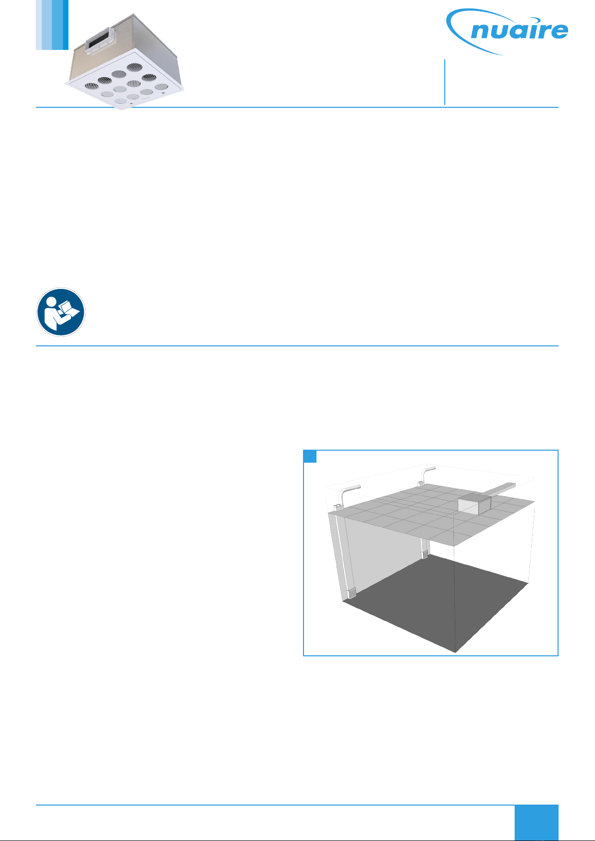
The transition piece should be secured to a suitably rigid structure in
the ceiling void.
The gap between the vertical duct and ceiling cut-out should be fully
sealed with a proprietary low modulus, neutral cure mastic.
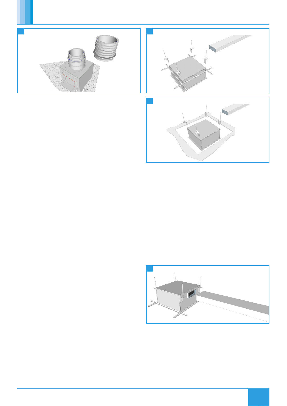
The transition piece is supplied with blanking plates. To remove these,
pull out and retain the wire fixing clip and remove plate from the port.
Ensure that unused ports have blanking plates with sealing rings fitted
and wire fixing clip in place.
The semi-rigid ducting is installed by first locating the sealing ring
provided into the second complete groove in the duct outer surface.
Mark the semi-rigid duct at 35mm from the cut end, and push evenly
into the port aperture. When secure, insert the port’s wire fixing clip
to retain the duct. No further sealing of the connection is required or
should be applied.
This duct type is largely self- supporting, and may be readily cut with
a hacksaw and manually formed into swept bends with a minimum
internal radius of approx. 150mm. Compact 90° bend components are
also available from Nuaire with similar sealed port design (product
code NRDD75-90).
For extended lengths of duct, supports with a maximum spacing of 1m
must be provided.
The duct must not be used to support the weight of the transition
housing or other components. If the duct becomes kinked or crushed,
the affected section must be discarded and replaced.
Once the installation is complete, the facia plate may be attached to
the lower surface of the housing to obscure the cut edges of the ceiling
hole using screw caps provided and screws / plugs appropriate to the
ceiling type.
If required, the facia plate may be carefully trimmed to shape with
metal shears.
4.0 MAINTENANCE
It is important that maintenance checks are recorded and that the
schedule is always adhered to, in all cases, the previous report should
be referred to.
Note and ensure that the position of adjustable louvres is
maintained during the maintenance operation.
4.1 HTS1, HTE1, HTE2 & HTE3 Maintenance
The single supply terminal (HTS1) and extract terminals (HTE1/2/3)
require cleaning only when necessary – vacuum and wipe over with a
clean damp cloth – do not use cleaning agents on these products.
Check for damage and visible obstructions to louvre / grille and rectify /
remove as necessary.
4.2 HTS4, HTS9 & HTS12 Maintenance
As required, clean the visible surface of the terminal - vacuum and wipe
over with a clean damp cloth – do not use cleaning agents on these
products.
Check for damage and visible obstructions to louvres and rectify /
remove as necessary.
4.3 Filter Maintenance
Where a filter has been fitted to a Haven terminal, it will have been
selected for its particular properties and must only be replaced
with a new filter with the same properties.
Failure to observe this requirement will result in compromising the
intended level of Indoor air quality in the occupied space, and may
be detrimental to the health and well-being of occupants.
Filter changing should be carried out in accordance with the system
design requirements, but an annual filter change is the minimum
requirement. Failure to do so may impair the performance and
energy efficiency of this unit.
The filter is accessed through the hinged lower panel of the terminal.
The panel is hinged at the side opposite to the retaining latches.
Undoing the latches will free the panel and a weight of up to 4kg will be
released.
Whilst manually supporting the panel centrally between the latches,
release them in turn by rotating through 90°.
Gently lower the hinged panel down to its greatest extent.
The filters are 525 x 460 x 80mm and weigh up to 4kg (ePM1 type) and
5kg (E11 type).
Remove the old filter, place in a suitable bag and seal.
Remove the new filter from its packaging and refit in housing.
Lift the hinged panel to its original position and re-secure the latches
(full 90 degree rotation).
16 Filter Replacement 1

6
08. 04. 21. Document Number 671971
Nuaire | Western Industrial Estate | Caerphilly | CF83 1NA | nuaire.co.uk
HTS / HTEInstallation Manual
17 Filter Replacement 2
4.4 Replacement Supply Filter Codes
Filter Grade Replacement Supply Filter Code
ePM1>55% HTS-PM1.55-FILTER
ePM1>80% HTS-PM1.80-FILTER
E11 (HEPA) HTS-E11-FILTER
5.0 WARRANTY
The 2 year warranty starts from the day of delivery and includes parts
and labour for the first year. The remaining period covers replacement
parts only (replacement filters not included).
This warranty is void if the equipment is modified without
authorisation, is incorrectly applied, misused, disassembled, or not
installed, commissioned and maintained in accordance with the details
contained in this manual and general good practice.
The product warranty applies to the UK mainland and in accordance
with Clause 14 of our Conditions of Sale. Customers purchasing from
outside of the UK should contact Nuaire International Sales office for
further details.
Failure to maintain the unit as recommended will invalidate the
warranty.
6.0 END-OF-LIFE AND RECYCLING
Where possible Nuaire use components which can be largely recycled
when the product reaches its end-of-life:
•Sheet metal parts, aluminium extrusion, heating/cooling coils and
other metallic items can be segregated and fully recycled.
•EPP, plastic ducting, nylon corner pieces, plastic heat exchangers,
packaging material and other plastic components can be
segregated into mixed plastic and widely recycled.
•Cardboard packaging, wood, used filters and other paper
components can be largely recycled or fully processed in energy
from waste centres.
•Remaining Items can be further segregated and processed in
accordance with the zero waste hierarchy. Please call After Sales
Support for further information on items not listed above.
Ensure that Nuaire product is made safe from any electrical / water
/ refrigerant supplies before dismantling commences. This work
should only be undertaken by a qualified person in accordance with
local authority regulations and guidelines, taking into account all
site based risks.
7.0 AFTER SALES AND REPLACEMENT PARTS
For technical assistance or further product information, including spare
parts and replacement components, please contact the After Sales
Department.
If ordering spares please quote the serial number of the unit together
with the part number, if the part number is not known please give a full
description of the part required. The serial number will be found on the
identification plate attached to the unit casing.
Telephone 02920 858 400
aftersales@nuaire.co.uk
Technical or commercial considerations may, from time to time,
make it necessary to alter the design, performance and dimensions
of equipment and the right is reserved to make such changes without
prior notice.

7
08. 04. 21. Document Number 671971
Nuaire | Western Industrial Estate | Caerphilly | CF83 1NA | nuaire.co.uk
HTS / HTEInstallation Manual
NOTES

8
08. 04. 21. Document Number 671971
Nuaire | Western Industrial Estate | Caerphilly | CF83 1NA | nuaire.co.uk
HTS / HTEInstallation Manual
NOTES
This manual suits for next models
1
Table of contents