Nuprodx multichair 6000Tilt User manual

ASSEMBLY INSTRUCTIONS FOR THE MULTICHAIR 6000Tilt Series
!ATTENTION: READ BEFORE ASSEMBLING/OPERATING!
multichair 6000Tilt multichair 6200Tilt
multichair 6000Tilt P2multichair 6000Tilt P1
November 2012

A The multiCHAIR 6000Tilt, 6200Tilt, 6000Tilt P1, and 6000Tilt
P2 are composed of three sections: the roll-in section with (2)
straight legs & 5” casters, (2) bent legs & 5” casters, the connec-
tor bridge section, and the tub section which has non-pinned
offset legs and adjusting feet. The chair is shipped standard with
the tub section positioned on the user’s left side.Unpack all parts
from the shipping carton.
BRemove all tape and/or packing from the chair. Keep shipping
materials for future use. Note the location of padding materials
and sheet-plastic which protects parts of your chair.
CPosition the frames upside down and install the legs (Refer to
Figure 1)
DPosition the roll-in section rear bent legs so that they points
out at a 90-degree angle. Make sure that the legs slide “home”
into the socket of the seat frame. Use the included yellow T-han-
dle Allen wrench to securely tighten the bolts located at the cor-
ners of the frame.
E The tub section legs do not have an indexing pin and can be
rotated to best fit into the bath tub or shower stall. . Leg height
adjustment is performed by pressing in the brass button on each
leg. Fine tune height adjustment is performed by rotating the
threaded feet at the bottom of the legs. There is a jam nut on
each threaded leg bottom that can be tightened in place with a
small Crescent wrench. The side suction cup assemblies are to
secure the unit inside the tub. The suction faces of the cups
should be parallel with the side tub walls. Then extended them
out to create a tight fit within the tub. The yellow T-handle wrench
is needed to make the adjustments.
FTurn the chair right side up and install the backrest assembly.
Slide the two backposts into the back of the seat frame and tight-
en the two socket head cap screws using yellow T-handle Allen
wrench (Refer to Figure 2).
G The footrests drop into the footrest brackets
!ATTENTION: PLEASE READ!
Figure 1
ASSEMBLY INSTRUCTIONS
Please see LIMITED WARRANTY of these instructions. If the warranty is not acceptable, contact Nuprodx, Inc. for information about
returning the chair for a refund (Restocking fees and shipping charges will be applied). This chair is designed and intended for indoor
shower and bathroom use. It is not designed for outdoor use and will void the warranty if used in this fashion. If thresholds, shower
curbs or barriers are encountered that exceed ½” in height, the area in question should be brought within the code for disabled acces-
sibility.
NOTE!
If you need to position the chair so the tub is on the user’s right
side, refer to the Additional Assembly Instructions on Page 3.
Figure 2
SAFETY PRECAUTION!
If any of the legs are not fitted correctly into the socket of the seat
frame or are not securely tightened there is an extreme risk of the
legs dislodging completely from the chair. This could cause seri-
ous injury or even death!
- PAGE 1 -

H The calf support assembly is simply slide into the mounting
block (Refer to figure 3), and be adjusted by sliding it within the
mounting block than then pushing it down to engage one of the
bottom slots on the square tube.
I Place the connector bridge into the matching holes on both
the roll-in section and tub section (Refer to Figure 3).
SAFETY PRECAUTION!
Both backrest posts must be completely engaged with the seat
frame and securely tightened. If they are not fitted correctly, there
is a risk of the posts dislodging from the seat frame.
This could cause serious injury or even death!
SAFETY PRECAUTION!
The swing-away footrests should be installed into the footrest
clamps after the user has been transferred into the chair. Putting
an extreme amount of weight on the swing-away footrests or
using them as an assistive device when transferring can cause
the entire chair to tip forward, resulting in serious injury or even
death!
SAFETY PRECAUTION!
The connector bridge must be fully seated into the corresponding
holes of both the roll-in section and tub section. If this is not done
correctly, the seat frame could dislodge itself from the chair when
transferring from the roll-in section to the tub section.
- PAGE 2 -
Figure 5
JThe shuttle frame is released from the roll-in base by pulling
back on the underside release lever and simultaneously sliding
the shuttle towards the tub section base (Refer to Figure 4).
KThe tilt mechanism is operated by pulling the spring loaded
crank lever outwards and rotating the handle. Once the tilt angle
is reached, we recommend either having the unit at its
highest/largest tilt angle or flat, slowly release the spring loaded
lever and it will automatically lock itself its pin into one of the
indexing holes on the indexing disk (Refer to Figure 4)
L Index the handle by first positioning the seat in the horizontal
position. The end of the crank handle should be approximately
over the flat head socket bolt on the frame.
Figure 3
Figure 4
H
I
J
K
L

Figure 8
Reconfigure the multiCHAIR 6000Tilt, 6200Tilt,
6000Tilt P1, and 6000Tilt P2 with the Tub Section on
the user’s left side (Refer to Figures 6 and 7) The roll-
in section and tub section frames are identical. To change
slide direction do the following:
A Unbolt the sheet metal calf support plate using a large
Phillip head screw driver and a small Crescent wrench and
then reinstall it on the other frame.
BMove the latch stops as shown using the 5/32” Allen
wrench that is provided with the slider
CMove the complete leg assemblies and the side suction
cups from one frame to the other.
D Relocated the tilt system crank handle from one side of
the shuttle frame to the other side
E Adjustments to the “Tilt Assembly” (Refer to Figure 5 on
page 2 and Figure 7 this page) need to be made as fol-
lows: Remove the “crank handle” by removing the socket
screw with an 1/8” Allen wrench. Remove the cap from the
opposite side of the frame, again using an 1/8” Allen
wrench, and install it on this side. Reinstall the crank han-
dle on the opposite side of the frame. NOTE: position the
seat in the horizontal position and the crank handle should
be approximately covering the flat head socket bolt on the
frame.
F Move the slider latch to the opposite side of the tilt
assembly:
1) Remove the 1/4-20 Flat Head Socket Screw with the
5/32 Allen wrench that is provided with the slider.
2) The second 1/4-20 Flat Head Socket Screw is bolted to
a nylon insert lock nut. Therefore a small crescent wrench
or a 7/16” open end can be used to hold the nut while turn-
ing the screw.
3) Position the latch on the opposite side of the frame and
reinstall.
Cantilever Arms: If desired, the cantilever arms can be
removed from the backrest assembly for storage during
traveling. This can be accomplished by unscrewing the
socket head cap screws that attach the arms to the back-
rest posts using the 5/32” Allen wrench. Then remove the
arm assemblies from the posts and re-insert the socke
head cap screws into the arm assemblies, so they are not
lost. To re-install the cantilever arms, simply follow the
steps above in reverse (Refer to Figure 8).
ADDITIONAL ASSEMBLY INSTRUCTIONS
Figure 7
Release Latch Assembly: Do not attempt to unscrew the inner
slotted screws. Doing so can cause the entire latch assembly to
come apart, rendering it useless (There is no tool provided for this
operation) .
- PAGE 3 -
NOTE!
Figure 6
A
B
D
C
E
F

Inner Leg
Adjustment
Crutch Tip
Adjustment
AEnsure all fasteners (bolts/washers) are securely tightened
and all chair parts have been assembled correctly (Refer back
to Assembly Instructions if needed. Contact Nuprodx, Inc. if
unsure of anything).
BPlace the assembled tub section of the slider into the desired
position of the bath tub (Refer to Figure 13).
CPosition the assembled roll-in section of the slider next to the
outside wall of the bath tub (Refer to Figure 14).
DAdjust the height of the tub section to match the height of the
roll-in section by either adjusting the four inner legs (tub sec-
tion) and/or the adjustable crutch tips (tub section) - Refer to
Figure 15.
EInsert the connector bridge into the four eyelet holes (Two
located on the roll-in section and two located on the tub sec-
tion) - Refer to Figure 16. Switch the four shoulder screws to
the lock position on the connector bridge (Refer to Figure 17).
FRelease the latch mechanism on the roll-in section and slide
the slider seat assembly onto the tub section, making sure the
latch engages fully and locks in place. If the roll-in section and
tub section are not level in height or out of alignment, the slider
seat assembly will not function correctly and safely. To ensure
the safety of the user, make adjustments to both sections as
needed and retry Step F (Refer to Figure 18).
GRemove the connector bridge to test the stability of the tub
section. Also, ensure that the slider seat frame is locked into
place and will not remove during use. Once this is complete,
replace the connector bridge and slide the slider seat frame
back to the roll-in section. The connector bridge can then be
removed and the chair is ready for use.
OPERATING INSTRUCTIONS
Figure 13
Figure 15
Figure 16
Figure 14
Figure 17
- PAGE 4 -
Figure 18

D Cantilever Arms: The cantilever arms can be adjusted to the
desired height by completing the following steps: Loosen the
socket head cap screws on the arm clamps, raise/lower the
arms accordingly, then re-tighten the socket head cap screws
(Refer to Figure 19). For safety purposes, the cantilever arms
lock in the down position. To switch the arms to the up position,
simply push the arms toward the back of the chair (releasing
the locking mechanism) and lift up (Refer to Figure 20).
E Footrest Assemblies: Footrest clamps are installed on the
front legs at the factory. Slide the footrest into the clamp.
Loosen the pinch bolt on the footrest clamp and slide up/down
as required by the user’s leg length (Refer to Figure 21).
Figure 19
Figure 20 Figure 21
- PAGE 5 -

Release Latch
A Leg Height Adjustment: When making height adjustments to
any of the legs, make sure that the brass buttons are fully
engaged into the outer legs. If pushed too hard the button
could become stuck inside the inner leg (Contact Nuprodx, Inc.
if this occurs). Leg height adjustment should only be made
before transferring the user into the chair (Refer to Figure 22).
BCaster Wheels: When transferring into the chair, out of the
chair and sliding the user from the roll-in section into the tub
section, all four caster wheels should be securely locked in
place. Failure to do so could cause the chair to become unsta-
ble (Refer to Figure 23).
CFasteners: Over time the screws and washers on the chair
may become loose. It is very important that these are checked
and securely tightened before each use. Failure to do so could
cause a part to dislodge from the chair (Refer to Figure 24).
DRelease Latch: Verify that the release latch is fully engaged
on the slider seat before removing the connector bridge (Refer
to Figure 25).
ELeveling: The roll-in and tub sections must both be level and
equal in height. To further adjust the height on the tub section
legs, rotate the crutch tip feet clockwise or counterclockwise
(Refer to Figure 26).
ADDITIONAL SAFETY PRECAUTIONS
!ATTENTION: PLEASE READ!
WARNING! Failure to account for the afformentioned and the following safety precautions can result in serious
injury to the user or even death!
Figure 23
Figure 22
Figure 24
Figure 25
- PAGE 6 -
Figure 26

A WARRANTY ACTIVATION Please read this warranty before operating or using your multiCHAIR. To activate the
warranty on your multiCHAIR register it online or by phone. By operating or using the chair, you agree to the terms of
this warranty.
B WARRANTY: Nuprodx, Inc. warrants this product against defects in material and workmanship as follows: There is
a 10-Day conditional money-back warranty. During this time period, the customer is permitted to try out the
multiCHAIR, fully-clothed, keeping the chair in “like new” condition (NOTE: “Like new” condition, in terms of the
multiCHAIR, is defined by Nuprodx, Inc. as no visible wear/usage/water marks for the multiCHAIR to be accepted and
refunds issued when returned to Nuprodx, Inc.). If the customer decides that the multiCHAIR will not work for them,
before the 10-Day period has passed and with the authorization of Nuprodx, the chair can be returned for a full refund
minus a 10% restocking charge (NOTE: The customer is responsible for both in-bound and out-bound freight). After
the initial 10-Day period has passed, there is a two-year limited warranty for all parts of the chair, with the exception of
the seat and back cushions (NOTE: Because of the fragile nature of the foam, there is no warranty for the cushions).
The warranty does not cover normal “wear and tear” from everday use of the product and custom parts/custom cushions
are also excluded from the warranty and cannot be returned for a refund under any circumstances. Please see section E
WARRANTY LIMITATION AND EXCLUSIONS for more info on warranty exclusions.
C The warranty period begins on the date you receive the chair. For warranty service, please contact Nuprodx, Inc. no
later than one month following the applicable warranty term. The chair will be repaired or replaced at the discretion of
Nuprodx, Inc. with no charges to you for parts and labor, provided you have proof of purchase and of purchase date.
D DISCLAIMER: Except for the above warranty, and the acknowledgement by Nuprodx, Inc. that the chair, as manu-
factured by it, is fit for the general purpose for which most persons acquire a chair of its kind, Nuprodx, Inc. provides
that you accept the chair as is, without warranties, either express or implied. Nuprodx, Inc. makes no warranty of fit-
ness for your particular purpose and no warranty of merchantability beyond that already stated. No warranties extend
beyond the duration of the express warranty stated above.
E WARRANTY LIMITATIONS AND EXCLUSIONS: The only obligation of Nuprodx, Inc. is to provide the purchaser
with free repair and replacement as described above. This exclusive warranty remedy will not have failed as long as
Nuprodx, Inc. is willing and able to repair or replace as described, but if this remedy should be held to have failed, the
only remaining warranty obligation of Nuprodx, Inc.
shall be to refund the acts beyond the control of Nuprodx, Inc. The
warranty does not cover normal “wear and tear” from everday use of the product. Standard seat/back cushions/custom
parts/custom cushions are not covered under the warranty.
F This warranty gives you specific legal rights, and you may have other rights that may vary from state to state.
G This warranty does not apply to problems arising from normal wear, improper operation, improper maintenance,
improper storage or similar disclaimer of implied warranties, and some do not allow limitations on how long an implied
warranty may last. Some do not allow exclusion or limitation of incidental or consequential damages. So the above
limitations or exclusions may not apply to you.
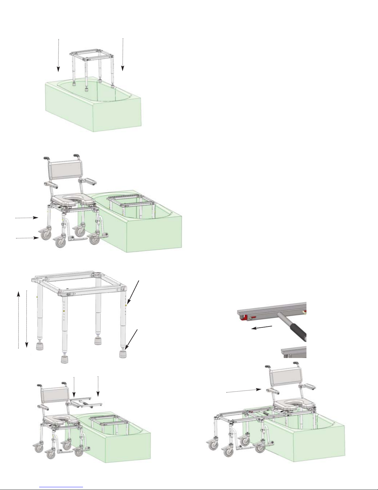
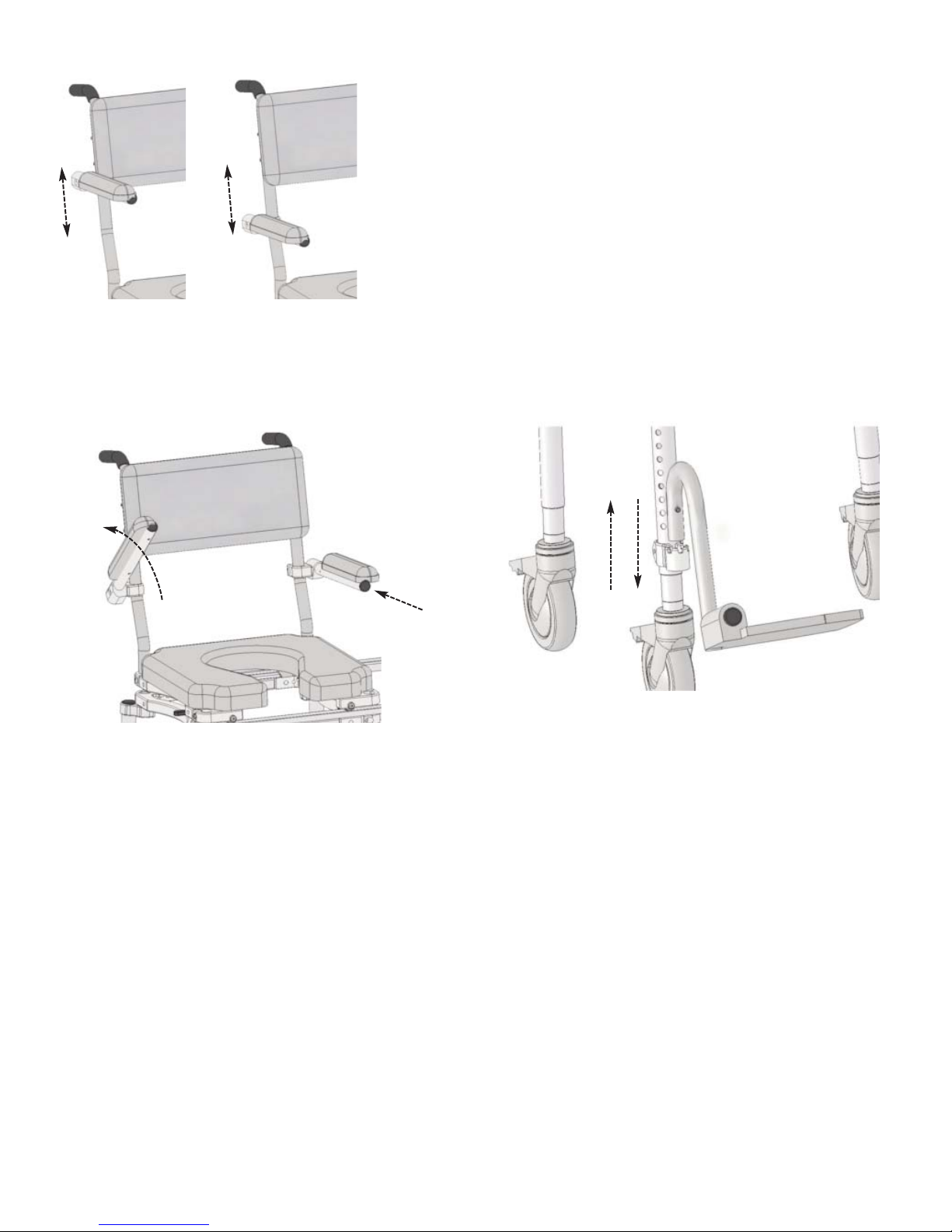
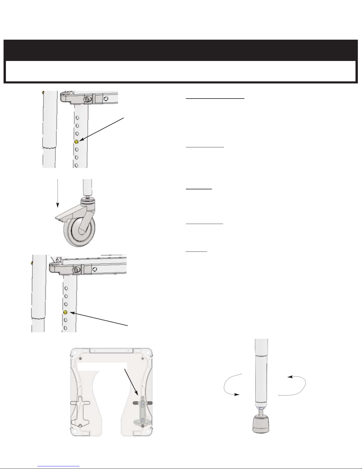
H RETURN INSTRUCTIONS In the event that you need to return the Nuprodx multiCHAIR, please follow the instruc-
tions below:
1) Review the information contained in your warranty to see if this applies to you
2) Obtain a Return Authorization # from Nuprodx, Inc.
3) Re-package the entire chair and its contents in the original packaging and ship to the following address:
LIMITED WARRANTY
- PAGE 7 -
This manual suits for next models
3
Table of contents
Other Nuprodx Wheelchair manuals