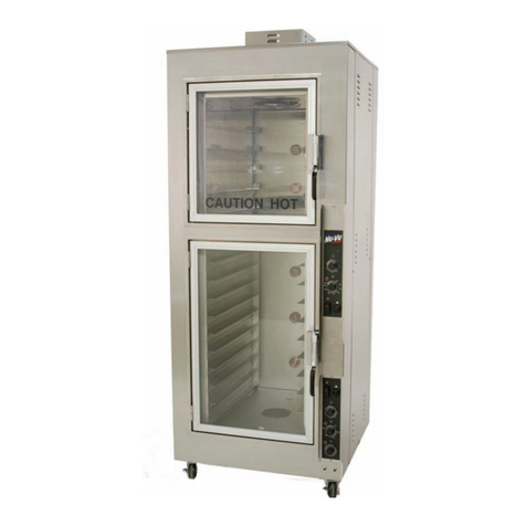
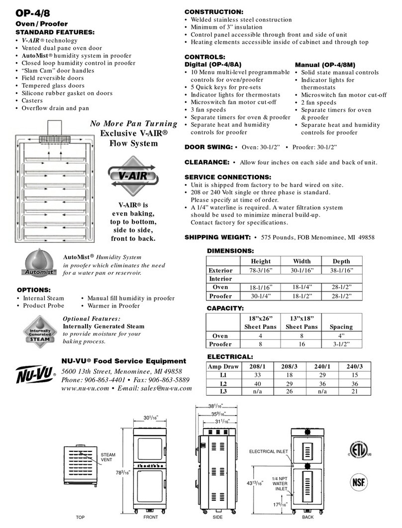
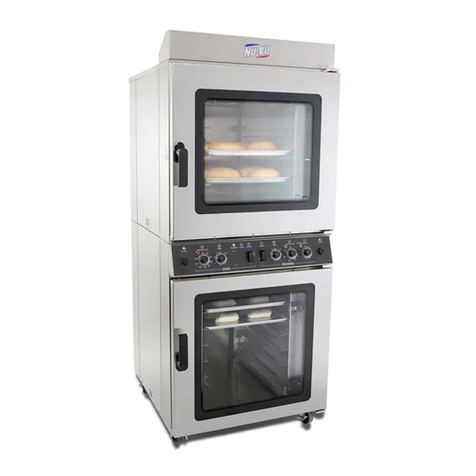
NUVU UB-12R User manual

MENOMINEE, MICHIGAN 49858
(906) 863
-
4401 • (800) 338
-
9886
NU·
VU ®FOOD SERVICE SYSTEMS
For NU–VU® Model:
Roll-In Electric Oven
Revised: 27 July 2006
This page was created using BCL ALLPDF Converter trial software.
To purchase, go to http://store.bcltechnologies.com/productcart/pc/instPrd.asp?idproduct=1
NU–VU® FOOD SERVICE SYSTEMS MENOMINEE, MICHIGAN 49858
(906) 863
-
4401
SALES FAX (906) 863
-
5889 • SERVICE FAX (906) 863
-
6322
(800) 338
-
9886
UB–12R
TABLE OF CONTENTS
ABOUT YOUR NU–VU® EQUIPMENT................... 1
NU–VU® EQUIPMENT WARRANTY...................... 2
RECEIPT AND INSTALLATION.............................. 5
OPERATING INSTRUCTIONS................................ 11
MAINTENANCE AND CLEANING........................... 21
TROUBLE–SHOOTING GUIDE .............................. 22
REPLACEMENT PARTS LIST ................................ 26
This page was created using BCL ALLPDF Converter trial software.
To purchase, go to http://store.bcltechnologies.com/productcart/pc/instPrd.asp?idproduct=1
UB–12R OWNER'S MANUAL
NU–VU® FOOD SERVICE SYSTEMS MENOMINEE, MICHIGAN 49858
(800) 338-9886 SALES FAX (906) 863-5889 • SERVICE FAX (906) 863-6322 page 1
ABOUT YOUR NU–VU® EQUIPMENT
The NU–VU® UB–12R is an electrically powered roll-in Oven. It is constructed entirely of
stainless steel, including the Door and all interior and exterior parts. The Oven is designed to rest on
a non-combustible heat resistant floor surface, allowing the 12-pan stainless steel rack to be rolled
in and out to load and unload the Oven. The Oven and Door are completely insulated with high-
density fiberglass, and the Door is fitted with a high-temperature silicone rubber gasket and sweep
to maintain a high working efficiency.
The UB–12R is manufactured with NU–VU®'s patented V-Air system. This air system is designed
to produce even air flow above and below each individual pan in the Rack by passing heated air
through specially perforated Sidewalls, between the pans, and up the front and back of the Oven to
the air intake in the Oven ceiling. The air is then forced down the air channels, over the Heating
Elements, and back up through the Sidewalls and over your product. The result is a product baked
or cooked evenly top to bottom and side to side, without the need to turn pans. The UB–12R comes
with a standard 550F Temperature Control and a 60 Minute Timer/Buzzer. The four Heating
Elements are each rated at 5200 watts for either 208 volts or 240 volts.
The end-loading Oven Rack is constructed entirely of stainless steel, with a capacity of twelve (12)
full sized 18" x 26" sheet pans or twenty-four (24) 12" x 20" x 2½" food service pans.
Your UB–12R is available with several options:
* INTERNAL STEAM - This system injects a water mist into the heated baking chamber
where it is flashed into steam. This added steam will provide crusty breads or rolls for product
variation.
* EXTERNAL STEAM - An external attached Steam Generator will provide generous
amounts of high-temperature steam to cook vegetables, meats, fish, poultry, seafood or any
other item that can be steamed.
* COOK–N–HOLD - The COOK–N–HOLD system utilizes dual Oven Temperature
Controls and a 24 Hour Timer to bake or cook your product at one temperature and then
automatically shift to a lower holding temperature.
* REVERSING MOTOR - This option includes a reversible Oven Motor and a Reversing
Switch to provide two different air speeds for your baking and cooking needs.
* RETHERMALIZATION - The RETHERMALIZATION package adds increased wattage
to your Oven, allowing the rapid reheating of previously prepared products. This is most often
used by operations running high product volume in a short time frame.
* PRISON PACKAGE - Developed at NU–VU® for use by the California Department of
Corrections, this option features lockable transparent covers over all Oven controls, security
screws on all external parts, an inside Alarm, and an inside-release Door Latch.
* INTERIOR ALARM - Most often used in conjunction with the Prison Package, this bell
Alarm is activated by an internal button in the event that someone is accidentally locked in the
Oven. The button also deactivates the Oven Motor and Heating Elements.
* MINI–CHEF PROGRAMMABLE CONTROL - This simple Programmable Control
supports two modes of operation. Cook allows you to set preheat and cooking temperatures
along with a set cooking time. Cook With Steam is identical to the Cook mode with the
addition of a steam injection time of up to 60 seconds at the beginning of the cooking cycle.
This page was created using BCL ALLPDF Converter trial software.
To purchase, go to http://store.bcltechnologies.com/productcart/pc/instPrd.asp?idproduct=1
UB–12R OWNER'S MANUAL
NU–VU® FOOD SERVICE SYSTEMS MENOMINEE, MICHIGAN 49858
page 2SALES FAX (906) 863-5889 • SERVICE FAX (906) 863-6322 (800) 338-9886
NU–VU® EQUIPMENT WARRANTY
NU–VU® products are warranted against defects in workmanship and materials. No other express
warranty, written or oral, applies. No person is authorized to give any other warranty or assume any
other liability on behalf of NU–VU®, except by written statement from an officer of NU–VU®.
Your NU–VU® equipment warranty will begin as soon as your Warranty Registration Card
(attached to the power block or power cord) is received by our Service Department, and is limited to
the following time periods for the original owner only:
PARTS LABOR
Inside the United States 12 Months 12 Months
All areas outside the United States 12 Months 12 Months
These time limits will apply in all cases unless prior arrangements have been made and agreed to in
writing.
The NU–VU® equipment warranty is composed of the following:
PARTS - -
This warranty covers electro-mechanical, mechanical and electronic components including hinges,
latches, thermostats, sensors, thermocouples, heating elements, relays, contactors, solenoids, power
terminal blocks, timers, buzzers, micro switches, motors, motor speed controls, rocker switches,
valves, doors, blower wheels, water pans, and similar components. Defective parts or components
are warranted for the appropriate time period described above. Replacement parts and components
covered by this warranty will ship C.O.D.; customers who maintain an open account may purchase
against their account. The return of defective parts is required. The return of a defective part or
component must be made prior to the issuance of a credit on an open account. If a part that is
returned tests satisfactory in the NU–VU® factory or at an authorized NU–VU® dealer or service
agency, NU–VU® may withhold issuing credit. Replacement parts will be warranted for a period of
ninety (90) days provided they are installed in a manner authorized by NU–VU®.
The following are excluded from the parts warranty:
• Parts damaged by freight or handling beyond the confines of the NU–VU® factory
• Electrical components (including heating elements) damaged due to improper installation,
or incorrect power supply or wiring
• Any part or component deemed defective because of misuse, abuse or failure to follow
procedures listed in the Owner's Manual
• Light bulbs, bulb sockets, fuses and gaskets
• Steam generator elements which fail due to accumulated mineral deposits
• Leaks resulting from the removal of sealant in the Oven
LABOR - -
We require that you call our NU–VU® Service Department at (800) 338-9886 for service
authorization BEFORE you call any service agency if you wish to claim a labor expense under the
warranty. We may be able to solve your problem over the telephone, or be able to recommend one
or more capable and reliable service agencies in your area.
This page was created using BCL ALLPDF Converter trial software.
To purchase, go to http://store.bcltechnologies.com/productcart/pc/instPrd.asp?idproduct=1
UB–12R OWNER'S MANUAL
NU–VU® FOOD SERVICE SYSTEMS MENOMINEE, MICHIGAN 49858
(800) 338-9886 SALES FAX (906) 863-5889 • SERVICE FAX (906) 863-6322 page 3
This warranty covers the replacement and installation of those parts and components included under
PARTS for the appropriate time period indicated on the previous page. This coverage is limited to
the normal mileage allowance for a maximum travel radius of up to fifty (50) miles, and the normal
labor rate times the allowable hours for performing the work as set forth in the following listing:
NU–VU® FOOD SERVICE SYSTEMS
STANDARD TIME ALLOWANCES FOR WARRANTY REPLACEMENTS
CHANGE PERFORMED CHANGE TIME TEST TIME TOTAL TIME
Oven Motor, Rebalance Fan 1 hr. ½ hr. 1½ hr.
Oven Heating Element 1 hr. ½ hr. 1½ hr.
Control Circuit Board ½ hr. ½ hr. 1 hr.
Control Sensor ½ hr. ½ hr. 1 hr.
Timer and/or Buzzer ½ hr. 5 min. ½ hr.
Contactor/Relay ½ hr. 5 min. ½ hr.
Power Switch ¼ hr. 5 min. ¼ hr.
Indicator Light ¼ hr. 5 min. ¼ hr.
These times are based on servicing a unit that has been installed with allowance made for access
panels on the unit. If the unit is built into a wall that makes servicing very difficult or impossible
without removing part of the counter, wall, trim, etc., the extra time for gaining access shall be
charged to the owner of the unit.
NU–VU® has determined that the listed times, which are based on the period of time necessary for
a trained service person to perform the work noted, are fair and reasonable. If a problem is not
diagnosed within a half hour, the service person must contact NU–VU®'s Service Department via
telephone. The Service Department is available for assistance Monday through Friday from 7:00
a.m. to 5:30 p.m. (Central Standard Time). Additional time for problem solving will not be allowed
unless this procedure is followed. An appointment for servicing a unit should be set up since time
will not be allowed for waiting to service a unit. Unless the service person justifies extra time for
performing the work noted, charges for work performed by the service person in excess of the
allowed time shall either be billed to the owner of the equipment or denied.
EXTENDED WARRANTY:
Available at an additional charge. Please ask for a quote depending upon the type of warranty
requested.
IMPORTANT: NU–VU® WILL NOT PAY FOR ANY SERVICE CALLS AS
WARRANTY WORK IF A NU–VU® AUTHORIZED SERVICE AGENCY
DETERMINES THAT YOUR UNIT IS SET UP AND OPERATING
PROPERLY!
This page was created using BCL ALLPDF Converter trial software.
To purchase, go to http://store.bcltechnologies.com/productcart/pc/instPrd.asp?idproduct=1
UB–12R OWNER'S MANUAL
NU–VU® FOOD SERVICE SYSTEMS MENOMINEE, MICHIGAN 49858
page 4SALES FAX (906) 863-5889 • SERVICE FAX (906) 863-6322 (800) 338-9886
WARRANTY LIMITATIONS:
NU–VU®'s warranty for parts and labor is subject to the following limitations:
• NU–VU® will pay for service under warranty if there is a defective component, but not
for:
A service call when the returned part test shows that the part works as per
specification.
Parts or equipment that have been abused, and require replacement or adjustment.
Calls where the problem involves procedures rather than parts or components.
Any overtime charges. NU–VU® will pay straight time only for any work performed
on NU–VU® equipment.
• This warranty will not apply if the unit is moved from the initial place of installation,
unless NU–VU® agrees in writing to continue the warranty after a relocation.
Food service equipment and parts must be installed and maintained in accordance with NU–VU®
instructions. Users are responsible for the suitability of the units or parts to their application. There
is no warranty against damage resulting from accident, abuse, alteration, misapplication, inadequate
storage prior to installation, or improper specification or other operating conditions beyond our
control. Claims against carrier's damage in transit must be filed by the buyer and, therefore, the
buyer must inspect the product immediately upon receipt.
THIS WARRANTY DOES NOT COVER ADJUSTMENTS
DUE TO NORMAL ON-GOING USE!
PARTS RETURN PROCEDURES AND CONDITIONS:
The following procedure shall be followed for the return of parts to the factory for credit
consideration:
• All parts received by NU–VU® must have a completed Return Authorization Form as
supplied by NU–VU® with the part. Complete and return this Authorization Form with
the defective part(s).
• Parts MUST be packed securely so that in-transit damage cannot occur.
• Prepay shipment. Any parts returned collect will be refused by our Receiving
Department. Credit will be issued on proper returns only.
• As soon as parts are tested and confirmed as defective, credit will be issued against them.
• If the engineering test shows the component is not defective and in good working
condition, it may be returned to you along with your request for payment.
This page was created using BCL ALLPDF Converter trial software.
To purchase, go to http://store.bcltechnologies.com/productcart/pc/instPrd.asp?idproduct=1
UB–12R OWNER'S MANUAL
NU–VU® FOOD SERVICE SYSTEMS MENOMINEE, MICHIGAN 49858
(800) 338-9886 SALES FAX (906) 863-5889 • SERVICE FAX (906) 863-6322 page 5
RECEIPT AND INSTALLATION
RECEIPT:
It is essential to inspect the unit immediately when it arrives. NU–VU® has placed instructions on
the packaging to avoid damage in transit. However, an accident or negligent handling of the
packaged unit can produce hidden damage. Please follow these steps after receiving your NU–VU®
unit:
A. Inspect the entire perimeter of the package for damage or punctures to the packing
material. This may indicate damage to the unit inside. Call any and all packing damage to
the attention of the delivery person.
B. If any packing damage is found uncrate the unit immediately in the presence of the
delivery person to determine if the unit is damaged. If any damage is found indicate the
type and amount of damage on the shipping documents and notify NU–VU® at (800)
338–9886 immediately after filing a freight claim.
C. Uncrate the unit carefully and check the entire unit (top, front, back and both sides) for
any visible or hidden damage.
D. Remove the unit from the shipping pallet and inspect the bottom for any damage.
E. If any damage is noted after the driver leaves immediately contact the freight company
and NU–VU® Food Service Systems.
F. Check the Oven Door. Make sure the Door operates freely, closes completely and that the
Door Gasket seals firmly. If the Door does not close and seal properly please contact NU–
VU®'s Service Department for instructions and assistance in any required adjustments.
INSTALLATION PROCEDURES:
NU–VU® recommends that your UB–12R be installed by a licensed professional to ensure the
proper positioning and connections. Failure to install your UB–12R properly may void your product
warranty.
SITE PREPARATION - -
Locate and clear the installation area. Refer to Illustration #1 on page 6 for the external dimensions
of the UB–12R. Allow a minimum of 6" clearance at the back and on both sides of the electrically
powered UB–12R. Make sure the floor is flat and level. If the floor is not flat and level you may
need to use metal shims (or other non-combustible material) under one or more corners of the unit
during the installation.
The floor in the installation area must be of a non-combustible heat-resistant material. The area
immediately in front of your Oven installation should also be of a non-combustible heat-resistant
material to allow you to roll out the hot Oven Rack after a baking/cooking cycle.
Install as many of the ventilation, electrical, and optional water supply lines as you can before the
unit is positioned. Refer to Illustration #1 for the locations of the UB–12R supply connections.
This page was created using BCL ALLPDF Converter trial software.
To purchase, go to http://store.bcltechnologies.com/productcart/pc/instPrd.asp?idproduct=1

UB–12R OWNER'S MANUAL
NU–VU® FOOD SERVICE SYSTEMS MENOMINEE, MICHIGAN 49858
page 6SALES FAX (906) 863-5889 • SERVICE FAX (906) 863-6322 (800) 338-9886
VENTILATION - -
The UB–12R is equipped with a manual adjustable Vent, located on the top of the Oven and
controlled by the green handle just below the Control Panel on the front of the unit. The installation
of your UB–12R may thus require ventilation of some sort, usually ducted to the exterior of your
building. This ventilation may vary from a simple draft stack and hood arrangement to an entire
powered vent hood depending on your type and volume of product. However, hood and venting
codes vary from state to state and from locality to locality. For this reason NU–VU® cannot give
specific detailed information regarding your individual application. However, we do recommend
that any hood device be installed at a floor-to-bottom-edge height of no less than the overall height
of the unit plus one inch. Your licensed contractor or installer is best qualified to determine your
specific needs.
INSTALLATION - -
A check should be made to determine that the power source to be connected is the same voltage and
phase as indicated on the label on the side of the unit. If the voltage and/or phase is not the same
call NU–VU® for instructions on changing the voltage and/or phase of your power supply or unit.
If the power source is compatible with the Oven you can move the unit into the location where it is
to be operated.
NOTE: If your UB–12R is equipped with an optional External Steam Generator please attach
any required drain plumbing to the Generator Drain at this time. The ¾" NPT Drain fitting is
located on the bottom of the Steam Generator.
Make sure there is sufficient clearance around the outside of the unit for safe and efficient
operation. We recommend a MINIMUM OF 6" CLEARANCE from all combustible and non-
combustible surfaces at the back and on each side of the UB–12R. Because the unit is so large and
heavy, it may be impossible for two or even three people to move it later for any required service or
maintenance. Therefore, we recommend that provisions be made during the installation for
adequate access to the top and sides of the unit should service or maintenance ever become
necessary in the future. This can be accomplished by providing increased clearances or through the
installation of movable counters or tables.
The entire unit must be level and sit firmly on the floor. Use metal shims to raise one or more
corners of the unit until the unit is level and sits firmly in place. Make sure the Door Ramp is
attached and that the outside edge is in full contact with the floor.
NOTE: If you had to shim one or both front corners of the unit the Door Ramp may also
need to be shimmed to ensure full support when rolling the Oven Rack in and out of the
Oven.
With the unit in place and the Door Ramp installed, open and close the Oven Door several times.
The Oven Door should open easily and swing freely, but should not move by itself when left in an
open position. If the Door does move the unit is not installed plumb. Add, subtract, or move bottom
shims as necessary until the open Door stays stationary. THIS IS IMPORTANT FOR OPERATOR
SAFETY!!!
Open the Oven Door and roll the Oven Rack in and out of the Oven several times. The Rack should
ride up the Ramp and slide easily into and out of the Oven. Leave the Rack in the Oven and close
the Oven Door.
This page was created using BCL ALLPDF Converter trial software.
To purchase, go to http://store.bcltechnologies.com/productcart/pc/instPrd.asp?idproduct=1
UB–12R OWNER'S MANUAL
NU–VU® FOOD SERVICE SYSTEMS MENOMINEE, MICHIGAN 49858
(800) 338-9886 SALES FAX (906) 863-5889 • SERVICE FAX (906) 863-6322 page 7
ELECTRICAL CONNECTIONS - -
The NU–VU® UB–12R is available in 208-volt or 240-volt configurations for a three phase power
supply only. The UB–12R can also be constructed for use with special voltage requirements (i.e.
480 volt). With the exception of the Heating Elements in the UB–12R all interior electrical
components operate from one power leg or the other, at 120 volts to neutral.
A check should be made to determine that the power source to be connected is the same voltage and
phase as indicated on the label on the side of the unit. If the voltage and/or phase is not the same
you should call NU–VU® for instructions on changing the voltage and/or phase of your power
supply or unit.
The UB–12R should be connected by a licensed electrician or installer according to all applicable
local, state and national electric codes. All electrical connections must be made with COPPER
WIRE ONLY in the correct gauge for the application. The unit may be connected either with a
plug-type connection or through direct wiring. Allow enough slack in the wiring connection to
allow for equipment to be moved during installation or any required maintenance or servicing.
Your licensed electrician should remove the back half of the Oven's top to expose the power
terminal connections. A wiring schematic for the unit is attached to the wiring near the Power
Terminal Block.
WARNING: DO NOT ATTACH UNIT IF THE POWER SOURCE DOES NOT
COINCIDE WITH THE UNIT LABEL!!!
IMPORTANT: ALL POWER SHOULD BE TURNED OFF AT THE MAIN
BREAKER WHILE THE UNIT IS BEING CONNECTED!!!
Illustration #2
This page was created using BCL ALLPDF Converter trial software.
To purchase, go to http://store.bcltechnologies.com/productcart/pc/instPrd.asp?idproduct=1
UB–12R OWNER'S MANUAL
NU–VU® FOOD SERVICE SYSTEMS MENOMINEE, MICHIGAN 49858
page 8SALES FAX (906) 863-5889 • SERVICE FAX (906) 863-6322 (800) 338-9886
This page was created using BCL ALLPDF Converter trial software.
To purchase, go to http://store.bcltechnologies.com/productcart/pc/instPrd.asp?idproduct=1

UB–12R OWNER'S MANUAL
NU–VU® FOOD SERVICE SYSTEMS MENOMINEE, MICHIGAN 49858
(800) 338-9886 SALES FAX (906) 863-5889 • SERVICE FAX (906) 863-6322 page 9
The following steps should be carefully observed while completing the electrical connections:
A. Take note of the labeling on the unit's terminal connections (Line 1, Line 2, Line 3,
Neutral) at the Power Terminal Block.
B. Carefully identify the power source leads and attach them to the appropriate connection
terminals. Power leads carrying 208 voltage may be attached to any of the Line terminals.
In the case of a 240v three phase power supply the wild leg (240v to neutral) must always
be attached to Line 2 (L-2). Make sure all connections are clean and tight.
C. Be sure the unit is properly grounded before use by attaching a grounding wire to the
Ground Lug next to the Power Terminal Block.
D. Carefully set all Controls and Switches on the unit to the OFF position and engage the
main power supply.
E. Check the voltage at the Power Terminal Block connections with a voltmeter to confirm
conformity with the unit requirements as listed on the side label. Disengage the main
power supply.
F. If all voltage readings are correct you may continue with the installation. If the readings
DO NOT coincide with the unit requirements you must call NU–VU® for instructions on
changing the voltage and/or phase of your power source or equipment.
OPTIONAL WATER SUPPLY CONNECTIONS - -
The water connection required for some of the UB–12R options is located at the back of the unit
near the top (refer to Illustration #1 on page 6). This single ¼" connection will supply all the water
that your Oven option(s) may require.
IMPORTANT: NU–VU® strongly recommends that SOFT WATER ONLY be used in any unit
requiring a water supply. Also, a good quality water filter MUST be installed in-line between the
unit connection and the water supply to guard against clogging and mineral build-up in the
components. This is extremely important in areas having hard water. This water filter may be
installed in-line at the water source or adjacent to the Water Inlet Fitting on the unit, whichever is
more convenient for you.
Please follow these instructions to install any optional water supply:
A. Run approved copper, plastic or vinyl tubing from the water source to the unit's location
and install a shut-off valve. Allow some slack for final unit positioning and service. Avoid
any kinks or strains on the tubing and place the tubing where it will not be damaged in
any way.
B. The tubing end that attaches to the unit must not be damaged or deformed in any way.
The cut end should be cut straight and clean with no deforming of the tubing. All burrs
and sharp edges should be removed to ensure a proper and leak-free connection.
C. Position the tubing so that the tubing runs straight into the Water Intake Fitting. Be
careful not to kink the tubing if you bend it, and do not bend the tubing within two (2)
inches of the end.
IMPORTANT: IN ANY 240–VOLT THREE PHASE SYSTEM THE WILD LEG
(240 VOLTS TO NEUTRAL) MUST ALWAYS BE CONNECTED TO L-2!!!
This page was created using BCL ALLPDF Converter trial software.
To purchase, go to http://store.bcltechnologies.com/productcart/pc/instPrd.asp?idproduct=1
UB–12R OWNER'S MANUAL
NU–VU® FOOD SERVICE SYSTEMS MENOMINEE, MICHIGAN 49858
page 10 SALES FAX (906) 863-5889 • SERVICE FAX (906) 863-6322 (800) 338-9886
D. The two-part compression fitting (tapered collar and nut) is placed approximately 1" onto
the tubing so that the collar is inside of the nut and the threaded opening of the nut is
toward the intake fitting.
E. Push the tubing all the way into the Water Intake Fitting (as far as it will go) and hold it
there while you thread the compression nut onto the Water Intake Fitting. Tighten the
compression nut with an open-end wrench, but do not over–tighten the fitting! If the joint
leaks when tested and further gentle tightening does not stop the leak, the two-part
compression fitting must be replaced.
Careful attention to these simple procedures will help to ensure an installation without leaks. If you
have any questions or problems please call NU–VU®'s Service Department at (800) 338–9886.
This page was created using BCL ALLPDF Converter trial software.
To purchase, go to http://store.bcltechnologies.com/productcart/pc/instPrd.asp?idproduct=1
UB–12R OWNER'S MANUAL
NU–VU® FOOD SERVICE SYSTEMS MENOMINEE, MICHIGAN 49858
(800) 338-9886 SALES FAX (906) 863-5889 • SERVICE FAX (906) 863-6322 page 11
OPERATING PROCEDURES
The standard manual UB–12R Controls are as follows:
POWER SWITCH
The Power Switch/Circuit Breaker allows electrical power to flow from the power source
to the operational components of the Oven. Setting the Power Switch to OFF will stop all
operations and remove all power from the components.
TEMPERATURE CONTROL
The Oven Temperature Control is used to select and regulate the Oven's internal
temperature.
OVEN TIMER
This 60 Minute Timer is used in conjunction with a Buzzer Alarm to provide an audible
warning at the end of a timed cooking, baking or steaming cycle.
VENT CONTROL
The UB–12R is equipped with a single manually-controlled Steam Vent. This Adjustable
Steam Vent is operated by the green Vent Control Handle on the front of the unit just
below the Control Panel. This Vent must be at least partially open at all times, and should
never be closed completely.
Illustration #3 above shows a UB–12R Control Panel with all of the Controls necessary for all of
the options (standard features are shown in solid lines, optional features are indicated with dashed
lines). Your UB–12R will not have all of these Controls, but it will have some of them. The actual
types of Controls installed on your UB–12R will depend on the options you have chosen for your
unit.
Illustration #3
WARNING: COMPLETELY CLOSING THE STEAM VENT DURING ANY
COOKING OR BAKING OPERATION MAY LEAD TO A DANGEROUS
BUILD-UP OF STEAM PRESSURE THAT COULD RESULT IN SERIOUS
PERSONAL INJURY OR EQUIPMENT DAMAGE IF IT WERE SUDDENLY
RELEASED!!!
This page was created using BCL ALLPDF Converter trial software.
To purchase, go to http://store.bcltechnologies.com/productcart/pc/instPrd.asp?idproduct=1
UB–12R OWNER'S MANUAL
NU–VU® FOOD SERVICE SYSTEMS MENOMINEE, MICHIGAN 49858
page 12 SALES FAX (906) 863-5889 • SERVICE FAX (906) 863-6322 (800) 338-9886
The optional manual UB–12R Controls are as follows:
STEAM SWITCH
This Steam Switch controls the INTERNAL STEAM option. Pressing and releasing the
Steam Switch will cause a water mist to be sprayed into the hot Oven for a few seconds,
creating a light steaming of your product.
STEAM TIMER
The Steam Timer is a 60 Minute Timer identical to the standard Oven Timer, but used to
control the EXTERNAL STEAM option. The Timer can be set for however long you
want the EXTERNAL STEAM generator to continue supplying steam to the interior of
the Oven with automatic steam shut-off when the Steam Timer expires.
99-MINUTE DIGITAL TIMER
This Timer provides a digital input/output with a maximum cycle time of 99 minutes. It
does not control any Oven functions, but will provide an audible alarm via an inter-
connected Buzzer at the end of any entered time cycle.
24–HOUR TIMER
The 24 Hour Timer is the first part of the COOK–N–HOLD option. Used in conjunction
with the Hold Control the 24 Hour Timer is set for the desired length of time you wish to
cook or bake. At the end of that time the 24 Hour Timer will automatically switch control
of the Oven temperature to the Hold Control.
HOLD
The Hold Control is the second half of the COOK–N–HOLD option. Set the Hold
Control to whatever temperature you wish to hold your finished product at. When the 24
hour Timer expires control of the Oven temperature is switched to the Hold Control,
allowing a hands-off holding of your product until you are ready to use it.
MOTOR REVERSING SWITCH
Your UB–12R can be equipped with a Motor Reversing Switch. There are three positions
for this Switch:
OFF Turns the Oven Motor OFF. You must set the Motor Reversing Switch to this
position first and allow the Motor to come to a complete stop whenever you
switch the Motor from HI to LO or from LO to HI.
HI Motor rotation is counter-clockwise, air velocity and volume are highest.
LO Motor rotation is clockwise, air velocity and delivery volume are reduced.
NOTE: The Blower Wheel is designed to give a different air velocity when the rotation is
reversed. The HI setting will give the highest velocity and volume of heated air while the
LO setting will deliver less air at a reduced velocity. The Motor Reversing Switch DOES
NOT reverse the direction of the air flow in your Oven, but only changes the velocity. The
HI setting can be used for breads and rolls, while the LO setting can be used for delicate
items such as cakes. The LO setting is also particularly useful for slow-roasting meats
when used in conjunction with the COOK–N–HOLD feature.
INTERIOR ALARM
The interior Alarm is used in conjunction with the Prison Package to prevent someone
from being accidentally locked in the Oven. A small metal button just inside of the
doorway can be pressed to activate a bell Alarm; this button also deactivates the Oven
Motor and Heating Elements. The Alarm can only be deactivated by turning OFF the
Oven power supply at the wall breaker.
PROGRAMMABLE CONTROL
The optional UB–12R Programmable Control is identified and outlined beginning on
page 17.
This page was created using BCL ALLPDF Converter trial software.
To purchase, go to http://store.bcltechnologies.com/productcart/pc/instPrd.asp?idproduct=1
UB–12R OWNER'S MANUAL
NU–VU® FOOD SERVICE SYSTEMS MENOMINEE, MICHIGAN 49858
(800) 338-9886 SALES FAX (906) 863-5889 • SERVICE FAX (906) 863-6322 page 13
Instructions for the correct operation of your NU–VU® UB–12R are detailed on the next few
pages. Procedures are listed for the standard operation as well as for each of the listed options. If
you have any problems or questions concerning the operation of this Oven or any of its options
please call our Service Department for assistance at (800) 338-9886 Monday through Friday
between the hours of 7:00 AM and 5:30 PM (Central Standard Time).
PRE-HEATING:
At the beginning of the work day you may want to pre-heat your Oven approximately 25higher
than the required operating temperature. Since your Oven requires time to reach the proper
operating temperature (approximately 15 minutes to stabilize at 400F) you should plan ahead so
the Oven and your product are ready at the same time. When the desired temperature is reached the
Temperature Control Indicator Light will go out. It is not necessary to reset to pre-heat temperature
with each load unless you are processing new items at a much higher temperature.
To pre-heat the Oven:
A. Remove the Oven Rack, close and latch the Oven Door. Set the Oven Power Switch to the
ON position.
B. Set the Temperature Control to a temperature 25higher than the required processing
temperature for your product. The Temperature Control Indicator Light will illuminate as
the Oven begins to heat up.
C. Allow the Oven to pre-heat (approximately 20 minutes to reach 400F from a cold start).
You may set the Timer as a reminder. The Temperature Control Indicator Light will go
out when the set pre-heat temperature is reached.
STANDARD OPERATIONS:
A. Remove the Oven Rack, close and latch the Oven Door. Set the Oven Power Switch to the
ON position.
B. Determine the correct processing temperature for your selected product and set this
temperature on the Temperature Control (refer to PRE-HEATING). The Temperature
Control Indicator Light will illuminate as the Oven begins to heat.
(IMPORTANT: The Temperature Control Indicator Light will illuminate only when the
Temperature Control calls for heat. The Temperature Control Indicator Light may cycle
ON and OFF as the Oven operates. This is normal, and may happen several times during
an operating cycle.)
C. Prepare your product while the Oven is heating. Place it on baking pans or in food service
pans and load the pans onto the Oven Rack. Make sure the baking or food service pans
are positioned correctly to maximize the benefits of the unique air flow in the Oven. Full-
size and half-size sheet pans as well as the food service pans should be centered between
the raised tabs on the Pan Slides in the Oven Rack.
D. The Temperature Control Indicator Light will go out when the Oven reaches the selected
temperature. Open the Oven Door and roll in the loaded Oven Rack, pushing it all the
way to the rear of the Oven. Make sure you load it into the Oven with the Rack Pan Stop
to the back. Close and latch the Oven Door securely.
E. Reset the Temperature Control (if you have pre-heated your Oven to a higher
temperature) to the correct operating temperature.
F. Set the desired processing time on the 60 Minute Timer. This will provide an audible
reminder at the end of the processing cycle.
This page was created using BCL ALLPDF Converter trial software.
To purchase, go to http://store.bcltechnologies.com/productcart/pc/instPrd.asp?idproduct=1

UB–12R OWNER'S MANUAL
NU–VU® FOOD SERVICE SYSTEMS MENOMINEE, MICHIGAN 49858
page 14 SALES FAX (906) 863-5889 • SERVICE FAX (906) 863-6322 (800) 338-9886
G. Set the Adjustable Steam Vent to the desired position. Light bakery products may require
a Vent that is only slightly open (almost horizontal), while a very wet load of product
(such as potatoes or chicken) will require a Vent that is fully open (in the vertical
position).
H. When the Timer expires the Buzzer Alarm will sound. Set the Timer to OFF to silence
the Alarm. Carefully open the Oven Door and pull out the Oven Rack containing the
finished product. USE CAUTION!! The stainless steel Rack is HOT and will remain HOT
for several minutes.
INTERNAL STEAM OPTION:
This option uses a push-and-release Steam Switch to activate an internal interval timer along with a
Solenoid Valve. This allows a fine water mist to be sprayed into the Oven Blower Wheel where it is
immediately vaporized and circulated throughout the hot Oven.
The INTERNAL STEAM option can be utilized any time in the processing cycle (at the beginning,
in the middle, or at the end).
To operate the INTERNAL STEAM option:
A. Increase the setting of the Oven Temperature Control just enough so that the Temperature
Control Indicator Light comes on.
B. Press and release the spring-loaded Steam Switch to activate the internally-timed water
spray. The Solenoid Valve will open, allowing water to be sprayed into the hot Oven
where it flashes into steam. The water spray will automatically discontinue after a few
seconds. The Steam Switch can be pressed again to repeat the process as many times as
you feel necessary.
C. Reset the Oven Temperature Control back to the original temperature (if necessary).
NEVER OPERATE THE OVEN WITH THE VENT FULLY CLOSED!!!
CAUTION: STAND AWAY FROM THE FRONT OF THE OVEN WHEN
OPENING THE DOOR AFTER ANY COOKING CYCLE TO AVOID
EXPOSURE TO ESCAPING HEAT AND STEAM!!!
IMPORTANT: THE INTERNAL STEAM OPTION CAN BE USED AT ANY
TIME IN THE PROCESSING CYCLE AS LONG AS THE TEMPERATURE
CONTROL INDICATOR LIGHT IS ILLUMINATED!!!
WARNING: USE THE INTERNAL STEAM FEATURE ONLY WHEN THE
OVEN IS HOT. USING THE INTERNAL STEAM OPTION IN A COLD OVEN
MAY CAUSE WATER DAMAGE TO YOUR PRODUCT AND MAY ALSO
VOID ALL OR PART OF YOUR NU–VU® EQUIPMENT WARRANTY!!!
This page was created using BCL ALLPDF Converter trial software.
To purchase, go to http://store.bcltechnologies.com/productcart/pc/instPrd.asp?idproduct=1
UB–12R OWNER'S MANUAL
NU–VU® FOOD SERVICE SYSTEMS MENOMINEE, MICHIGAN 49858
(800) 338-9886 SALES FAX (906) 863-5889 • SERVICE FAX (906) 863-6322 page 15
EXTERNAL STEAM OPTION:
This option uses a 60–Minute Steam Timer to operate and control a separate external Steam
Generator. The separate Steam Generator contains its own heat source and ducts steam from the
generator tank into the Oven chamber.
To operate the EXTERNAL STEAM option:
A. Make sure the Oven is at the correct operating temperature. Injecting steam into a cold
Oven will cause the steam to condense into water and flood the Oven and product.
B. Set any separate Power Switch for the Steam Generator to the ON position.
C. Set the 60–Minute Steam Timer for the duration required.
D. The external Steam Generator will continue to supply steam to the Oven as long as the
Timer does not expire (except for brief 5-10 second periods while the Generator Tank is
refilling).
COOK–N–HOLD OPTION:
The COOK–N–HOLD OPTION allows you to cook a product at one temperature and to hold that
product at a lower temperature.
The 24-Hour Timer along with both the Temperature Control and Hold Control must be set in order
for you to utilize the COOK–N–HOLD option features of your NU–VU® Oven. The Oven
Temperature Control must be set at the desired initial cooking temperature. The Hold Control must
be set at the temperature you wish the product to be held at.
IMPORTANT: Your NU–VU® Oven is well insulated and will maintain the original cook
temperature for ½ hour to 1 hour depending on the product, product density and load
size. The temperature will not instantly drop to the hold setting at the end of the timed
cook cycle. Plan your cook temperature, cook time and hold temperature accordingly to
obtain the best product!
Please follow these general guidelines for preparing meats, fish or fowl:
A. Set the Oven Power Switch to ON.
B. Set the Oven Temperature Control to the desired cook temperature.
C. Set the 24–Hour Timer for the length of time you want your product to cook.
D. Set the Hold Control to the desired holding temperature.
E. At the expiration of the cooking time the Hold Control will automatically take over and
maintain your product at the set hold temperature. Remember, the internal Oven
temperature will not drop immediately to the hold temperature, but will slowly decrease
over a period of time until it matches the set hold temperature.
F. The product will be maintained at the set hold temperature until you remove it from the
Oven, change the setting on the Hold Control or turn the Oven OFF.
NOTE: If you desire to pre-heat your Oven before loading any product the 24–Hour
Timer must be set for enough time to pre-heat your unit to the desired temperature. Load
the product when the Oven is pre-heated and then reset the 24–Hour Timer to the correct
IMPORTANT: NEVER USE THE EXTERNAL STEAM OPTION WHEN
YOUR OVEN IS COLD. INJECTING STEAM INTO A COLD OVEN WILL
CAUSE
THE STEAM TO CONDENSE INTO WATER, FLOODING THE OVEN!!!
This page was created using BCL ALLPDF Converter trial software.
To purchase, go to http://store.bcltechnologies.com/productcart/pc/instPrd.asp?idproduct=1
UB–12R OWNER'S MANUAL
NU–VU® FOOD SERVICE SYSTEMS MENOMINEE, MICHIGAN 49858
page 16 SALES FAX (906) 863-5889 • SERVICE FAX (906) 863-6322 (800) 338-9886
cook time.
This page was created using BCL ALLPDF Converter trial software.
To purchase, go to http://store.bcltechnologies.com/productcart/pc/instPrd.asp?idproduct=1

UB–12R OWNER'S MANUAL
NU–VU® FOOD SERVICE SYSTEMS MENOMINEE, MICHIGAN 49858
(800) 338-9886 SALES FAX (906) 863-5889 • SERVICE FAX (906) 863-6322 page 17
99-MINUTE DIGITAL TIMER:
A. Set the Power Switch to the ON position. The interior lights of the oven should
illuminate, and the Timer should activate (the LEDs in the display window will show
000).
B. Press either the UP or DOWN Time Set keys to enter the desired time in minutes and
seconds. The set time will appear in the display window.
C. Start the Timer by pressing the Start/Stop key once. The Timer will count down one
second at a time, flashing the remaining time in the display window. Pressing the
Start/Stop key a second time will halt the Timer; the time remaining in the cycle is shown
in the display window. This time can now be edited by using the Time Set keys. Pressing
the Start/Stop key again will restart the Timer.
D. When the set time expires the display window will flash 000 and an alarm will sound for
30 seconds; the operator can silence the alarm earlier by pressing the Start/Stop key. After
the Alarm is turned OFF the Timer will automatically reset itself to the last entered time.
Pressing the Start/Stop key will restart the Timer for the previously entered time.
99-MINUTE TIMER OPERATIONAL NOTES:
• The entered time changes by 1 second each time you press a Time Set key. Holding either
key down changes the time by 1-second increments for the first 35 seconds of change, 10-
second increments for the next 8 minutes of change, and 1-minute increments for the
remainder of the change to a maximum set time of 99 minutes and 59 seconds (99:59 in
the display window). Releasing the Time Set key restores the 1-second increment of
change.
• The time setting can only be edited when the Timer is not running.
• A Timer can be reset at any time during the cooking cycle by pressing the Start/ Stop key
and either Time Set key; the first "click" will return the Timer to its original set time. The
set time can now be edited, or the Timer can be restarted to count down from the original
set point.
• This digital Timer contains a short-term memory chip to prevent the loss of a Timer
setting because of an accidental shut-down of the unit. The Timer will recall the last
entered setting when the unit is restarted.
IMPORTANT: YOUR OVEN WILL NOT HEAT IF THE 24 HOUR TIMER IS
SET TO OFF. THE OVEN TEMPERATURE CONTROL WILL FUNCTION
ONLY WHEN THE 24 HOUR TIMER IS SET FOR A RUN TIME BETWEEN
"1" AND "24". THE HOLD CONTROL WILL FUNCTION ONLY WHEN THE
24 HOUR TIMER IS SET TO "0".
This page was created using BCL ALLPDF Converter trial software.
To purchase, go to http://store.bcltechnologies.com/productcart/pc/instPrd.asp?idproduct=1

UB–12R OWNER'S MANUAL
NU–VU® FOOD SERVICE SYSTEMS MENOMINEE, MICHIGAN 49858
page 18 SALES FAX (906) 863-5889 • SERVICE FAX (906) 863-6322 (800) 338-9886
REVERSING MOTOR:
The UB–12R REVERSING MOTOR option consists of a separate Reversing Switch to control the
rotation direction of the Oven Motor. This option is usually ordered in conjunction with the
COOK–N–HOLD features.
There are three (3) positions for this Reversing Switch:
OFF Turns the Oven Motor OFF. You must set the Motor Reversing Switch to this
position first and allow the Blower Wheel to come to a complete stop whenever you
switch the Oven Motor from HI to LO or from LO to HI.
HI The Oven Motor rotates in a counter-clockwise direction, delivering air at high
velocity and volume.
LO The Oven Motor rotates in a clockwise direction, delivering air at a low velocity and
volume.
The Blower Wheel is designed to give different air velocities when the rotation direction is
changed. The HI setting will give the highest velocity and volume of heated air while the LO
setting will deliver less air at a lower velocity. Different air speeds may be employed for different
products. Generally speaking the HI setting will be used for dough products such as breads, rolls,
croissants, Danish, etc., while the LO setting may be used for cookies or delicate cakes (it is also
most useful in conjunction with the optional COOK–N–HOLD feature for these NU–VU® units).
Only you can determine the optimum air velocity for your desired end results.
RETHERMALIZATION:
The RETHERMALIZATION option allows you to reheat large quantities of previously finished
product quickly and easily. This is accomplished by substituting the standard 5200 watt Heating
Elements with 6200 watt Heating Elements. The standard Oven Sidewalls are also replaced with a
specially-designed Rethermalizing Sidewall for a maximized directed air flow over the product.
Normally fitted to units used in large serving facilities (such as those found in various institutions)
the RETHERMALIZATION option is not designed to yield the best in baking results, but rather the
fastest and most efficient reheating of previously prepared product instead.
To use the RETHERMALIZATION option simply follow the standard operating procedures listed
previously. The only difference is that you will most likely be using food service pans for your
product instead of baking sheet pans. The RETHERMALIZATION option can also be used most
effectively with the COOK–N–HOLD option to reheat your product and then hold it until you are
ready to serve it.
WARNING: NEVER CHANGE THE MOTOR REVERSING SWITCH FROM
HI TO LO, OR FROM LO TO HI, WHILE THE OVEN MOTOR IS STILL
TURNING!!! DOING SO MAY DAMAGE THE POWER SWITCH, MOTOR,
MOTOR REVERSING SWITCH, OR OVEN CONTROL FUSE!!!
IMPORTANT: REVERSING THE OVEN MOTOR DOES NOT REVERSE
THE AIR FLOW, BUT RATHER GIVES TWO DIFFERENT VELOCITIES OF
THE
SAME UNIFORM PATTERNED AIR FLOW!!!
This page was created using BCL ALLPDF Converter trial software.
To purchase, go to http://store.bcltechnologies.com/productcart/pc/instPrd.asp?idproduct=1
Table of contents
Other NUVU Oven manuals

NUVU
NUVU PROW-8 User manual

NUVU
NUVU OP 4/8M User manual

NUVU
NUVU Ultra Bake UB-E4T User manual

NUVU
NUVU RM-4T User manual

NUVU
NUVU SUB-123P Installation and operating manual

NUVU
NUVU Pro-8 User manual

NUVU
NUVU UB-6/8 User manual

NUVU
NUVU XO-1M User manual

NUVU
NUVU OP-2FM User manual

NUVU
NUVU NCOT5 User manual