nVent.com | 2
Table of Contents
Section − 1 Connection Diagram – Standard Setup 3
Section − 2 Information Charts 4
2.1 RTD Switch Settings 4
2.2 Color Coding of Main Screen 4
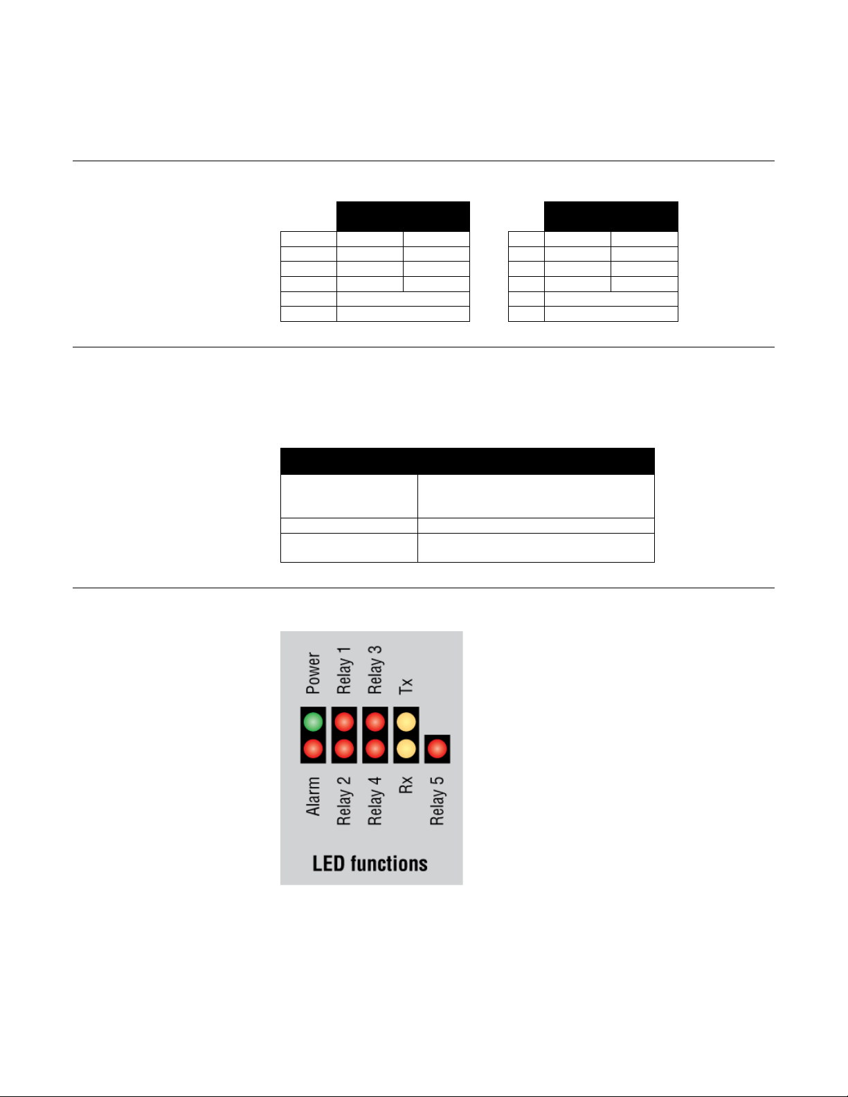
2.3 nVent RAYCHEM NGC-30-CRM/-CRMS LED Functions 4
Section − 3 Main Screen and Events/Alarms Navigation 5
3.1 Navigating Between Screens 5
3.2 Navigation Buttons 5
3.3 Navigational Header 6
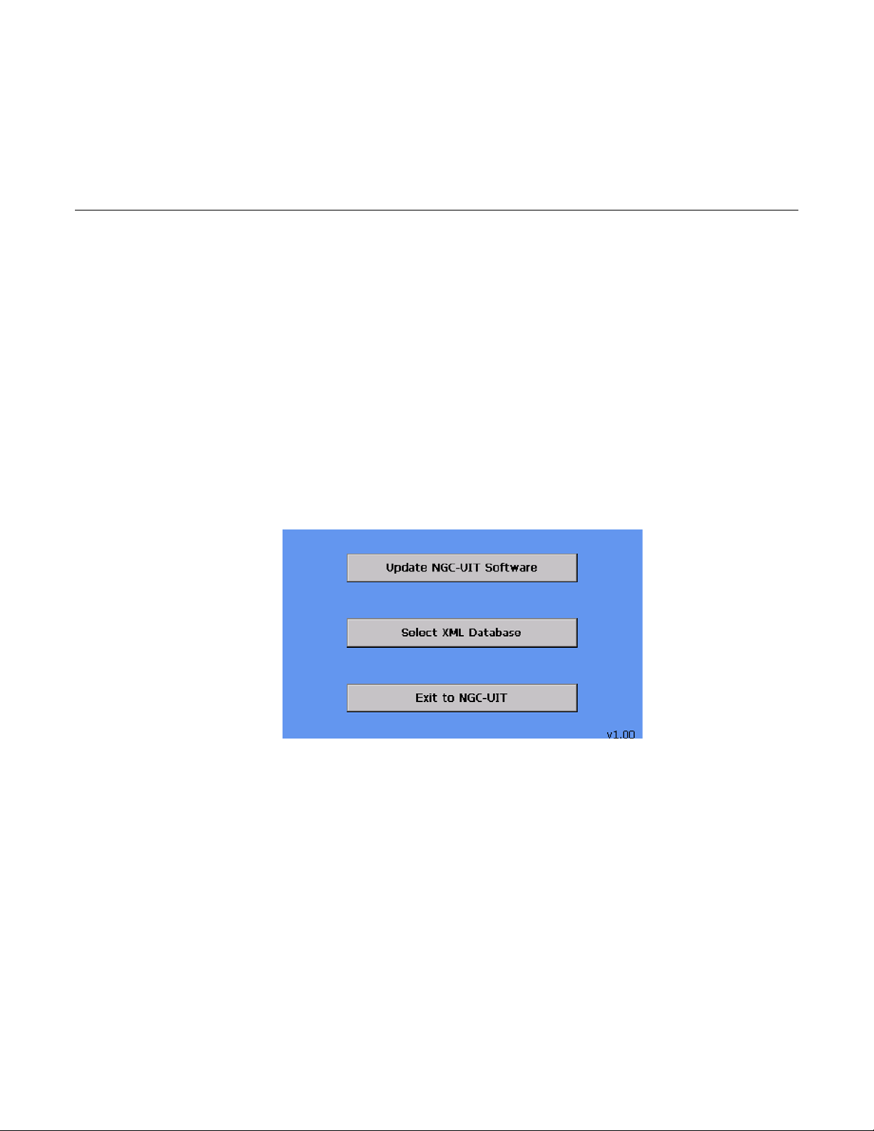
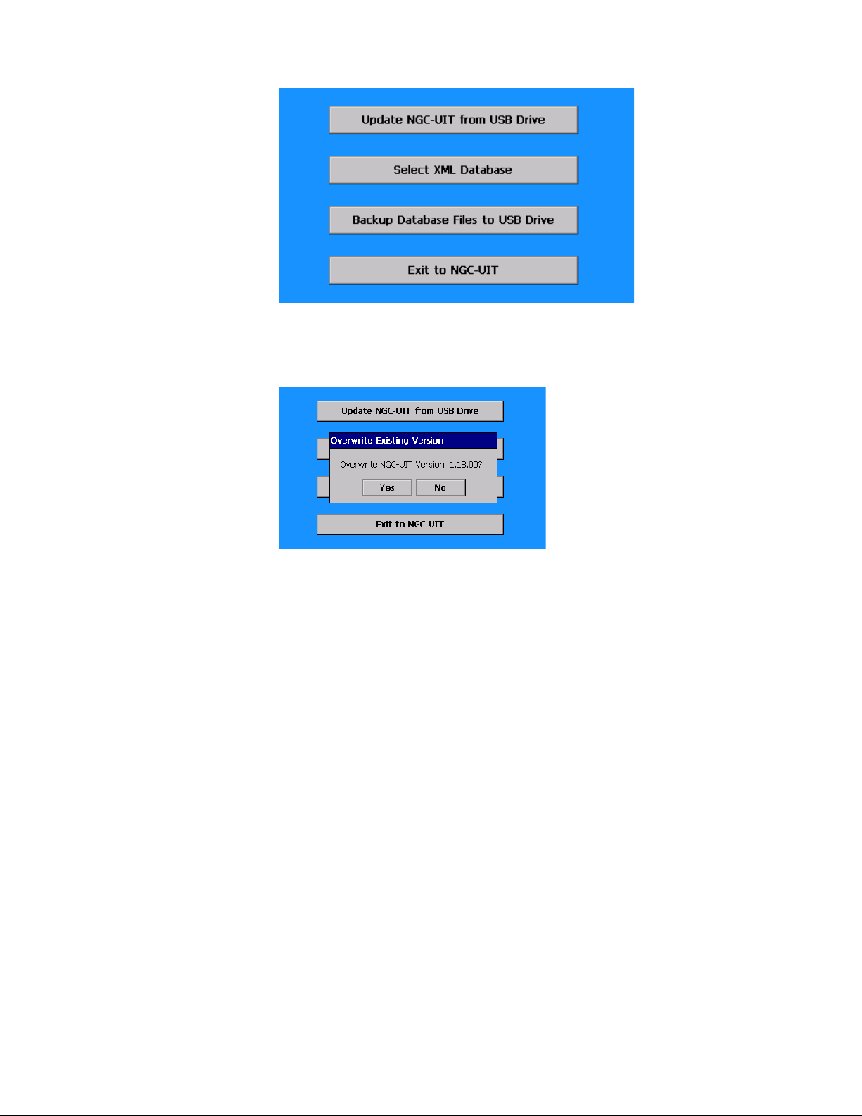
Section − 4 nVent RAYCHEM NGC-UIT Software Upgrade Process 7
Section − 5 Setting NGC-UIT Program to Demo Mode 9
Section − 6 Quick Start for Demo 11
6.1 Setup of Circuit 3 11
6.1.1 Circuit 3 Setup Complete Confirmation 24
6.1.2 Circuit 5 Voltage Monitoring – Status Only 25
6.2 Creating Alarms 25
6.2.1 Ground-Fault Trip Alarm 25
6.2.2 Low and High Temperature Alarms 27
6.2.3 Low and High Current Alarms 30
6.2.4 High Current Alarm 31
6.2.5 Ground-Fault Alarm 33
6.2.6 Communication Alarm 35
6.3 Proportional Control Demonstration 36
6.3.1 Circuit 1- Using the LED Light 36
Appendix A. PLI Demo Unit 37
PLI Demo Unit - Connection Diagram 38
PLI Box 39
Transformer 39
Power Line Carrier Interface Module (PLI) 39
PLI Demo Voltage Adjustment 40
Pipe Sculpture 42
SES Transmitter 43
SPC Transmitter 43