nVent RAYCHEM NGC-30 User manual

nVent.com | 1
NGC-30
LUNCH AND LEARN MANUAL

nVent.com | 2
Table of Contents
Connection Diagram 3
Connecting to the Demo Unit ........................................................................................... 3
Information Charts 4
RTD Switch Settings ......................................................................................................... 4
Color Coding of Main Screen ........................................................................................... 4
nVent RAYCHEM NGC-30-CRM/-CRMS LED Functions.................................................. 4
Getting Started 5
Demonstration Flow ......................................................................................................... 5
Set the Stage ..................................................................................................................... 6
The Main Screen ............................................................................................................... 8
Get Someone Involved...................................................................................................... 9
Program a Circuit............................................................................................................ 10
Alarms and the Events Lists........................................................................................... 16
The Network Tab............................................................................................................. 17
Security............................................................................................................................ 19

nVent.com | 3
Connection Diagram
Connecting to the Demo Unit
See the nVent RAYCHEM NGC-30 Demo Unit Connection Guide for instructions on how to
connect your computer to the NGC-30 Demo Unit and run the CER Host Program and RAYCHEM
Supervisor.

nVent.com | 4
Information Charts
(Inside the NGC-30 cover)
RTD Switch Settings
Circuit
#3
Circuit
#4
A
113ºF
45ºC
A
112ºF
44ºC
B
141ºF
61ºC
B
140ºF
60ºC
C
152ºF
67ºC
C
153ºF
67ºC
D
182ºF
83ºC
D
183ºF
84ºC
E
Shorted
E
Shorted
F
Open
F
Open
Color Coding of Main Screen
The data in the °F/°C, Amps, and G.F. columns are displayed in color to identify their current
state.
Color Description
Green When heater is energized (status
On), within Normal range of setup
parameters
Red In Alarm condition
Orange
(°F/°C only)
Temperature not within setpoint +
Dead Band range
NGC-30-CRM/-CRMS LED Functions

nVent.com | 5
Getting Started
Demonstration Flow
The recommended flow of the NGC-30 demonstration is as follows. You can experiment or
adjust based on the audience questions or your read on their interest level.
•Set the Stage
Explain what it is that their looking at. Many people think this is an actual panel and
not a demonstration unit.
•Show the Main Screen
Explain the main screen and what it shows.
•Get Someone Involved
Pick someone from the audience and have them come up to interface with the
demo unit.
•Program a Circuit
The idea here is to provide as little guidance as possible and let the person “figure it
out” in real time. This shows the audience how easy the UIT makes interacting with
the system.
•Show an Alarm and the Events List Features
This allows us to emphasize the alarm notification features and that everything is in
plain language, not secret codes.
•The Network Tab
It demonstrates the full range of information here emphasizes the tools built into
the unit to help shorten the commissioning cycle.
•Security
It shows the built-in password function is important so that the customer feels
comfortable that anyone can’t just wander up to the UIT and change settings at
random.

nVent.com | 6
Set the Stage
Explain that this is a demonstration model of the NGC-30 platform and not a real panel.
Go through the elements of the demo unit and point out the following:
•Touch screen interface – revolutionizes interaction with the system and makes it
incredibly easy.
•CRMS card – this is the control circuitry. Five heat tracing circuits are supported on
one card.
oNetwork Interfaces – point out the Ethernet, nVent RAYCHEM RS-485 and
RS-232 connections and that each UIT in the field supports each of these.
oRS-232 – for at the panel interface if you’re using nVent RAYCHEM
Supervisor on a laptop
oRS-485 – the main communications interface between the control boards,
the UIT and accessories like the nVent RAYCHEM RMM2 and PLI.
•Demonstration panel – these are the adjustment knobs and are used to show the
system response to changes in temperature, line current and ground-fault current.
IMPORTANT: Typically there is no time to demonstrate the system response using the
demonstration panel features and I don’t make an effort to show this unless the audience
wants to see it specifically or there is a lot of time left.

nVent.com | 7
CRMS Control
Board
Touch Screen
Demonstration
Panel

nVent.com | 8
The Main Screen
The Main screen displays the summarized information for each circuit. Point out:
•Full text circuit ID for easy identification of the circuit.
•Measured pipe temperature so that you know what the present status is of the pipe
temperature.
oAt this point, touch the UIT on one of the circuits to bring up the Status
screen for that circuit.
oMention that if you want to know any additional information on that
particular circuit, touch it and the applicable Status screen will appear with
additional information.
oThen touch the Main tab to return to the Main screen
•Setpoint is listed so that you can compare the measured temperature to the
setpoint. Because no-one knows what the target temperature is from memory.
•For circuits with On/Off control mode, the deadband setting is displayed.
•Then the line current and ground-fault currents are displayed
•The status of the heat tracing circuit is also shown – is it on or off at that moment.
•Finally, the status of the 3 internal alarm relays is displayed. If an alarm is active on
any one of those relays, then the displayed square will be red. All green means
everything is good.
Figure 1: Show the Main Screen

nVent.com | 9
Get Someone Involved
At this point you should get someone from the audience up to actually use the touch screen
for the rest of the demonstration.
Good candidates are usually young engineers.
•They are more familiar with this type of interface.
•They are more interested in new “cool” technology like this.
•Their boss, if attending, will usually pressure them go up.
•They’re the ones who will talk about this to their peers if we make a good
impression.
Regardless, you need to get someone to run the touch screen instead of you. The touch
screen interface is a primary differentiator for us and you need to have the audience walk
away feeling like they could figure it out easily and be excited about specing it into their
present or next contract.

nVent.com | 10
Program a Circuit
Now it’s time to have your assistant program a circuit.
The approach is to provide guidance to the person operating the demo unit and letting them
figure out how to accomplish what you’ve asked them to do. The real power of this exercise
is in the audience seeing how little guidance is needed to actually use our system.
Suggestion:
Use keywords in your questions – when you ask someone to do a task, include a word that
they would see on the screen which would give them a clue as to what to click on to
accomplish your task.
•Example: Instead of asking them to “Program a circuit”, ask them “How would you
set up a circuit? What do you think you would do?” This guides them towards
touching the Setup tab at the top of the screen.
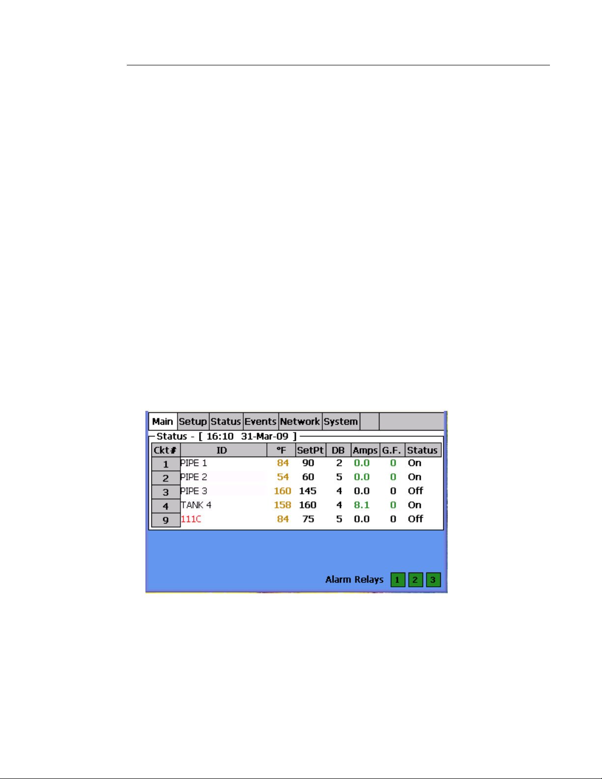
Step 1:
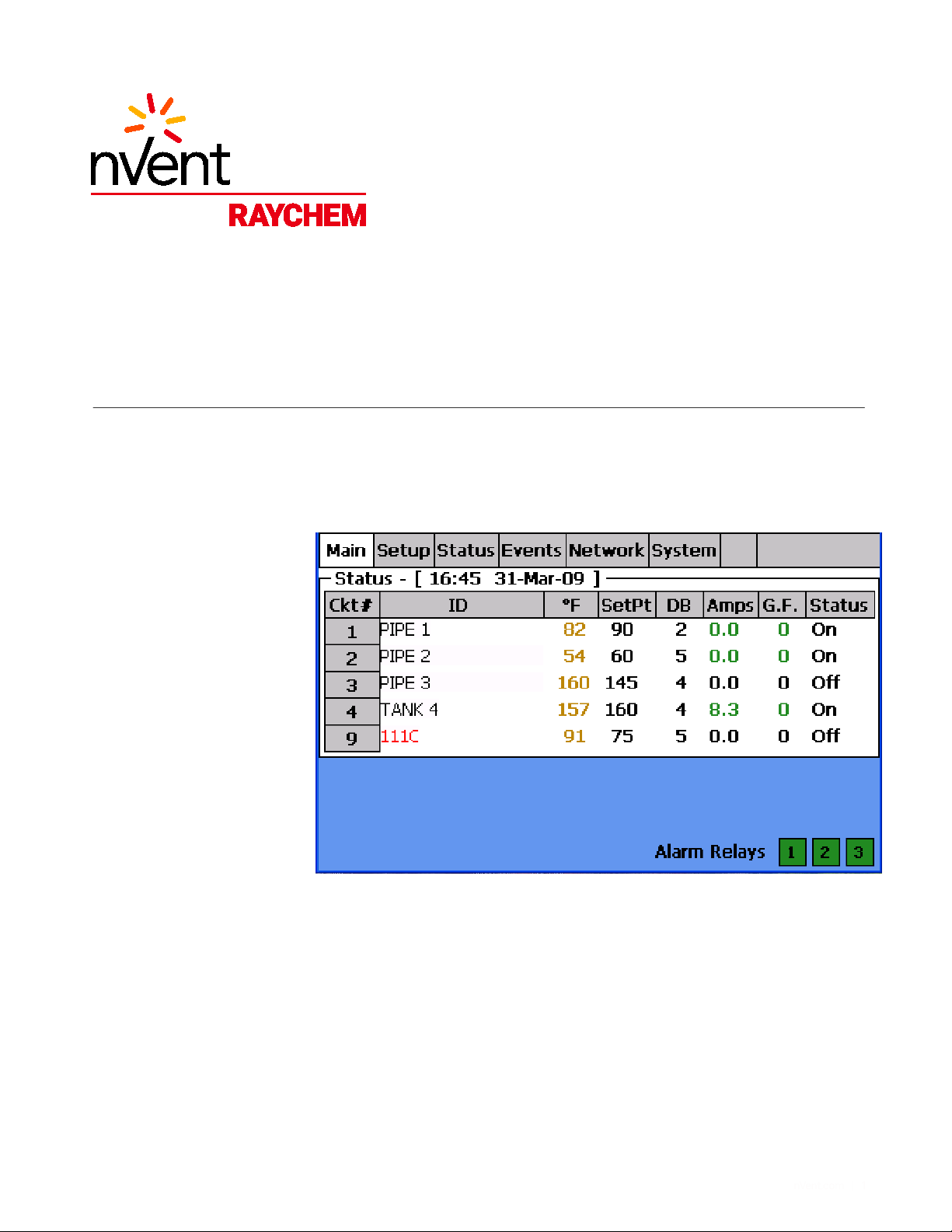
The demo unit should have the Main screen on display. If not, instruct the user on how to get
there.
•“Touch the Main tab”.
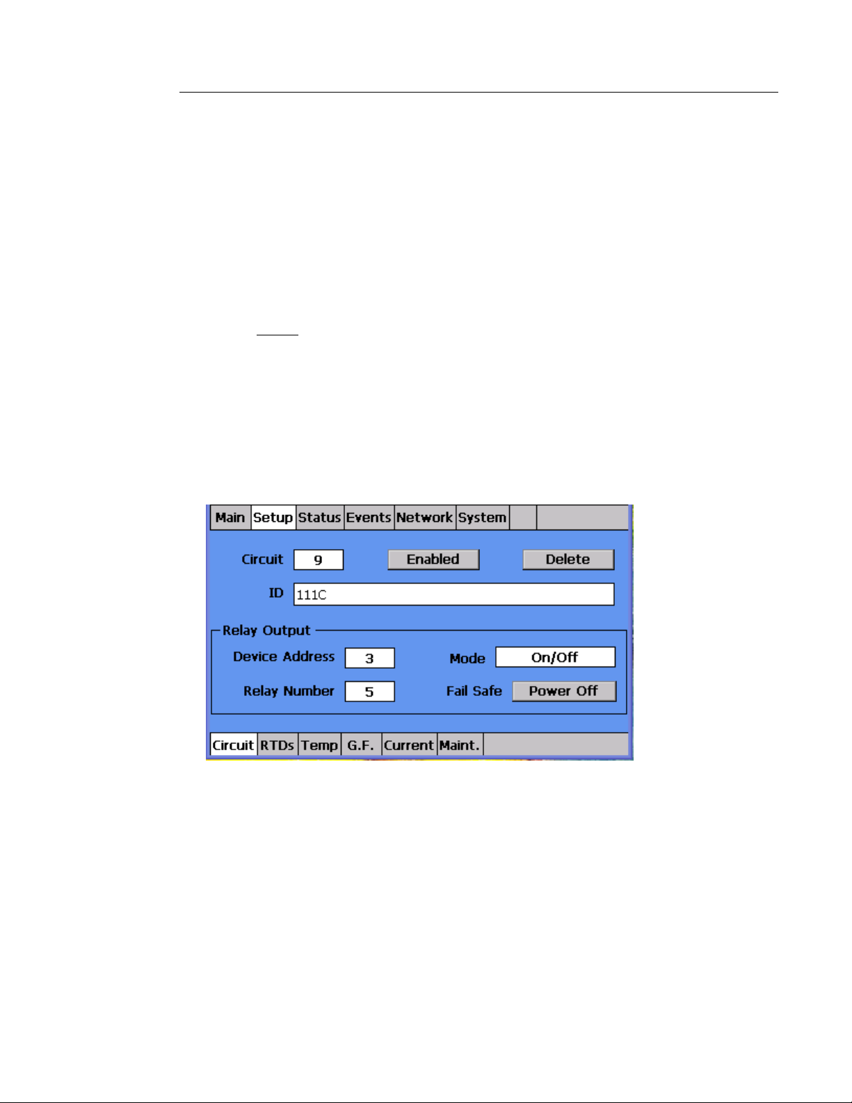
Figure 2: The Setup Screen
Preface the activity with a version of the following script:
“The NGC system User Interface Terminal is designed to be an intuitive interface to the heat-
tracing system. Its design uses plain language and is based on standard PC navigation set
up and techniques. Data is entered similar to texting on your cell phone. So if you use a
computer or a cell phone, the interface with the NGC User Interface Terminal is very similar.
OK, so let’s get started.

nVent.com | 11
Step 2: Navigate to the Setup Screen
“OK, user, we want to set up a circuit, what is the first thing you think you’d do from this
screen?”
•The user should choose the Setup tab on the top of the screen.
•If they are having trouble say:
o“Since this is a tab based architecture, which tab would you select to set up
a circuit?”
Step 3: Select a circuit number
“Now we need to add a circuit, let’s add circuit #5. How would you do that?”
•Hopefully, the user touches the white box to the right of the Circuit text. This will
bring up the circuit number pop up box.
•If the user is touching the word “Circuit” instead of the white box, then address the
whole group and say; “Any time that you want to make an entry, touching the white
boxes gets you to that information entry point.”
•If circuit #5 already exists, have the user select another number.
Figure 3: Entering the Circuit Number
“Next, we want to create a label or ID for that circuit. How would you do that? Pick any name
you want”.
•User should touch the white box next to the word “ID”. This will bring up the ID text
entry pop up box.
•Text is entered using multiple touches of the buttons to select the desired letter or
number. This is exactly the way it works for texting on your cell phone.
•Once the text is entered, the user should touch the Enter button.

nVent.com | 12
Figure 4: Entering the Circuit ID
“Most panels will have multiple control cards so you have to define the address for the
control board which you want to assign the circuit to. Where would you start?”
•User should touch the white box next to the words “Device Address”.
•If you don’t know the CRM card device address, instruct the user to go to the
Network screen and get the device address from there. Then go back to the setup
menu.
“Now you need to assign this circuit to a relay on the CRMS board. What do you do to do
that?”
•User should touch the white box next to the word “Relay”.
•Relay assignment pop up box should appear and at least one relay should be
unassigned.
•User should select one of the unassigned relays. At that point the ID text will
automatically be dropped into the unassigned box that was selected and all that has
to be done to complete this is for the user to touch the Next button.
•If all the relays are assigned, simply instruct the user to “Cancel” out of the Assign
Relay Number screen, select a circuit number and then touch the “Delete” button.
Confirm the circuit deletion by touching “Yes”.
•Then go back to the circuit number you are programming, select relay number and
there should be an “Unassigned” relay.
•User should select the unassigned relays. At that point the ID text will automatically
be dropped into the unassigned box that was selected and all that has to be done to
complete this is for the user to touch the Next button.

nVent.com | 13
Figure 5: Assigning a Relay Number
“Next we need to select a control mode.”
•User should touch the white box next to the word “Mode”.
•Advise the user to select On/Off mode for simplicity.
Figure 6: Select a Control Mode
“Now RTD’s must be assigned to this circuit.”
•Give the user some time to figure out how to get to the RTD screens before you
direct them to the bottom menu tabs.

nVent.com | 14
Figure 7: Assigning RTD’s
“The NGC-30 can have up to 4 RTD’s assigned as control points for the circuit. The system
will control (decide whether to turn on or off) based on the lowest measured temperature
value.
“RTD’s can be assigned from two different sources; hardwired into the CRM Control boards
or from an RMM2. So we first need to know the device address of the RTD source; either the
CRM card or the RMM2. This information can be found by going to the Network screen.”
•User should touch the Network tab on the top menu.
•Note the addresses for the CRM card and the RMM2 and then have the user return
to the Setup/RTD menu.
•Once back at the Setup/RTD screen, have the user enter one of the device
addresses in the device box.
•The user should now enter an RTD Number for the corresponding device address.
oIf for either the device address or the RTD Number, the user enters a number
and that number doesn’t get displayed on screen, it is probably the case that
the user has entered an incorrect number. This is one of the “idiot-proofing”
features of the C&M system.
At this point in the demonstration, I usually start to move things along more quickly and
show the group the remaining screens without having the user change or enter any data. The
group usually has an understanding of the setup process and the touch screen interface.
However, if as I instruct the user to go through the remaining Setup screens, they begin
making changes on their own, I never discourage it because it shows the group how quickly
someone can pick this up.

nVent.com | 15
“The temperature set points and alarm thresholds are set in the Temp menu.”
•The user usually goes to the Temp menu and may begin making changes,
•I usually only point out that this is where the data is entered for temperature and
then move on.
Figure 8: Setting Temperature Values
“Next, it’s the Ground-Fault screen. Notice that there are two entries, one for an alarm and
one for trip. We added the alarm to give operators and indication that a ground fault problem
may be coming so that they can put it on their schedule to investigate. Without this feature,
the control system would just shut down the heat tracing when the trip threshold was
reached and now repair becomes critical. The Alarm feature helps manage these issues if
they occur without having the potential of shutting the plant down.”
•The user may change values here.
•I recommend giving the above speech and moving on.
Figure 8: Setting Ground-Fault Values

nVent.com | 16
“The current monitoring set points and alarm thresholds are set in the Current menu.”
•The user usually goes to the Current menu and may begin making changes.
•I usually only point out that this is where the data is entered for current and then
move on.
Figure 9: Setting Line Current Values
“Now let’s return to the Main screen. That’s all there is to setting up a circuit.”
•I usually point out how little direction was given to the person running the NGC-30
UIT, that entries were fairly intuitive and just by looking at the screens that person
could figure out what they were supposed to do.
•Make the point that this is one of the most valuable things about the NGC-30
systems – it is an intuitive interface that uses plain language and is easy for users
to figure out.
Alarms and the Events Lists
This section shows the group how the NGC-30 notifies the user of alarm conditions and how
to use the Events list to see active or specific alarms.
•Instruct the user to go to push the red Ground-Fault Trip button on the left side of
the demo unit.
•The red Circuit power indicator light should go off and the red “Aknowledge” fault
indication section of the UIT screen should illuminate.
“What we just did was to induce a ground current fault in circuit 1. The NGC-30 system
responds by first disabling the circuit and then posting the red fault indicator with the word
“Aknowledge” in it. The UIT display also changes the circuit #1 text to red to provide a visual
indication that this is where the problem is.”
“Touching the fault indicator area will bring you to the Events screen where this fault is
displayed in flashing red. It is displayed in flashing red because it is considered an operator
safety related fault. This means that if the fault goes away, the circuit does not
automatically turn on, it must be manually reset.”

nVent.com | 17
“If you touch the flashing red area, the NGC-30 system will take you directly to the circuit 1
Status screen. The Alarm Reset button is highlighted in red and you can only re-energize the
circuit by pressing that button.”
•Instruct the user to press the Alarm Reset button if they have not already done so.
•Circuit 1 should turn back on.
“Let’s go back and look at the Events list. The Events list stores up to 2,000 entries. Once it
exceeds that number, it drops out the first entry and adds the most recent event. The entries
are all in plain language, easy to understand and any fault values have associated numbers
displayed, like we saw for the ground-fault event. Also, each event has a time and date
stamp assigned and the circuit number is referenced. So no secret codes to decipher,
everything is straightforward.”
“You can scroll up and down using the arrows at the bottom of the screen. Also, there is a
built in sorting function. If you touch the “Event, Press for Alarms” button, the various fault
types will be sorted and displayed. Touch once and all the active alarms are displayed. This
is very useful when working in the panel so that you don’t have to scroll around the full list of
2,000 events to see what you want.”
“The Events list can also be downloaded either to a USB stick or via RAYCHEM Supervisor so
you can keep a history or archive if you like.”
Figure 10: The Events Screen
The Network Tab
The Network tab is a great asset when commissioning a system because it allows the heat-
tracing documentation to be compared directly to how the NGC-30 system thinks it is set up.
The value of this is that connections, addressing, relay and RTD assignments can be
checked prior to reviewing alarms. This significantly reduces the troubleshooting time,
especially with wiring.
The goal here is to show that the NGC-30 has built in tools that support the commissioning
of the panel and assist in troubleshooting.
“Let’s look at the Network tab next. This is a really powerful tool that is built into the NGC-30
system.”
•Instruct the user to touch the “Update Network” button. The UIT shows a search
progress bar.
“When the NGC-30 system is first powered on, the commissioning engineer can come to this
screen, hit the Update Network button and the NGC-UIT will go out and search its network to
see what is connected to it. Then it will display a list of the devices it sees, the address of
those devices and the resources associated with them. This is really powerful because
nothing ever gets wired up correctly the first time and you can spend a lot of time trying to

nVent.com | 18
guess what is causing an alarm when the information on these screens can tell you directly.
Using this screen, the commissioning engineer can take his paperwork and go through all of
the devices that are supposed to be in the system and compare that to what is listed on the
NGC-UIT screen. The device addresses can be checked along with the resources. The
resource information is great because it shows whether anything is missing. For example on
the RMM, all of the RTD’s that the NGC-UIT sees are listed. If you know that you are
supposed to have all of the RTD’s from 1 to 8, but you look at the list and #4 is missing, then
you know you have a wiring problem. So before you even begin looking at faults, you are
confident that at least all the devices are there. This is very powerful in reducing the time it
takes to commission the system.”
Figure 11: The Network Screen
“Going to the Relay menu tab shows what circuit is assigned to each relay on each CRM
control board. Again, this allows the engineers to quickly confirm that the circuits they think
are heating certain pipes are indeed controlling the heat tracing to those pipes.”
Figure 12: The Network/Relays Screen

nVent.com | 19
“The RTD menu tab shows which circuits are using which RTD’s. Because the NGC-30
system is so flexible, an RTD may be assigned to more than one circuit. This would be the
case for freeze protection for example where multiple circuits can control off one ambient
temperature RTD. Again, you can see how quickly and easily the RTD assignments can be
confirmed before start up.”
Figure 13: The Network/Relays Screen
“The information available in the Network screens can have a significant impact on reducing
commissioning time. You have confidence that the wiring and connections are good before
you turn the panel on and this will significantly reduce the number of alarms that are
generated when the panel is first turned on This is powerful, useful stuff which no one else
on the market has today.”
Security
This section addresses the security features of the NGC-30 System.
“The NGC-30 system incorporates two levels of passwords to protect the settings from
unauthorized change.”
•Instruct the user to go to the System/Password tab and press Yes or OK. But
caution them not to enter anything otherwise you may not be able to get back into
the unit.
“This is where passwords can be set. The Level 1 password prohibits changing of any
programmable values so that someone cannot simply walk up to the unit and start playing
with the settings. The Level 2 password is required to reset the Events list and exit the
operating system. Operators should never have to exit the UIT operating system though.”
“So the NGC-30 system has protection built in.”

nVent.com | 20
Figure 14: The System/Password Screen
At this point I ask if there are any questions as an hour has usually passed and the meeting
will begin breaking up. Anything you get asked that you don’t know the answer to, write
down and call product marketing. Feel free to try us via cell phone during the meeting if you
want!
Other manuals for NGC-30
2
Table of contents
Other nVent RAYCHEM Industrial Equipment manuals