Oakley Sound RM-4014 User manual

Oakley Sound Systems
5U Oakley Modular Series
RM-4014 Ring Modulator
PCB Issue 3
User Manual
3.0.0
Tony Allgood B.Eng PGCE
Oakley Sound Systems
CARLISLE
United Kingdom

The suggested 5U panel design. Note the slightly different spacing of the knobs compared
with the usual 41mm 5U Oakley standard.
2

Int oduction
This is the Use Manual fo the issue 3 RM-4014 Ring Modulato 5U module f om Oakley
Sound. This document contains an ove view of the ope ation of the unit and the calib ation
p ocedu e.
Fo the Builde 's Guide, which contains a basic int oduction to the boa d, a full pa ts list fo
the components needed to populate the boa d o boa ds, and a list of the va ious
inte connections, please visit the main p oject webpage at:
http://www.oakleysound.com/ ingmod.htm
Fo gene al info mation ega ding whe e to get pa ts and suggested pa t numbe s please see
ou useful Pa ts Guide at the p oject webpage o http://www.oakleysound.com/pa ts.pdf.
Fo gene al info mation on how to build ou modules, including ci cuit boa d population,
mounting f ont panel components and making up boa d inte connects please see ou gene ic
Const uction Guide at the p oject webpage o http://www.oakleysound.com/const uct.pdf.
3

The Oakley RM-4014 Ring Modulato
This is a vintage ing modulato design with bags of cha acte . It is based on the classic
ARP4014 sub-module which was used on the ARP2500 modula and ARP2600 semi-modula
synthesise s. The design has a fully disc ete co e but uses two op-amps fo input and output
amplification.
A ing modulato has two main inputs, usually called X and Y, and one output. The output
voltage is the p oduct of the two input voltages. In othe wo ds it multiplies the two input
signals togethe to p oduce a new and diffe ent sounding output. If you have two sine wave
input signals then the output will have both the sum and diffe ence f equencies. Fo example,
if X is a 440Hz sine wave and Y a 40Hz, you would get a 480Hz and a 400Hz sine wave f om
the output. Howeve , this is only eally t ue in a pe fect ing modulato , and this ing
modulato is not that. Each input has its own diffe ing non-linea ities o impe fections. This
g eatly adds to the cha acte of the esultant output.
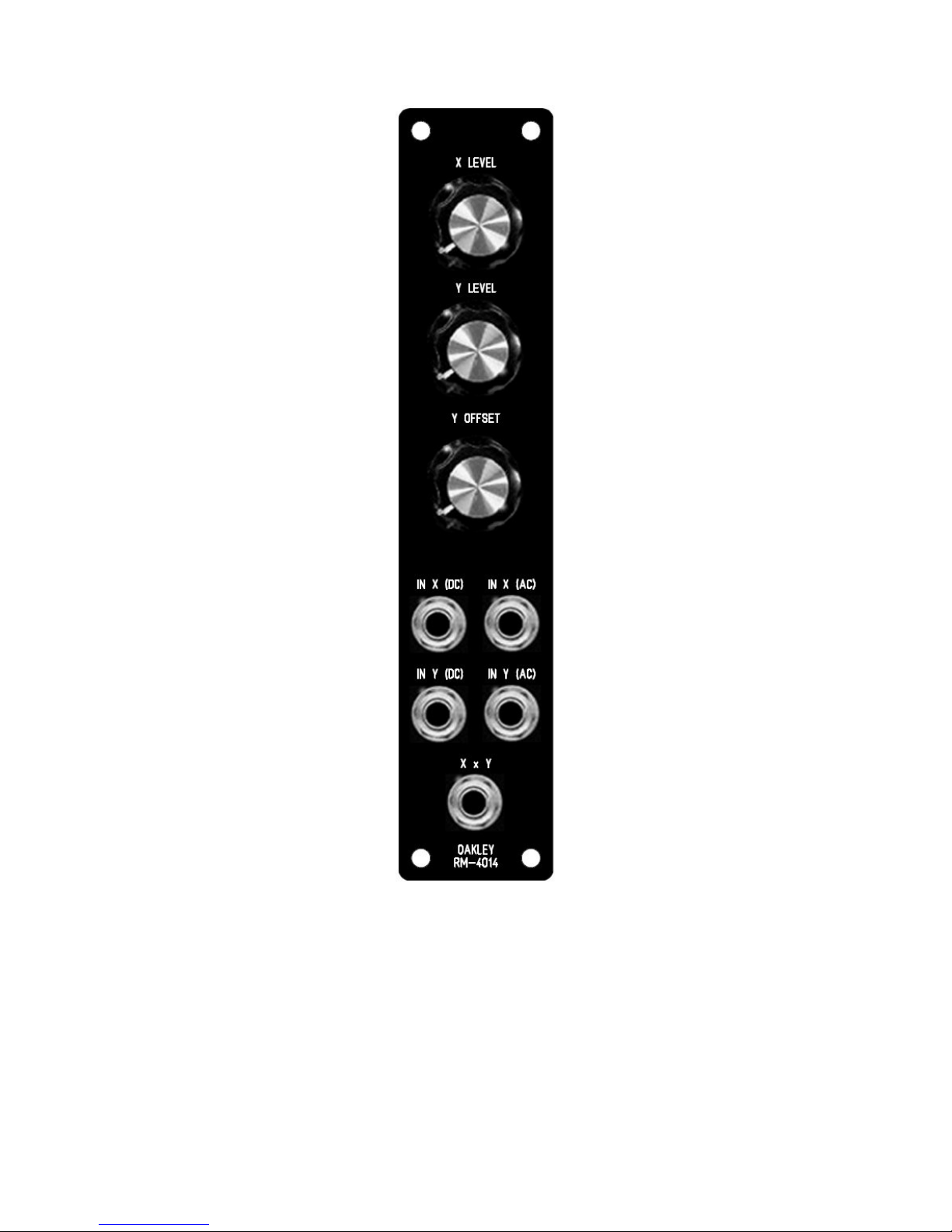
The Oakley Ring Modulato featu es th ee ota y cont ol pots. Each input has its own
attenuato , and the e's also a offset cont ol fo the Y input. In conjunction with the Y
attenuato , this thi d pot effectively acts as a wet-d y cont ol fo the X input. But because of
the non-linea ities inhe ent in the design it also acts in mo e subtle ways.
You can also use the Oakley Ring Mod as a standa d VCA. Just use the Y input as you CV
input and X will be shaped acco dingly. Each input can be eithe di ect coupled (DC) o high
pass filte ed (AC). The fo me allows DC and low f equency signals to be p ocessed. While
the latte p ovides a DC block to p ocess only alte nating f equencies. The standa d panel
design makes both types of input available with each having its own socket. You can use both
inputs on each of the X and Y inputs at the same time. Input signals will be summed togethe
so you can also use the RM-4014 as a simple audio mixe .
This is the prototype issue 1 R -4014 Ring odulator module behind a natural finish 1U wide OT
format Schaeffer panel.
4

Calib ation
The e a e th ee t imme s on the PCB which need adjusting co ectly to get the best out of the
ing modulato module. It is impo tant that you adjust these in you modula as the settings
a e affected by the powe supply voltages.
Allow the modula and ing modulato to wa m up fo 15 minutes.
BAL1: Tu n down X LEVEL and Y LEVEL pots to thei minimum settings. Tu n the Y
OFFSET pot to its maximum level. Measu e the output voltage f om the output socket with a
good digital voltmete . Adjust BAL1 until the output voltage is 0.000V +/- 5mV.
BAL2: Inse t a t iangle wave signal at 440Hz to the IN Y AC input. Tu n down the Y
OFFSET pot to its minimum setting. Tu n up the Y LEVEL to full. If you have a 'scope then
adjust BAL2 until the signal seen at the output socket is minimised as much as possible. It will
not go away completely. If you haven't got a scope then use you ea s with you monito ing
amp tu ned up somewhat. Adjust BAL2 until the sound f om the output socket is at its
smallest level. You will not get id of it completely, the ing modulato is not pe fect and as
such it will leak o bleedth ough. Once you have done this emembe to tu n you amp down if
you have tu ned it up high.
GAIN: Ensu e that the Y LEVEL is set to minimum, but the othe two pots to thei
maximum. Inse t an audio signal into IN X (DC) and adjust GAIN so that the output signal is
at the same level o volume as the input. That is, if you have a 5V peak signal inse ted into IN
X, then you should adjust GAIN fo a 5V peak signal at the output.
Once that is completed the unit is eady to be used to make music, o just daft noises...
5

Final Comments
I hope you enjoy using the Oakley Ring Modulato module.
If you have any p oblems with the module, an excellent sou ce of suppo t is the Oakley Sound
Fo um at Muffwiggle .com. Paul Da low and I a e on this g oup, as well as many othe use s
and builde s of Oakley modules.
If you have a comment about this use manual, o have a found a mistake in it, then please do
let me know.
Last but not least, can I say a big thank you to all of you who helped and inspi ed me. Thanks
especially to all those nice people on the Synth-diy and Analogue Heaven mailing lists and
those at Muffwiggle .com.
Tony Allgood at Oakley Sound
Cumb ia, UK
© July 2011
No pa t of this document may be copied by whateve means without my pe mission.
6
Table of contents