Oakton pH/CON 510 series User manual

pH/mV/Conductivity/TDS/°C/°F meter
ON/OFF
MEAS
HOLD
▲
▼
CAL
MODE
SET
pH/CON 510 series
RANGE
ENTER
pH/CON510
BenchtopMeter
WD-35610-10, -12, -15, -17
pH/CON510meter
10/00 ©2000 68X090817

return of
items
warranty
accessories
specifications
appendixes
troubleshooting
electrode
care
measurement
calibration
starting up
Starting up ..........................................................................4-8
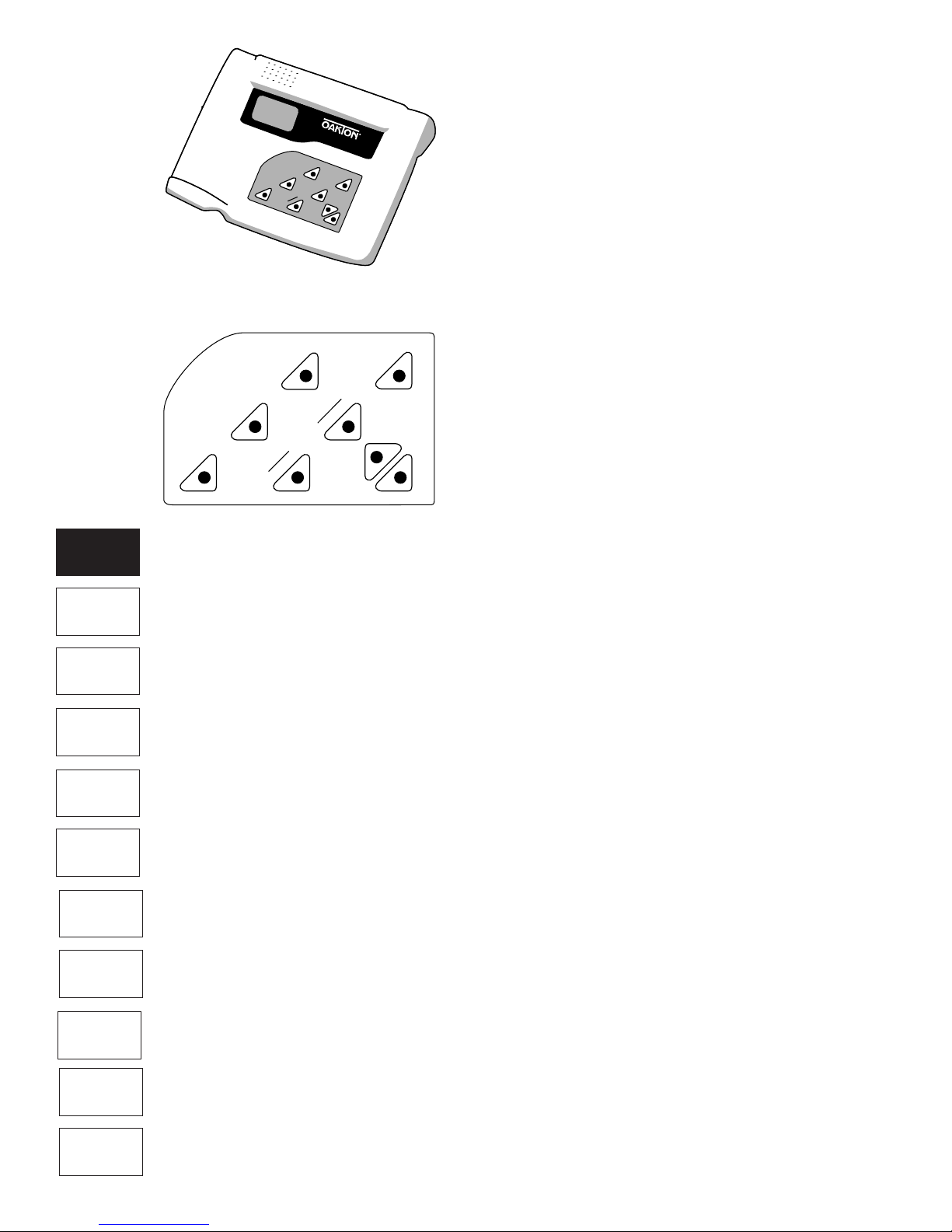
Keypad ..............................................................................4
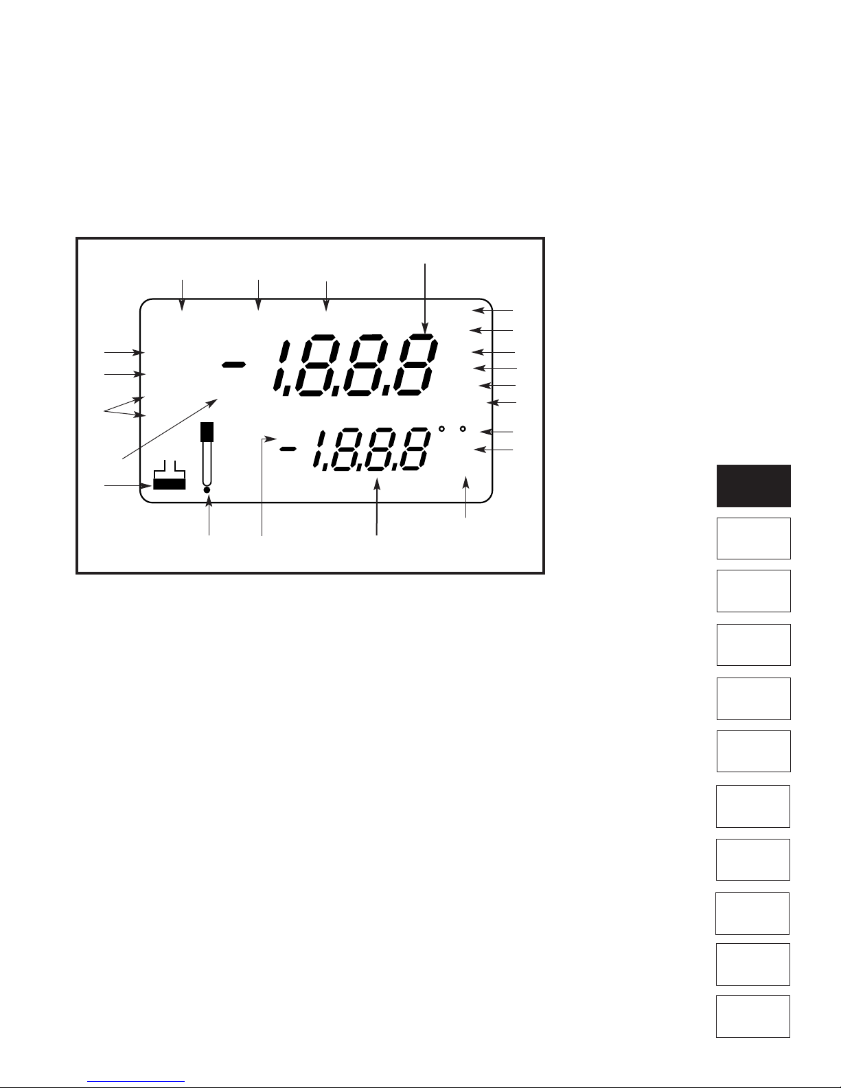
Display ..............................................................................5
Electrode holder arm ....................................................6-7
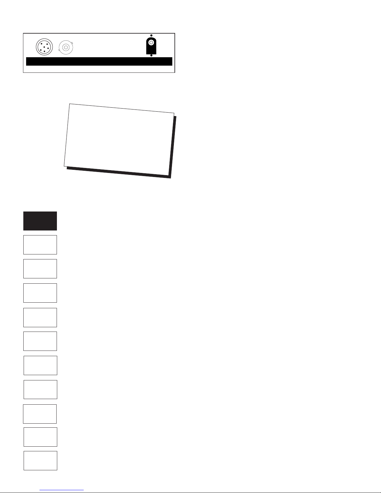
Probe connections............................................................8
Power connections ..........................................................8
Calibration ..........................................................................9-14
Important information on meter calibration ....................9
pH calibration ............................................................10-11
Conductivity/TDS calibration......................................12-13
Temperature calibration..................................................14
Measurement....................................................................15-21
pH measurements..........................................................15
mV measurements ........................................................16
Conductivity /TDS measurements ................................17
HOLD function/Ready indicator/Auto endpoint ............18
Using manual ranging function: conductivity/TDS ........19
Selecting manual temperature compensation:
conductivity /TDS......................................................20
Selecting a manual temperature compensation value..21
Advanced Setup mode..................................................23-37
Advanced setup mode overview..............................23-25
P1.0: Viewing previous pH calibration data ..................26
P2.0: Viewing pH electrode data....................................27
P3.0: pH configuration ..............................................28-29
P3.1: Ready indicator and auto endpoint functions 28
P3.2: Selecting number of pH calibration points ....28
P3.3: Selecting NIST or USA buffer sets ................29
P3.4: Selecting °C or °F............................................29
P4.0: Resetting to factory default settings (pH) ............30
P5.0: Viewing previous con./TDS calibration data ........31
P6.0: Viewing con./TDS probe data ..............................32
P7.0: Conductivity/TDS configuration ......................33-35
P7.1: Ready indicator and auto endpoint functions 33
P7.2: Selecting °C or °F............................................34
P7.3: Selecting Automatic/Manual temp. comp. ....34
P7.4: Setting the TDS factor ....................................35
P8.0: Temperature settings............................................36
P8.1: Selecting the temperature coefficient............36
P8.2: Selecting the normalization temperature ......36
P9.0: Resetting to factory default settings (con./TDS)..37
Probe Care ..................................................................................38-39
Electrode activation ........................................................38
Electrode maintenance ..................................................38
Storing pH/ORP electrodes............................................38
Electrode cleaning ..........................................................39
Conductivity/TDS probe care..........................................39
Troubleshooting ..............................................................40-41
Error messages ..............................................................40
Troubleshooting ..............................................................41
Specifications........................................................................42
Accessories ..........................................................................43
Appendix 1: Conductivity to TDS conversion factors ....44
Appendix 2: Calculating temperature coefficients ........45
Appendix 3: pH and temperature......................................46
Appendix 4: Meter factory default settings ....................47
Warranty ................................................................................48
Return of Items....................................................................48
3
Quick tip
let the mini table of contents in the outer
margins of this manual guide you instantly to
the right section
setup
mode
Tableofcontents

4
pH/mV/Conductivity/TDS/°C/°F meter
ON/OFF
MEAS
HOLD
▲
▼
CAL
MODE
SET
1.Startingup
Thank you for purchasing an OAKTON®pH/CON 510
benchtop meter. This multiparameter meter reads pH, mV,
Conductivity, Total Dissolved Solids (TDS), and temperature
(°C or °F). It is microprocessor controlled, user-friendly and
reliable.
Keypad
See Figure 1.
A large membrane keypad makes the meter easy to use.
Names and symbols describe the function button controls.
ON/OFF
Powers the meter ON/OFF. When the meter is switched on,
it starts in the mode the meter was last in when powered
down.
ENTER/RANGE
ENTER Press to confirm values in Calibration mode and to
confirm selections in Setup mode.
RANGE Press to switch to manual ranging in Conductivity or
TDS mode.
CAL/MEAS
Toggles user between Calibration and Measurement mode.
Example: If you are in pH measurement mode, press
CAL/MEAS to enter pH calibration mode.
NOTE: Temperature calibration is available from pH, TDS, or
Conductivity calibration mode; see page 14 for directions.
In Set up mode
:
Press CAL/MEAS to return to main menu
from sub menus. Press CAL/MEAS again to return to mea-
surement mode from main menu.
HOLD
Freezes the measured reading. To activate, press HOLD
while in measurement mode. To release, press HOLD again.
NOTE: When auto endpoint feature is switched on, meter
automatically holds reading after 5 seconds of stability. The
HOLD indicator appears on the display. Press HOLD to
release auto endpoint feature.
MODE
Measurement:
Press MODE to toggle between pH, mV,
conductivity and TDS.
Calibration:
In calibration mode, press MODE to access
temperature calibration.
SET
Enters advanced set up mode. SETUP mode lets you
customize meter preferences and defaults, and view
calibration and probe data.
▲/▼
Press in Setup mode to scroll through subgroups. Also lets
you increment/decrement the values in the conductivity, TDS
and temperature calibration modes.
Figure 1
ON/OFF
RANGE
HOLD
▲
▼
ENTER
MODE
SET
MEAS
CAL
troubleshooting
electrode
care
measurement
calibration
starting up
setup
mode
return of
items
warranty
accessories
specifications
appendixes

5
Figure 2
Display
See Figure 2.
The OAKTON®pH/CON 510 meter features a large dual
display that shows the measured parameter in the primary
display, plus temperature in °C or °F in the secondary
display. It also features mode annunciators that describe
the meter’s functions.
mS
ATC
READY
MEAS CAL
HOLD
ERR F
SETUP
ON
OFF C
µS
pH
mV
pH
ppt
ppm
K=
Primary display
Secondary display
3.
2.
19.
18.
13.
15.
14.
12.
1.
17.
16.
4.
6.
5.
9.
11.
10
7.
8.
1. SETup mode indicator
2. MEASurement mode
indicator
3. CALibration indicator
4. mV indicator
5. pH measurement indicator
6. Millisiemens indicator
7. Microsiemens indicator
8. Parts per thousand (Total
Dissolved Solids) indicator
9. Parts per million (Total
Dissolved Solids) indicator
10. Temperature indicators
11. pH setup indicator
12. Automatic Temperature
Compensation indicator
13. ERRor indicator
14. Probe indicator
15. Calibration indicator
16. Cell constant indicator
17. ON/OFF indicator
18. HOLD indicator
19. READY indicator
troubleshooting
electrode
care
measurement
calibration
starting up
setup
mode
return of
items
warranty
accessories
specifications
appendixes

6
ElectrodeHolderArm
The electrode holder is included in the same
box as the meter.
Toattachtheelectrodeholdertothemeter:
1. The electrode holder base attached to
the bottom of the meter comes in the ship-
ping position.
See Figure 3.
2. Use a Phillips screwdriver to remove the
screw holding the electrode holder in ship-
ping position.
See Figure 3.
3. Slide the electrode base away from the
meter until the second screw slot lines
up with the original screw hole. Use the
screw removed earlier to secure
electrode holder base into position.
See Figure 4.
4. The electrode holder arm is reversible. If
desired, remove screw holding electrode
holder base and slide base out of
brackets. Slide base into brackets on oppo-
site side and replace screw.
See Figure 5.
Bottom of meter
Figure 3
Figure 4
Figure 5
Shipping position
Bottom of meter
Bottom of meter
troubleshooting
electrode
care
measurement
calibration
starting up
setup
mode
return of
items
warranty
accessories
specifications
appendixes

7
Figure 6
Figure 7
5. To install the electrode arm, turn meter back
to the upright position.
See Figure 6.
6. Line up the hole on the base of the
electrode holder arm with the peg on
the electrode holder base. Slide the hole
securely onto the electrode holder base.
See Figure 7.
The electrode arm is now ready to swing into
desired position.
See Figure 8.
pH/mV/Conductivity/TDS/°C/°F meter
ON/OFF
MEAS
HOLD
▲
▼
CAL
MODE
SET
pH/CON 510 series
RANGE
ENTER
The electrode arm is
now ready to swing into
desired position.
Figure 8
troubleshooting
electrode
care
measurement
calibration
starting up
setup
mode
return of
items
warranty
accessories
specifications
appendixes

8
Probeconnections
See Figure 9 .
Your meter includes two probes:
• pH electrode with BNC connector
• conductivity/TDS/temperature probe with a notched
6-pin connector
The temperature sensing element built into the conductiv-
ity/TDS probe will also compensate for pH readings as long
as both probes are in your solution at the same time.
If you want to use an “All in One” pH probe with a built-in
temperature element, or if you want to use a separate
temperature probe, you will need to disconnect the
conductivity/TDS probe to allow for connection of the
separate temperature sensor.
You can use any standard pH, mV (ORP) or Ion Selective
electrode with a BNC connector with this meter.
Conductivity/TDS probes, “All in One” pH electrodes with a
built-in temperature element, and separate temperature
probes require a probe with a notched 6-pin connector.
For replacement probes, see the “Accessories” section,
page 43.
To connect the pH electrode:
1. Slide the BNC connector of the probe over the BNC
connector socket on the meter. Make sure the slots of
the connector are in line with the posts of the socket.
Rotate and push the connector clockwise until it locks.
2. To remove probe, push and rotate the connector
counterclockwise. While holding onto the metal part of
the connector, pull probe away from the meter.
To connect the conductivity/TDS/temperature probe:
1. Line up the notch and 6 pins on the meter with the holes
in the 6-pin connector. Push down and turn the locking ring
clockwise to lock into place.
2. To remove probe, turn locking ring counterclockwise on
the probe connector. Pull probe away from the meter.
NOTE: follow the same directions to connect an optional sep-
arate temperature element.
Powerconnections
See Figure 9 .
Your meter includes an AC to DC adapter:
To connect the AC adapter:
1. Slide the phono plug of the AC adapter into the “DC” slot
on the back of the meter.
Attention!
Do not get water on the connectors
during operation. Avoid touching
the connector with soiled or wet
hands. Do not pull on the probe
cord or the probe wires might
disconnect.
Figure 9
CON/TEMP pH DC
troubleshooting
electrode
care
measurement
calibration
starting up
setup
mode
return of
items
warranty
accessories
specifications
appendixes

9
2.Calibration
ImportantInformationonMeterCalibration
When you recalibrate your meter, old calibration points are
replaced on a “point by point” basis in pH, and on a “range
by range” basis in conductivity or TDS.
For example:
• pH: if you previously calibrated your meter at pH 4.01,
7.00, and 10.01, and you recalibrate at pH 7.00, the meter
retains the old calibration data at pH 4.01 and pH 10.01.
• Conductivity/TDS: if you previously calibrated your meter at
1413 µS in the 0 to 1999 µS range and you recalibrate at
1500 µS (also in the 0 to 1999 µS range), the meter will
replace the old calibration data (1413 µS) in that range. The
meter will retain all calibration data in other ranges.
Note that if you calibrate a TDS value in an equivalent
conductivity range, the TDS value will replace the previous
conductivity value, and vice versa.
To view current calibration points:
• pH: Program P1.0 in the SETUP section, page 26.
• Conductivity/TDS: Program P5.0 in the SETUP section,
page 32.
To completely recalibrate your meter, or when you use a
replacement probe, it is best to clear old calibration data by
resetting the meter.
To reset the meter to its factory defaults:
• pH: Program P4.0 in the SETUP section, page 30.
• Conductivity/TDS: Program P9.0 in the SETUP section,
page 37.
NOTE: Resetting the meter will set meter to factory
defaults. Conductivity/TDS and pH must be reset separately.
PreparingtheMeterforCalibration
Before starting calibration, make sure you are in the correct
measurement mode. When you switch on the meter, the
meter starts up in the units last used. For example, if you
shut the meter off in "pH" units, the meter will read "pH"
units when you switch the meter on.
Do not reuse calibration solutions after calibration.
Contaminants in the solution can affect the calibration, and
eventually the accuracy of the measurements. See page 43
for information on our high-quality calibration solutions.
More information
• See section 2.1 (pages 10-11) for pH calibration
• See section 2.2 ( pages 12-13) for
conductivity/TDS calibration
• See section 2.3 (page 14) for Temperature
Calibration
troubleshooting
electrode
care
measurement
calibration
starting up
setup
mode
return of
items
warranty
accessories
specifications
appendixes

10
pHcalibration
We recommend that you perform at least a 2-point calibra-
tion using standard buffers that bracket (one above and one
below) the expected sample range.
PreparingforpHcalibration
This meter is capable of up to 5-point pH calibration to
ensure accuracy across the entire pH range of the meter.
The meter automatically recognizes and calibrates to these
standard buffer values, which makes pH calibration faster
and easier.
Select from the following buffer options:
USA: pH 1.68, 4.01, 7.00, 10.01, and 12.45.
NIST: pH 1.68, 4.01, 6.86, 9.18, and 12.45.
To select the buffer set, see Setup Program P3.3 on
page 29.
The pH/CON 510 meter also lets you select the number of
pH calibration points the meter will use in calibration mode:
2, 3, 4, or 5. The meter will automatically exit calibration
mode after you have calibrated to your selected number of
points. See Setup Program P3.2 on page 28.
Beforestarting
Be sure to remove the protective electrode storage bottle or
rubber cap of the probe before calibration or measurement.
If the electrode has been stored dry, wet the probe in tap
water for 10 minutes before calibrating or taking readings to
saturate the pH electrode surface and minimize drift.
Wash your probe in deionized water after use, and store in
electrode storage solution. If storage solution is not avail-
able, use pH 4.0 or 7.0 buffer. DO NOT store electrode in
distilled or deionized water.
troubleshooting
electrode
care
measurement
calibration
starting up
setup
mode
return of
items
warranty
accessories
specifications
appendixes

11
TocalibratepH:
1. If necessary, press the MODE key to select pH
measurement mode. The pH indicator appears in the
upper right hand corner of the display.
See Figure 10
2. Rinse the pH electrode thoroughly with de-ionized water or
a rinse solution. Do not wipe the probe; this causes a build-
up of electrostatic charge on the glass surface.
3. Dip the pH electrode into the standard calibration buffer
(see page 10 for list of possible buffers). The end of the
probe must be completely immersed into the sample.
Stir the probe gently to create a homogeneous sample.
NOTE: The temperature element is in the conductivity/TDS
cell. For temperature compensated readings, dip the
conductivity/TDS cell into the calibration buffer as well.
4. Press CAL/MEAS to enter pH calibration mode. The
CAL indicator lights. The primary display will show the
measured reading while the smaller secondary display will
indicate the pH standard buffer solution.
See Figure 11
5. Wait for the measured pH value to stabilize. If the
READY indicator has been activated (set up program
P3.1—see page 28), the READY annunciator lights when
the reading is stable.
6. Press ENTER to confirm calibration. The meter is now
calibrated to the current buffer. The lower display scrolls
through the remaining buffer options.
• If you are performing multipoint calibration, go to step 7.
• If you are performing one-point calibration, go to step 9.
7. Rinse the electrode with de-ionized water or a rinse
solution, and place it in the next pH buffer.
8. Follow steps 5 to 8 for additional calibration points.
9. When calibration is complete, press CAL/MEAS to return
to pH measurement mode.
See Figure 12
Notes
To exit from pH Calibration mode without confirming
calibration, DO NOT press ENTER in step 6. Press
CAL/MEAS instead.
If the selected buffer value is not within ±1.0 pH from the
measured pH value: the electrode and buffer icon blink and
the ERR annunciator appears in the lower left corner of the
display.
To select USA or NIST buffer sets, see Set up Program P3.3
on page 29.
To limit the number of pH buffer values available during cali-
bration, see Set up program P3.2 on page 28.
ATC
READY
MEAS
C
pH
READY
CAL pH
pH
ATC
READY
MEAS
C
pH
Figure 10
Figure 11
Figure 12
troubleshooting
electrode
care
measurement
calibration
starting up
setup
mode
return of
items
warranty
accessories
specifications
appendixes

12
Conductivity/TDScalibration
This meter is capable of up to 5-point conductivity or TDS
calibration at one point per range:
If you are measuring values in more than one range, make
sure to calibrate each of the ranges you are measuring. All
new calibration data will over-ride existing stored calibration
data for each measuring range you calibrate.
• If you are measuring in ranges near to or greater than
20 mS (10 ppt), or near to or lower than 100 µS (50 ppm),
calibrate the meter at least once a week to get specified
±1% F.S. accuracy.
• If you are measuring in the mid ranges and you washed
the probe in deionized water and stored it dry, calibrate the
meter at least once a month.
• If you take measurements at extreme temperatures, cali-
brate the meter at least once a week.
Preparing for conductivity/TDS calibration
For best results, select a standard value close to the sample
value you are measuring. Alternatively, use a calibration solu-
tion value that is approximately 2⁄3 the full scale value of
the measurement range you plan to use. For example, in the
0 to 1999 µS conductivity range, a 1413 µS solution is a
good solution for calibration.
See the table at left for recommended calibration solution
ranges.
Temperature coefficient: These meters are factory set to
a temperature coefficient of 2.1% per °C. For most applica-
tions this will provide good results. See Program P8.1 on
page 36 to set the temperature coefficient to a different
value.
See Appendix 2, “Calculating Temperature Coefficients” on
page 45 to determine the appropriate temperature coeffi-
cient for your solution.
Normalization temperature: The factory default value for
normalization temperature is 25°C. If you need to normalize
to a value other than 25°C, see Program P8.2 on page 36.
TDS conversion factor: The factory default setting for the
TDS conversion factor is 0.5. If your solution has a different
TDS factor, you can improve calibration accuracy by setting
the TDS factor prior to calibration. See Program P7.4 on
page 35.
See Appendix 1, “Conductivity to TDS conversion Factors”
on page 44 to determine your solution’s TDS factor.
Conductivity / Recommended
TDS Range Calibration
Solution Range
Conductivity
0.00-19.99 µS 6.00 to 17.00 µS
0.0-199.9 µS 60.0 to 170.0 µS
0-1999 µS 600 to 1700 µS
0.00-19.99 mS 6.00 to 17.00 mS
0.0-199.9 mS 60.0 to 170.0 mS
TDS
0.00-9.99 ppm 3.00 to 8.50 ppm
10.0-99.9 ppm 30.0 to 85.0 ppm
100-999 ppm 300 to 850 ppm
1.00-9.99 ppt 3.00 to 8.50 ppt
10.0-200 ppt 30.0 to 170 ppt
Conductivity:
0.00-19.99 µS
0.0-199.9 µS
0-1999 µS
0.00-19.99 mS
0.0-199.9 mS
TDS:
0.00-9.99 ppm
10.0-99.9 ppm
100-999 ppm
1.00-9.99 ppt
10.0-199.9 ppt
troubleshooting
electrode
care
measurement
calibration
starting up
setup
mode
return of
items
warranty
accessories
specifications
appendixes

13
TocalibrateconductivityorTDS:
1. If necessary, press the MODE key to select conductivity or
TDS mode.
See Figure 13
2. Rinse the probe thoroughly with de-ionized water or
a rinse solution, then rinse with a small amount of
calibration standard.
3. Dip the probe into the calibration standard. Immerse the
probe tip beyond the upper steel band. Stir the probe
gently to create a homogeneous sample.
See Figure 14
4. Wait for the measured conductivity value to stabilize. If
the READY indicator has been activated (Set up program
P7.1—see page 33), the READY annunciator lights when
the reading is stable.
5. Press CAL/MEAS to enter conductivity (TDS) calibration
mode. The CAL indicator will appear in the upper right
corner of the display.
See Figure 15
6. Press the ▲or ▼keys to change the value on the
primary display to match the value of the calibration
standard. The lower display will show the factory cali-
brated value.
See Figure 16
7. Press ENTER to confirm the calibration value. The meter
returns to the MEAS (measurement) mode.
8. Repeat steps 1-7 for other ranges.
Notes
To exit from Conductivity (TDS) Calibration mode without
confirming calibration, DO NOT press ENTER in step 7. Press
CAL/MEAS instead. This will retain the meter’s old calibration
data in the measuring range of the calibration.
When entering calibration mode, the meter will display the
factory default value. If the meter was previously calibrated,
the display may “jump” to the factory default value when
switching from measurement to calibration mode.
You can offset the conductivity or TDS reading up to ±20%
from the default setting. If your measured value differs by
more than ±40%, clean or replace probe as needed.
See page 43 for a wide selection of high-quality calibration
standards.
Immerse
probe beyond
upper steel
band
ATC
READY
MEAS
C
µS
Figure 13
READY
CAL
µS
Figure 16
CAL
ATC
READY
C
µS
Figure 15
Figure 14
troubleshooting
electrode
care
measurement
calibration
starting up
setup
mode
return of
items
warranty
accessories
specifications
appendixes

14
Temperaturecalibration
The temperature sensor (located in the conductivity/TDS
cell) is factory calibrated. Calibrate your sensor only if you
suspect sensor drift that may have occurred over a long
period of time or if you have a replacement probe.
Temperaturecalibration
1. Make sure the conductivity/TDS cell (or alternative tem-
perature element) is attached to the 6-pin connector.
2. Switch the meter on. The ATC annunciator will appear at
the right-hand side of the LCD.
3. Press the CAL/MEAS key to enter calibration mode
(either pH, conductivity or TDS). The CAL indicator will
appear above the primary display.
4. While in calibration mode, press the MODE key to enter
temperature calibration mode. The primary display shows
the last set temperature value and the secondary display
shows the temperature reading with zero offset.
See Figure 17
5. Dip the ATC element into a solution of known
temperature (i.e. a temperature bath). Allow time for
the temperature element to stabilize.
6. Scroll with the ▼and ▲keys to set the correct tempera-
ture value (i.e. the temperature of the temperature bath).
You can adjust the reading in increments of 0.1°C.
See Figure 18
7. Once you have selected the correct temperature, press
the ENTER key. The meter automatically returns to
measurement mode.
Notes
• You can offset the temperature reading up to ±5°C from
the original reading.
• To exit this program without confirming the temperature
calibration value, DO NOT press ENTER in step 7. Press
CAL/MEAS instead.
ATC
CAL
F
Figure 17
ATC
CAL
F
Figure 18
troubleshooting
electrode
care
measurement
calibration
starting up
setup
mode
return of
items
warranty
accessories
specifications
appendixes

15
3.Measurement
TakingpHMeasurements
To take readings:
1. Rinse the pH electrode with deionized or distilled water
before use to remove any impurities adhering to the
probe body. If the pH electrode has dehydrated, soak it
for 30 minutes in electrode storage solution or a 2M–4M
KCl solution.
2. Press ON to switch on meter.
3. Press the MODE key to select pH measurement mode.
The MEAS annunciator appears on the top center of the
LCD. The ATC indicator appears in the lower right hand
corner to indicate Automatic Temperature Compensation.
See Figure 19
NOTE: For pH manual temperature compensation, you
must disconnect the conductivity cell from the 6-pin connec-
tor. The ATC indicator will disappear from the display. You
also need to set a manual temperature compensation
value—see page 21 for directions.
4. Dip the pH electrode into the sample. Since the conduc-
tivity cell contains the temperature sensor, make sure it is
also immersed in your solution.
When dipping the probe into the sample, the sensor or the
glass bulb of the electrode must be completely immersed
into the sample. Stir the probe gently in the sample to cre-
ate a homogenous sample.
5. Allow time for the reading to stabilize. Note the reading
on the display. If the Ready indicator is selected on, it will
appear when the reading is stable. See page 18 for more
information.
6. Press the MODE key to toggle between pH, mV, TDS and
conductivity readings.
More information
• See page 18 for information on the HOLD
function, READY indicator, and auto endpoint
function.
ATC
READY
MEAS
C
pH
Figure 19
troubleshooting
electrode
care
measurement
calibration
starting up
setup
mode
return of
items
warranty
accessories
specifications
appendixes

16
TakingmVMeasurements
This meter can read mV measurements, which lets you
take ORP or ion selective readings. It reads mV from a
range of –600 to 600 mV.
You need to order an ORP or ion selective electrode with a
BNC connector separately—sae page 43 or contact your
OAKTON distributor for information.
To take readings:
1. If necessary, press the MODE key to choose the mV
mode.
2. Dip the electrode into the sample. The sensor or glass
bulb of the electrode must be completely immersed into
the sample. Stir the electrode gently to create a homoge-
neous sample.
3. Allow time for the reading to stabilize. Note the reading
on the display. If the Ready indicator is selected on, it will
appear when the reading is stable. See page 18 for more
information.
See Figure 20
4. Press the MODE key to toggle between pH, mV, TDS and
conductivity readings.
More information
• See page 18 for information on the HOLD
function, READY indicator, and auto endpoint
function.
ATC
READY
MEAS
C
mV
Figure 20
troubleshooting
electrode
care
measurement
calibration
starting up
setup
mode
return of
items
warranty
accessories
specifications
appendixes

17
More information
• See page 18 for information on the
HOLD function, READY indicator, and
auto endpoint function.
TakingConductivityorTDSMeasurements
To take readings:
1. Rinse the probe with deionized or distilled water before
use to remove any impurities adhering to the probe body.
Shake or air dry. To avoid contamination or dilution of your
sample, rinse probe with a small volume of your sample
liquid.
2. Press ON to switch on meter.
3. Press the MODE key to select conductivity (TDS)
measurement mode. The MEAS annunciator appears
on the top center of the LCD.
• Conductivity readings: display shows µS or mS
• TDS readings: display shows ppm or ppt
The ATC indicator appears in the lower right hand corner
to indicate Automatic Temperature Compensation.
See Figure 21
NOTE: For conductivity or TDS manual temperature
compensation, you must deactivate the temperature
sensor built into the conductivity/TDS probe and set a man-
ual temperature compensation value. The ATC indicator will
disappear from the display. See pages 20-21 for directions.
4. Dip the probe into the sample.
When dipping the probe into the sample, the tip of the probe
must be immersed above the second steel band. Stir the
probe gently in the sample to create a homogenous sample.
See Figure 22
5. Allow time for the reading to stabilize. Note the reading on
the display. If the Ready indicator is selected on, it will
appear when the reading is stable. See page 18 for more
information.
6. Press the MODE key to toggle between pH, mV, TDS and
conductivity readings.
Notes
You can use the conductivity manual ranging function to
select a specific range in which your readings will appear.
See page 19 for directions.
Immerse
probe beyond
upper steel
band
ATC
READY
MEAS
C
µS
Figure 21
Figure 22
troubleshooting
electrode
care
measurement
calibration
starting up
setup
mode
return of
items
warranty
accessories
specifications
appendixes

18
HOLDfunction
This feature lets you freeze your reading for a delayed obser-
vation. HOLD can be used any time when in MEAS mode.
1. To hold a measurement, press the HOLD key while in
measurement mode. "HOLD" will appear on the
display.
See figure 23
2. To release the held value, press HOLD again. Continue to
take measurements.
Taking measurements with READY indicator
selected on
If the READY indicator has been activated, the READY
annunciator lights when the reading is stable. Switch the
READY indicator on or off in Set up program P3.1—
see page 28 for directions.
Taking measurements with the auto endpoint feature
selected on
When a reading is stable for more than 5 seconds, the
auto endpoint feature will automatically “hold” the reading.
The “hold” indicator appears on the left side of the display.
Press the HOLD key to release the reading. Switch the
Auto endpoint feature on or off in Set up program P3.1—
see page 28 for directions.
ATC
READY
MEAS
HOLD
F
pH
Figure 23
troubleshooting
electrode
care
measurement
calibration
starting up
setup
mode
return of
items
warranty
accessories
specifications
appendixes

19
Usingmanualrangingfunction:
conductivityorTDS
When shipped from the factory, your meter automatically
selects the range in which your readings appear. The manual
ranging function lets you select the specific range in which
you want to work.
From measurement mode:
1. To select the desired measuring range, press the RANGE
key while in Conductivity (or TDS) measurement mode.
The first range will appear on the display. The “MEAS”
indicator blinks, and the “Range” number flashes briefly
in the lower display.
conductivity TDS
r1 = 0.00-19.99 µS 0.00-9.99 ppm
r2 = 0.0-199.9 µS 10.0-99.9 ppm
r3 = 0-1999 µS 100-999 ppm
r4 = 0.00-19.99 mS 1.00-9.99 ppt
r5 = 0.0-199.9 mS 10.0-199.9 ppt
See Figure 24
2. Press the RANGE key again (if needed) until desired
range is selected.
3. To reselect the Auto-ranging function, repeatedly press
the RANGE key until the “MEAS” indicator appears with-
out blinking.
Notes
This meter will not let you manually select a range in which
the reading will be overrange.
The meter resets to the Auto-ranging function once it is
turned off. You will have reset the manual ranging function
each time you turn the meter off.
READY
MEAS
C
µS
ATC
Figure 24
troubleshooting
electrode
care
measurement
calibration
starting up
setup
mode
return of
items
warranty
accessories
specifications
appendixes

20
Selectingmanualtemperaturecompensation:
conductivityorTDS
For manual temperature compensation in conductivity or
TDS mode, you must:
1. Deactivate the temperature element built into the
conductivity/TDS probe.
2. Select a manual temperature compensation value
(see page 21).
You can deactivate the temperature element (select manual
temperature compensation) in Set Up Program P7.3.
From measurement mode
1. Press the Mode key to select conductivity (or TDS)
measurement mode.
2. Press the SET key to enter Set Up mode.
3. Press the ▲or ▼keys to scroll through subgroups until
you view parameter P7.0.
See Figure 25
4. Press the ENTER key three times to select parameter 7.3.
The upper display shows “ATC” and the lower display
shows “P7.3”.
See Figure 26
5. Press the ENTER key again. The upper display shows
“ATC” and the lower display shows “YES” or “NO”.
6. Press the ▲and ▼keys to select the Automatic
Temperature Compensation off (NO).
• YES = ATC on
• NO = ATC off (manual compensation)
See Figure 27
7. Press the ENTER key to confirm selection and to return to
the subgroup menu. Press the CAL/MEAS key twice to
return to measurement mode.
Note that the ATC indicator no longer appears on the
display.
Go to page 21 to select a manual temperature
compensation value.
SETUP mS
µS
ppt
ppm
Figure 25
ATC
SETUP
C
Figure 26
ATC
SETUP
C
ATC
SETUP
C
Figure 27
troubleshooting
electrode
care
measurement
calibration
starting up
setup
mode
return of
items
warranty
accessories
specifications
appendixes

21
Selectingamanualtemperature
compensationvalue
To use manual temperature compensation, you need to enter
the temperature value of your process into the meter. This is
the value at which readings will manually temperature com-
pensate. You can select any temperature between 0 and
100°C (32 and 212°F). Default value is 25°C (77°F).
To select a manual temperature compensation value:
1. Press the MODE key to select the measurement
mode in which you need to use manual temperature
compensation.
2. If necessary, select ATC off.
pH: see NOTE on page 15
Conductivity or TDS: see page 20
When ATC is off, the ATC indicator disappears from the
lower right corner of the display.
3. Press the CAL/MEAS key to enter calibration mode. The
CAL indicator will appear above the primary display.
See Figure 28
4. While in calibration mode, press the MODE key to enter
temperature calibration mode. The primary display shows
the current temperature setting and the secondary display
shows the last set temperature value.
See Figure 29
5. Check the temperature of your sample using an accurate
thermometer.
6. Press the ▲or ▼keys to offset the temperature to the
measured value from step 5.
See Figure 30
7. Press ENTER to confirm the selected temperature and to
return to measurement mode.
The meter will now compensate readings for the manually
set temperature.
Notes
To exit this program without confirming the manual tempera-
ture compensation value, DO NOT press ENTER in step 7.
Press CAL/MEAS instead.
Setting the manual temperature compensation value for
conductivity or TDS will change the manual temperature
compensation value for pH to the same value, and vice
versa.
READY
CAL
C
µS
Figure 28
C
CAL
Figure 29
C
CAL
Figure 30
troubleshooting
electrode
care
measurement
calibration
starting up
setup
mode
return of
items
warranty
accessories
specifications
appendixes
Table of contents
Other Oakton Multimeter manuals