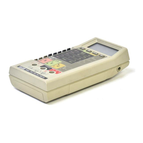
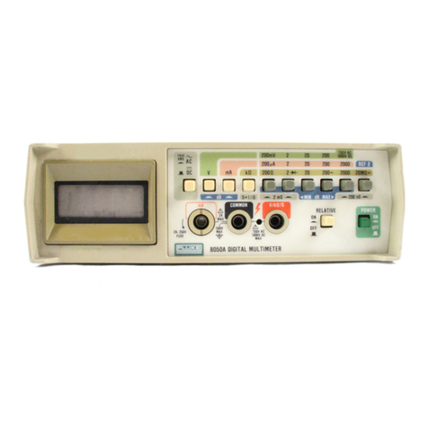
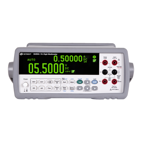
Fluke 8050A User manual

P/N 530907
October 1979 Rev 27/84
©1993 Fluke Cotporation. All rights reserved. Printed in U.S.A.
All product names are trademarks of their respective companies

Fluke Corporation (Fluke) warrants this instrument to be free from defects in material and workman-
ship under normal use and service for aperiod of 1year from date of shipment. Software is warranted
to operate in accordance with its programmed instructions on appropriate Fluke instruments, it is not
warranted to be error free. This warranty extends only to the original purchaser and shali not apply
to fuses, computer media, batteries or any instrument which, in Fluke’s sole opinion, has been subject
to misuse, alteration, abuse or abnormal conditions of operation or handling.
Fluke’s obligation under this warranty is limited to repair or replacement of an instrument which is
returned to an authorized service center within the warranty period and is determined, upon
examination by Fluke, to be defective, if Fluke determines that the defect or malfunction has been
caused by misuse, alteration, abuse, or abnormal conditions of operation or handling, Fluke will repair
the instrument and biii the purchaser for the reasonable cost of repair, if the instrument is not covered
by this warranty, Fluke will, if requested by purchaser, submit an estimate of the repair costs before
work is started.
To obtain repair service under this warranty purchaser must forward the instrument, (transportation
prepaid) and adescription of the malfunction to the nearest Fluke Service Center. The instrument shall
be repaired at the Service Center or at the factory, at Fluke’s option, and returned to purchaser,
transportation prepaid. The instrument should be shipped in the original packing carton or arigid
container padded with at least four inches of shock absorbing material. FLUKE ASSUMES NO RISK
FOR IN-TRANSIT DAMAGE.
THE FOREGOING WARRANTY IS PURCHASER’S SOLE AND EXCLUSIVE REMEDY AND IS IN
LIEU OFALL OTHER WARRANTIES. EXPRESSOR IMPLIED, INCLUDING BUT NOT LIMITEDTO
ANY IMPLIED WARRANTY OF MERCHANTABILITY, OR FITNESS FOR ANY PARTICULAR
PURPOSE OR USE. FLUKE SHALL NOT BE LIABLE FOR ANY SPECIAL, INDIRECT, INCIDEN-
TAL, OR CONSEQUENTIAL DAMAGES OR LOSS WHETHER IN CONTRACT, TORT. OR
OTHERWISE.
Immediately upon arrival, purchaser shali check the packing container against the enclosed packing
list and shall, within thirty (30) days of arrival, give Fluke notice of shortages or any nonconformity with
the terms of the order. If purchaser fails to give notice, the delivery shall be deemed to conform with
the terms of the order.
The purchaser assumes all risk of loss or damage to instruments upon delivery by Fluke to the carrier.
If an Instrument is damaged in transit, PURCHASER MUST FILE ALL CLAIMS FOR DAMAGE WITH
THE CARRIER to obtain compensation. Upon request by purchaser. Fluke will submit an estimate
of the cost to repair shipment damage.
Fluke will be happy to answer ail questions to enhance the use of this instrument. Please address your
requests or correspondence to: Fluke Corporation, P.O. Box 9090, Everett, WA 98206-9090, Attn:
Sales Department. For European Customers: Fiuke Europe B.V., P.O. Box 1186, 5602 B.D.,
Eindhoven, The Netherlands.
9/93
CHANGS/ERRATA INFORMATION
ISSUE NO: S5/93
This change/errata contains information necessary to ensure the accuracy of
the following manual. Enter the corrections in the manual if either one of
the following conditions exist:
1. The revision letter stamped on the indicated PCS is equal to or
higher than that given with each change
.
2. No revision letter is indicated at the beginning of the change/errata.
MANUAL
Title
:
Print Date:
Rev.- Date:
8050A
October 1979
2-7/84
C/E PAGE EFFECTIVITY
Page No. Print Date
1
2
3
7/85
9/88
5/93

8050A
1-
1, paragraph 1-2, change the following sentence,
oConductance measurements up to 100,000 M
oConductance measurements up to 100,000 Mequivalent resi
2-
6, Figure 2-4, change item 5,
PLACE 8050A mSERIES
PLACE 8050A IN SERIES
2-12, change paragraphs 2-43 and 2-44 to read:
Voltage Measurement
The following paragraphs contain additional information on
measurement techniques for voltage measurements.
On page 2-13, paragraph 2-54, change the second sentence,
FROM: This error is called the burden voltage.
TO: This voltage is called the burden voltage.
ERRATA #2
On page 2-3, following paragraph 2-21, add the following note:
NOTE
Asoftware error has been documented in the analog
to digital converter display sequence of the
proprietary integrated circuit, U17 .In all
ranges and functions, except negative dc volts and
conductance, three exact counts (347 1/2, 247 1/2,
and 147 1/2) cause the most significant digit to
occasionally display the next lower digit. One
condition, acount of exactly 47 1/2 causes the
display to occasionally indicate ail zeros. This
anomaly does not affect the function or accuracy
of the instrument.
ERRATA #1
On page
FROM:
TO:
On page
FROM:
TO:
On page
2-43.
2-44 .
stance
.
the
7/85 -1

8050A
ERRATA #3
On pages 5-8 and 601-8, Table 5-2 and 601-3, change R3,
FROM: R31 RES, MTL. FILM, 1000 +5%, 1/10W| 5142651 89536] 514265] 1
TO: R3 ]RES, MTL. FILM, 1000 +.05%, 1/lOW] 514265] 89536] 5142651 1
On page 5-9, Table 5-2, add the static sensitive symbol to U18, U19, and
U20 .
On page 601-9, Table 601-3, add the following:
U17^! IC, C-MOS, SI, N-CHANNEL, 40 PIN DIP] 524900] 89536] 524900] 1| 1
Ul8*i IC, SELECTED {8050A-450 6)I5159991 89536] 5159991 1] 1
U19*i IC, SELECTED (8050A-4506-Q1) I516005] 89536] 516005] 2| 1
U20*l IC, SELECTED (8050A-4506-01) j5160051 89536] 516005] REF
ERRATA #4
On page 4-7, Table 4-5, change the DISPLAY READING FOR steps 2and 3,
FROM: -37 .28 to -38.28
TO; -37.63 to -37.93
CHANGE #1 -27416
On pages 5-3 and 601-3, Tables 5-1 and 601-2,
CHANGE: MP25ITEST LEAD W/PROBE (Y8132) |516666 I89536 I516666 ]1
TO: MP25ITEST LEAD (TL70) i642033 I89536 !642033 1
1
ERRATA #5
On page 1-4, Table 1-2, for both DC Current and AC Current, change the
BURDEN VOLTAGE specifications,
FROM: 0.3V max
0.9V max
TO; 0.3V typical
0.9V typical
ERRATA #6
On page 4-2, Table 4-1, add the following to the bottom of the table:
AC Calibrator AC Voltage 100 mV to lOOV John Fluke Model 5200A 20
Hz +/-.!%
On page 4-6, add the following information:
4-35a. Use the following procedure to verify proper operation of the
low frequency ac voltage measurement functions:
7/85 2

8050A
1. Connect the AC Calibrator to the 8050A as follows: HI to the V/K
/S input connector and LO to the COMMON input connector.
2. For each step in Table 4-4a, select the switch positions shown
and adjust the AC Calibrator to the required 8050A voltage input
level and frequency, then verify that the 8050A display is within
limits
.
3. This concludes the low ac linear voltage test. If desired,
proceed directly to the dB Voltage Test.
Table 4-4a. Low Frequency AC Linear Voltage Test
‘
UUT INPUT DISPLAY *
STEP RANGE LEVEL FREQUENCY READING
120b raV 100 mV 20 Hz 98.90 -101.10
22.0V 1.OV 20 Hz '.9890 -1.01 10
320V lOV 20 Hz 9. ago -10.110
200V lOOV 20 Hz 98.90 -101 .10
*Typically 2to 4digits of rattle with be observed.
On Table 4-4, change the the following in the DISPLAY READING,
Change step 12,
FROM: 985 to 1015 .TO: .0985 to .1015
CHANGE #2 -34461
On page 5-3, Table 5-1,
CHANGE: H2 iSCREW, PHP, 6-32X1/2 1320051 i89536 |32005112
TO: H21 SCREW, PHP, 6-32X1/2 !853770 i8953 6i853770 I2
ERRATA #7
On page 4-8, paragraph 4-51, step 1, change reference of MP20 to MP31.
On page 4-9, Figure 4-2,
CHANGE: MP20 CHANGE: MP21
TO: MP32 TO: MP31
On page 4-10, paragraph 4-53, step 1, change reference of MP21 to MP32.
5/93 -3

Table of Contents
SECTION TITLE
1INTRODUCTION AND SPECIFICATIONS 1-1
1-1. INTRODUCTION M
M. OPTIONS AND ACCES SORIES M
1-
5. SPECIFICATIONS M
2OPERATION 2-1
2-
1. INTRODUCTION 2-1
2-3. SETTING UP YOUR INSTRUMENT 2-1
2-4. Unpacking 2-1
2-8. AC Line Voltage Requirements 2-1
2-10. Fuse Replacement 2-1
2-13. FRONT PANEL FEATURES 2-2
2-15. Display 2-2
2-18. SIGNAL INPUT LIMITS 2-2
2-20. OPERATING TECHNIQUES 2-3
2-22. AC/ DC Voltage (V) 2-3
2-24. AC/ DC Current (mA) 2-3
2-26. Resistance (D) 2-7
2-28. Conductance (S =in) 2-7
2-30. Diode Test 2-7
2-32. Relative (RELATIVE) ','.'.'.'.2-1
2-36. Decibel (dB) 2-11
2-38. INITIAL CHECKOUT PROCEDURE !!!!!!.!!!! 2-12
241. APPLICATIONS 2-12
2-43. DC Voltage Measurement 2-12
2-51. Current Measurement 2-13
2-56. Resistance Measurement 2-13
2-62. Conductance Measurement 2-14
2-80. Relative Measurement 2-16
2-
84. AC Voltage and Current Measurement 2-16
3THEORY OF OPERATION 3-1
3-
1. INTRODUCTION 34
3-3. FUNCTIONAL DESCRIPTION 3-1
3-5. CIRCUIT DESCRIPTION 3-1
i(continued on page ii)

TABLE OF CONTENTS, continued
SECTION TITLE PAGE
3-7. A/D Converter 3-1
3-18. Microcomputer 3-2
3-20. Signal Conditioning 3-6
3-31. True-RMS Converter 3-8
3-38. Touch-Hold Circuit 3-8
3-40. Voltage Protection 3-8
3-43. Current Protection 3-8
4MAINTENANCE 4-1
4-1. INTRODUCTION 4-1
44. SERVICE INFORMATION 4-1
4-7. GENERAL INFORMATION 4-1
4-9. Interior Access 4-1
4-24. dB Reference Impedance Power-Up Setting 4-4
4-26. Cleaning 4-5
4-28. PERFORMANCE TESTS 4-5
4-30. Initial Procedures 4-5
4-32. Display Test 4-5
4-34. Linear Voltage Test *4-6
4-36. dB Voltage Test ^4-6
4-38. Current Test |4-7
4-40. Resistance and Conductance Tests 4-7
4-42. CALIBRATION ADJUSTMENTS ...i 4-8
4-44. DC Calibration \4-8
4-46. AC Calibration |4-8
4-48. Jumper Selection I4-8
4-
57. TROUBLESHOOTING i4-12
5LIST OF REPLACEABLE PARTS 5-1
TABLE OF CONTENTS 5-1
5-
1. INTRODUCTION 5-2
5-3. PARTS ORDERING INFORMATION 5-2
6OPTIONS AND ACCESSORIES 6-1
TABLE OF CONTENTS 6-1
INTRODUCTION 6-2
ACCESSORIES 600-1
OPTIONS 601-1
7SCHEMATIC DIAGRAMS 7-1
TABLE OF CONTENTS 7-1

TABLE TITLE
I-l. 8050A Accessories ]_2
1-
2. 8050A Specifications 1-2
2-
1. 8050A Controls, Indicators, and Connectors 2-3
2-
2. Maximum Input Signal Limits 2-5
3-
1. AC Buffer Gains 3-8
4-
1. Required Test Equipment 4-2
4-2. dB Impedance Selection 4-4
4-3. Display Test 4-5
44. Linear Voltage Test 4-6
4-5. dB Voltage Test 4-7
4-6. Current Test 4_7
4-7. Resistance and Conductance Tests 4-8
4-8. DC Calibration 4. 10
4-9. AC Calibration 4-10
4-10. U5 Jumper Positions 4-11
4-II. U33 Jumper Positions 4-12
4-12. Test Points 4_I3
4-13. Troubleshooting Guide 4_14


Figures
FIGURE TITLE PAGE
Frontispiece 8050A Digital Multimeter vi
1-
1. 8050A Dimensions 1_5
2-
1. Controls, Indicators, and Connectors 2-2
2-2. Liquid Crystal Display 2-4
2-3. AC/ DC Voltage Operation 2-5
2-4. AC/ DC Current Operation 2-6
2-5. Resistance Operation 2-7
2-6. Conductance Operation 2-8
2-7. Diode Test Operation 2-9
2-8. Relative Operation 2-10
2-9. dB Voltage Operation 2-11
2-10. Circuit Loading Error 2-13
2-11. Calculating Burden Voltage Error 2-14
2-12. Transistor Beta Test Fixture 2-15
2-13. dB Circuit Gain or Loss Measurements 2-17
2-14. Waveform Comparisons 2-18
2-15. Crest Factor 2-19
2-16. Total RMS Value 2-19
2-
17. Measuring Amplifier Bandwidth 2-20
3-
1. 8050A Functional Block Diagram 3-3
3-2. A/D Converter 3_4
3-3. A/D Converter Waveforms 3_5
3-4. Microcomputer Simplified Block Diagram 3-6
3-5. Signal Conditioning 3_7
3-
6. RMS Converter 3-9
4-
1. Display PCB Access 4_3
4-2. Calibration Adjustment Locations 4-9
V

•lU

roduction and Specifications
1-1. iNTRODUCTION
1-2. Your John Fluke Model 8050A is aportable bench-
type digital multimeter (DMM) with a4-1 /2 digit liquid
crystal display (LCD). The 8050A has all the following
industry-standard features:
»Voltage measurements from 10 /uV to lOOOV dcand
10 mV to 750V true-rms ac.
®Current measurements from 10 nA to 2Adc and 10
/nA to 2A true-rms ac.
•Resistance measurements from 10 mfl to 20Mfl.
The 8050A also has several special measurement features.
These special features include the following;
•Conductance measurements up to 100,000 Mfl.
•Voltage measurements in decibels, that can be
referenced to 1of 16 user selected reference
impedances.
•Resistance ranges that supply enough voltage to
turn on aPN junction to allow diodes and
transistors to be tested.
•The ability to store any input signal as an offset or
relative reference value.
•Automatic polarity indication and overrange
indication.
®Protection from overloads and protection from
transients of up to 6kV, 10 microseconds.
®Dual-slope integration a/d conversion to ensure
noise-free measurements.
»Long term calibration stability (1 year).
1-3. The 8050A is warranted for a period of one year
upon shipment of the instrument to the original
purchaser. Conditions of the warranty are given at the
front of this manual. The 8050Ais typically powered from
ac line voltages but may be powered by the optional
rechargeable battery.
1-4. OPTIONS and ACCESSORIES
1-5. The use of the 8050A can be enhanced by the
accessories available for this instrument. The accessories
are listed in Table 1-1. This instrument can be ordered
with the Option 8050A-01 Rechargeable Battery.
Detailed information on options and accessories is
contained in Section 6of this manual.
1-6. SPECIFICATIONS
1-7. Specifications for the 8050A are listed in Table 1-2.
Specifications for the Option 8050A-01 Rechargeable
Battery and other accessory specifications are given in
Section 6 of this manual.

Table 1-1. 8050A Accessories
MODEL DESCRIPTION DESCRIPTION
C86 Ruggedized Carrying Case 80J-10 Current Shunt
Y8205 Soft Carrying Case 80K-6 High Voltage Probe
MOO-200-611 Offset Mounting Kit 80K-40 High Voltage Probe
MOO-200-612 Center Mounting Kit 83-RF RF Probe
MOO-200-613 Dual Mounting Kit 85-RF RF Probe
80T-M Touch-Hold Probe Y8100 DC/AC Current Probe
80T-150C Temperature Probe, Celsius Y8101 AC Current Transformer
80T-150F Temperature Probe, Fahrenheit Y8134 Deluxe Test Lead Set (safety designed)
801-600 Current Transformer Y8140 Slim-Flex Test Leads
Table 1-2. 8050A Specifications
ELECTRICAL
Functions
the electrical specifications given apply for an operating tem-
perature of 18°C to 28°C (64.4° Fto 82.4° F), relative humidity up to
90%, and a1-year calibration cycle.
DC volts, AC volts (linear and dB), DC current, AC current,
resistance, diode test, conductance, relative.
DC Voltage
RANGE RESOLUTION ACCURACY for 1-Year
±200 mV 10/iV
±2V 100 mV
±20V 1mV ±(0.03% of reading +2 digits).
±200V lOmV
±1000V 100 mV
INPUT IMPEDANCE 10 MO in parallel with <100 pF, all ranges.
NORMAL MODE REJECTION RATIO ...>60 dB at 60 Hz or 50 Hz.
COMMON MODE REJECTION RATIO ...>90 dB at dc, 50 Hz or 60 Hz (1 kO unbalanced)
(>120 dB available on request)
COMMON MODE VOLTAGE (MAXIMUM) 500V dc or peak ac
RESPONSE TIME TO 1second maximum
RATED ACCURACY
MAXIMUM INPUT 1000V dc or peak ac continuous (less than 10 seconds duration on
both the 200 mV and 2V ranges).
’DC voltages can also be measured using the dB mode with .01 dB resolution between 5% of range and full range.

SPECIFICATIONS
AC Volts (True RMS Responding, AC Coupled)
VOLTAGE READOUT ACCURACY ±(% of reading +number of digits), between 5% of range and fuii
range.
INPUT
VOLTAGE RESOLUTION RANGE 20 Hz** 45 Hz 1kHz 10 kHz 20 kHz 50 kHz
10 mV -200 mV 10juV 200 mV I
0.1V- 2V 100 pV 2V 1%+10 .5%+ 10 1%+10 5%- 30
1V-20V 1mV 20V
10V- 200V 10 mV 200V
100V -750V 100 mV 750V INOT SPECIF
**Typically 3to 5digits of rattle will be observed at full scale at 20 Hz.
RESOLUTION 0.01 dB from 5% of scale to full scale; 0.1 dBfrom1-5%ofsca!e,1 dB
below 1% of scale
VOLT -Hz PRODUCT 10^ max (200V max @50 kHz)
EXTENDED dB SENSITIVITY Typically -72 dB (6000 Ref) ±1 dB to 10 kHz
EXTENDED FREQUENCY RESPONSE ..Typically -3 dB at 200 kHz
COMMON MODE REJECTION >60 dB at 50 Hz or 60 Hz
RATIO (1 kO unbalance)
CREST FACTOR RANGE Waveforms with aPeak/RMS ratio of 1:1 to 3:1 at full scale,
increasing down range
INPUT IMPEDANCE 10 MQ in parallel with <100 pF
MAXIMUM INPUT VOLTAGE 750V rms or 1000V peak continuous (less than 10 seconds duration
on both the 200 mV and 2V ranges), not to exceed the volt-hertz
product of 10'^
RESPONSE TIME 2seconds maximum within arange
REFERENCE IMPEDANCES Sixteen user-selectable impedance reference levels are provided to
reference a0dBm. 1mW level (50n. 75Q, 930, 110n, 1250, 1350,
1500, 2500, 3000, 5000, 6000, 8000, 9000, 10000, 12000), and an
80 impedance reference level is provided to reference aOdBW level.
NOTE: On request, the NOT SPECIFIED portion of the 100V-750V Range can be extended
to the Volt-Hertz product of 10?
dB Ranges
INPUT
VOLTAGE dBm
(600^7 REF) ACCURACY: from 5% of range to full scale, 1-year
RANGE 20 Hz 45 Hz 1kHz 10 kHz 20 kHz 50 kHz
0.77 mV -2 mV
2mV -2V
0.1V- 2V
IV -20V
10V- 200V
100V -750V
-60 to -52
-52 to +8
-18 to +8
+2 to +28
+22 to +48
+42 to +60
200 mV*
200 mV*
2V
20V
200V
750V
0.5 dBm
±0.25 dBm ±0.15 dBm
1
i
±0.25 dBm ±0.75 dBm
*When 200 mVrange is selected the 8050A autoranges for best accuracy for 2V inputs and less.

RANGE RESOLUTION
200 mA 0.01 juA
2mA 0.1 pA
20 mA 1/jA
200 mA TOmA
2000 mA 100 mA
RESOLUTION |ACCURACY for 1- Year IBURDEN VOLTAGE
,±{0.3% of reading +2digits 0.3V max
20 mA 1/jA
200 mA TO ^A
2000 mA 100;UA 0.9V max
OVERLOAD PROTECTION (ac/dc) 2A/250V fuse in series with 3A/600V fuse {for high energy sources)
AC Current (True RMS Responding, AC Coupled)
RESOLUTION RANGE 20 Hz*" 45 Hz 2kHz 10 kHz 20 kHz BURDEN
VOLTAGE
10mA-200juA 0.01 M
100 -2mA 0.1 juA
1mA -20 mA 1juA
10 mA -200 mA 10 MA
100 mA -2000 mA lOOjuA
20 mA 2%+10
200 mA
2000 mA
2%+10 0.3V rms max
0.9V rms max
**Typically 3to 5digits of rattle will be observed at full scale at 20 Hz.
CREST FACTOR RANGE Waveforms with aPeak/RMS ratio of 1:1 to 3:1 at fuit scale
Resistance
RANGE RESOLUTION ACCURACY for 1-Year FULL SCALE VOLTAGE ACROSS
UNKNOWN RESISTANCE
20052 0.0152 .19V
2ka 0.152 1.2V
20 kS2 152 .2V
200 ka 1052 2V
2000 ka ±{0.25% reading +3digits) -2V
20 M52 11k52 12V
OVERLOAD PROTECTION 500V dc/ac rms on all ranges
OPEN CIRCUIT VOLTAGE Less than 3.5V on all ranges
RESPONSE TIME 10 seconds maximum on 20 MO range; 2seconds maximum on all
(TO RATED ACCURACY) other ranges
DIODE TEST These three ranges haveenough voltage to turn on silicon junctions
-H- to check for proper forward-to-back resistance. The 2kO range is
preferred and is marked with alarger diode symbol on the front
panel ofthe instrument. The three non-diode test ranges will not turn
on silicon junctions so in-circuit resistance measurements can be
made with these three ranges

Conductance
RANGE RESOLUTION ACCURACY for 1-Year
2mS
200 nS
.1 mS (10 MD.)
.01 nS
(100.000 Mn)
±(0.1% of reading +5digits)
±(0.5% of reading +20 digits)
MAXIMUM OPEN CIRCUIT VOLTAGE ..<3.5V
OVERLOAD PROTECTION 500V dc/ac rms on all ranges
CONDUCTANCE UNITS We use the international unit of conductance, thesiemen =S=1/Q.
Another unit of conductance is the mho
Relative
RELATIVE REFERENCE An input applied when the RELATIVE button is depressed totheON
position is held as “0” reference point. Subsequent readings indicate
the deviation (±) from this point. {Note: REL annunciator indicates
when this mode is enabled)
RELATIVE ACCURACY Error will not exceed the sum of the errors of the two measurements
ENVIRONMENTAL
Temperature Coefficient <0.1 times the applicable accuracy specification per ®C for 0®C to
18“C and 28®C to 50®C (32®F to 64.4®F and 82.4®F to 122®F)
Operating Temperature 0®C to 50®C (32®F to 122®F)
Storage Temperature (without batteries): -40®C to +70®C (-40®F to +158®F)
(with batteries): -40®C to +50®C (-40®F to +122“F)
Relative Humidity Up to 90%, 0®C to 35®C (32-95®F), up to 70%, 35®C to 50®C (95-
122° F), except on 2000 kO. 20 MQ, and 200 nS ranges where it is up
to 80%, 0°C to 35°C (32-95°F)
GENERAL
Maximum Common Mode Voltage 500V dc, or peak ac (low terminal potential with respectto power line
ground
Size 22 cm X6cm X25 cm (8V2in xIVi x10 in) see Figure 1-1
Weight 1.08 kg (2 lb 6oz)
Power Requirements (Line Only Models)
LINE VOLTAGE 90 to 110V ac 47 to 440 Hz
105 to 132V ac, 47 to 440 Hz
200 to 264V ac, 47 to 440 Hz
Factory configured for customer specified voltage
POWER CONSUMPTION 4W max
EC 348 Protection Class 1

INTRODUCTION
SPECIFICATIONS
1-6

2-1. INTRODUCTION
2-2. This section describes how to set up and make
measurements with your 8050A. Even though you may
have used amultimeter before, we recommend that you
read the entire section carefully so that you can use all of
the 8050A features.
2-3. SETTING UP YOUR INSTRUMENT
2-4. Unpacking
2-5. This instrument is shipped in aspecial protective
container that should prevent damage to the 8050A
during shipping. Check the shipping order against the
contents of the container and report any damage or short
shipment to the place of purchase or the nearest Fluke
Technical Service Center. Alist of these service centers is
located in Section 5. The container should include the
following:
•The 8050A Multimeter
•Two test leads (one red and one black)
«Line power cord
•The 8050A Instruction Manual
2-6. If reshipment of the instrument is necessary, please
use the original shipping container. If the original
container is not available, be sure that adequate
protection is provided to prevent damage during
shipment. We recommend that the instrument be
surrounded by at least three inches of shock-absorbing
material on all sides of the container.
2-7. Remove the 8050A from the container and place it
in aconvenient location. To facilitate operation in
different locations, the carrying handle on the meter can
be used as aprop-stand or positioned out of the way. To
position the handle, pull outward on the hubs of the
handle and rotate the handle into position.
2-9. AC line voltage requirements for your 8050A are
listed on adecal attached to the bottom of the instrument.
Refer to Section 4for the procedure to change the ac line
voltage setting.
CAUTION
Do not connect the power cable to the
Instrument before verifying that the intended
source matches the ac line configuration of
the Instrument.
2-10. Fuse Replacement
2-11. There is one, user replaceable, fuse in the 8050A.
The fuse, FI, and the fuse holder form an integral part of
the mA input connector and can be removed without
special tools. The fuse rating is: 2A, normal blow
(recommended part AGX2).
2-12. Use the following procedure to replace the fuse,
FI:
!. Set the POWER switch to OFF.
2. Remove the input power cord from the 8050A.

3. Refer to Figure 2-1, item 5for the location of
the fuse holder. The fuse holder is an integral
part of the mA input connector.
4. Using acoin or wide blade screwdriver, push in
while turning the fuse holder in the direction of
the arrow on the front panel decal.
5. Puli out the fuse holder and replace the
defective fuse.
2-13. FRONT PANEL FEATURES
2-14. Before using your multimeter, take afew minutes
to become familiar with the use of the controls,
indicators, and connectors of the 8050A. The front panel
features are shown in Figure 2-1 and described in Table 2-
1. The features of the Liquid Crystal Display (LCD) are
also described in the following paragraph.
2-15. Display
2-16. The features of the Liquid Crystal Display (LCD)
are shown in detail in Figure 2-2. The position of the
floating decimal point is determined by the range selected
(for linear measurements). The maximum measurement
value that can be displayed is one count less than the
range selected (e.g., maximum measured voltage that can
be displayed in the 200 mV range would be 199.99 mV).
2-17. To extend the life of the LCD and to ensure that
the display will be ready to operate, observe the following
precautions:
®Do not store or use the instrument in temperatures
above or below those specified in Section 1.
#Do not store or use the instrument in humidity
above that specified in Section 1.
NOTE
Low temperatures (within the specified
operating limits) will cause the LCD response
to be sluggish.
*Avoid prolonged exposure of the LCD to direct
sunlight (ultraviolet).
2-18. SIGNAL INPUT LIMITS
CAUTION
Exceeding the maximum signal Input limits
can damage the instrument.
Other manuals for 8050A
3
Table of contents
Other Fluke Multimeter manuals

Fluke
Fluke 1630 Instruction manual

Fluke
Fluke 79 III Use and care manual

Fluke
Fluke 867B User manual

Fluke
Fluke 117 User manual

Fluke
Fluke 28 II Ex Use and care manual

Fluke
Fluke 116 User manual

Fluke
Fluke 113 Use and care manual

Fluke
Fluke 106 User manual

Fluke
Fluke 1587 Use and care manual

Fluke
Fluke Digital Multimeter Use and care manual

Fluke
Fluke 8508A User manual

Fluke
Fluke 1550B User manual

Fluke
Fluke 1587 FC User manual

Fluke
Fluke CNX C3000 User manual

Fluke
Fluke 287 Use and care manual

Fluke
Fluke 77 Series III User manual

Fluke
Fluke 116 User manual

Fluke
Fluke ProcessMeter 787 User manual

Fluke
Fluke 179 User manual

Fluke
Fluke 91 Series II User manual