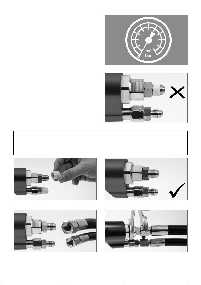
Oasis N-CNG P30 User manual

OASIS ENGINEERING LIMITED · 129 Birch Avenue, Tauranga, New Zealand
Tel. +64 07 928 38 08 · Email: info@oasisngv.com
N-CNG P30 / P36
CSA/ANSI NGV 1-2017 + ISO 14469:2017
CNG NOZZLE
INSTALLATION AND OPERATING MANUAL
22 . 2022

Please read this manual carefully before installation or operation of the nozzle.
Be sure all instructions are understood. Correct installation, use and maintenance are essential. In
case of doubt or question, please contact your service contractor or the manufacturer.
DESCRIPTION
The N-CNG nozzle is designed for CNG refuelling of vehicles equipped with receptacles to NGV1 or
ISO 14469.
The nozzle either comes with a Service Pressure rating B200 /P30 = 207 bar/3000 psi ( EU Standard)
or B250 / P36 = 250 bar / 3600 psi ( US Standard ).
The pressure rating is marked on the nozzle connector and can also be identified by the pressure color
code ring: blue = B200 / P30 ( EU Standard ) and yellow = B250 /P36 ( US Standard ). The N-CNG is a
so-called 'Type 1' nozzle and is used by pulling the lever. It also integrates an automatic venting and
swivel function, suitable for public and private CNG refuelling stations. The nozzle is designed to only
allow gas to flow when it is correctly coupled and to not allow uncoupling from the vehicle refuelling
receptacle when the nozzle is pressurised.
APPROVALS / OPERATING CONDITIONS
The N-CNG nozzle is designed and tested to CSA/ANSI NGV 1-2017 and ISO 14469:2017 for the use
of CNG refuelling of Natural Gas Vehicles with B200 / P30 and B250 / P36 receptacles.
Each nozzle is factory tested and labeled with the prescribed marking.
Media compatibility CNG, Natural Gas, Methane, Biogas
Cv 1.1
Service pressure B200 / P30 ( 207 bar / 3000 psi ) or
B250 / P36 ( 250 bar / 3600 psi )
Working pressure ( max. ) 312,5 bar
Test Pressure 375 bar
Weight 1,6 kg
Media temperature range -40° C ( -40° F ) to 65° C (149° F )
Ambient temperature -40° C ( -40° F ) to 85° C ( 185° F )
Connection to hose Swivel connection to fill line ( FL ): 9/16"-18 JIC 37° //
9/16"-18 SAE ( with / without adapter)
Swivel connection to vent line (VL ): 7/16"-20 JIC 37° //
7/16"-20 SAE ( with / without adapter)
Dimensions ( max. ) Width: 63 mm
Length: 356 mm
Height: 133 mm
2
DRAFT

GENERAL INFORMATION ABOUT CNG / WARNINGS
• CNG is compressed natural gas that is transported and stored under high pressure. It is lighter
than air. Commercial CNG is odorised to enable detection by its sulfurous smell. Small leakages
typically cannot be seen and merely detected by its smell. When exposed to the atmosphere It
has an expanding factor proportional to the Service Pressure, e.g. 1:207 at a Service Pressure of
207 bar: one liter of compressed gas corresponds to 207 liter of flammable gas.
High pressure gas and gas equipment can cause serious harm to both infrastructure and
personnel if safety precautions are not followed
A small gas release upon uncoupling is normal – but uncontrolled gas release to the
atmosphere must be avoided. If you suspect a leakage: stop refuelling immediately, use
the emergency button to shut off the dispenser, immediately evacuate the area and inform
station personnel.
• CNG/Natural Gas is extremely flammable:
Open fires, smoking, sources of static electricity and the use of mobile phones or other
electric devices is prohibited in the area of gas transfer. Turn off vehicle engine before
refuelling.
• Failure or improper use of this product can cause death, personal injury and property
damage.
CNG is extremely cold when released to the air (depressurised).
INSTALLATION
High pressure gas and gas equipment can cause serious harm to both infrastructure and personnel
if safety precautions are not followed.
Oasis recommends the use of personal protective equipment ( PPE ) when working with high pres-
sured gases ( CNG ) in accordance to the relevant health and safety regulations:
Foot Protection Hearing Protection Safety Helmets Hand Protection Safety Glasses
3
DRAFT

Ensure the system is free of dirt and foreign matter,
vented and isolated before any installation or
servicing work is carried out.
The N-CNG is delivered ready for use. This
installation must only be done by an authorised
service engineer who is trained to ensure com-
pliance with all relevant national regulatory
conditions. The nozzle is designed for the con-
nections as mentioned in 'Approvals / Operating
conditions' and must not be used with any NPT
or other thread sealing adapters. The designated
connections do not require thread sealants.
Therefore, do not use PTFE sealing tape or
liquid seal for any sealing as electrical conducti-
vity may be insufficient and particles of the tape
commonly become loose and could clog the
nozzle valve or damage vehicle motor parts.
This device complies with CSA/ANSI NGV 1-2017
and ISO 14469:2017. The installation of this
device shall conform to the requirements of the
authorities having jurisdiction or, in the ab-
sence of requirements, to NFPA 52 Standards,
Compressed Natural Gas (CNG) Vehicular Fuel
Systems, or CAN/CSA-B108, NGV Fuelling
Stations Installation Code, as applicable.
Needed tools:
2 x Spanner with width of 23 mm / 7/8"
2 x Spanner with width of 17 mm / 11/16"
1 x Spanner with width of 14 mm / 9/16"
1 x Foaming agents or spray bottle with snoop or soapy water
Check if connections correspond in type and
size, e.g. JIC 37° 9/16-18" male / female
Remove caps from nozzle.
Connect the hoses to the nozzle. Torque the fill line
to 45 Nm and torque the vent line to 35 Nm or as
per hose fitting suppliers recommended tightening
torque.
Do not use pliers.
Check sealing surfaces of connections at the
nozzle as well as the hose assemblies.
4
DRAFT

After connecting to the hose assembly, an ope-
rational test shall be performed. It is essential to
examine that the nozzle, hose connector and
swivel are tight under pressure and do not leak
– e.g. by external application of foaming agents.
NOTE : Pressurise system gradually while
checking for leaks.
Always put back the nozzle into the nozzle
holder.
ATTENTION: Do not drop.
Do not leave on the floor
TROUBLESHOOTING
• If the lever cannot be pulled back
Check the correct seating of the nozzle to the vehicle coupling. Make sure you push the
nozzle straight and aligned towards the receptacle. A safety feature prevents operation of the
nozzle if the connection is misaligned. If you have any doubts or questions, please contact the
station personnel.
Never force operation of the nozzle. If the connection process does not work smoothly,
disconnect and re-connect nozzle as indicated under 'Operation Instructions'.
• Leakage ( escaping gas )
A small gas release upon uncoupling is normal. If uncontrolled and / or permanent gas
release to the atmosphere occurs, immediately stop fuelling. If the leakage continues, push
emergency button of dispenser, leave area and inform station personnel.
If area is safe, check tight connection between vehicle connection and the N-CNG nozzle.
Check seals of vehicle connection and the N-CNG. If the problem persists, notify the station
personnel or the service contractor.
• If the latching does not work:
Disconnect and re-connect nozzle as indicated under 'Operation Instructions'.
If it continues to not work properly or you have any doubts or questions, please contact the
station personnel.
• If the nozzle cannot be disconnected after refuelling:
Connect nozzle once again as indicated under chapter 'Operation Instructions'. Then try to
disconnect and take off the N-CNG.
Never force operation of the nozzle. If the disconnection process does not work smoothly,
inform station personnel.
If self-service is not possible, please contact a service company specialised and certified in
CNG Service Station installations.
5
DRAFT

OPERATING INSTRUCTIONS
Please follow any additional
or deviating operating
instructions displayed
at the dispenser.
Ensure that all coupling parts,
seals and sealing surfaces of
nozzle and vehicle filling point
are clean and undamaged.
Turn o vehicle engine.
Take nozzle from dispenser.
Align nozzle with vehicle
sided fill point as shown.
Remove nozzle and put back in
dispenser nozzle holder.
Push nozzle firmly onto the vehicle
filling point.
OFF
On completion of refuelling,
squeeze and release lever.
Latch will automatically release.
Fuelling should start automati-
cally OR has to be activated at
the dispenser. Please follow
operating instructions displayed
at the dispenser.
Hold the lever pulled and lock
the hold-open latch as shown
to open the nozzle valve.
Release the lever and it will stay
in the open position.
Do not lean on / tilt the nozzle.
In that position, pull the lever.
If the nozzle is correctly coupled
,
a green indicator ring appears
on the coupling part.
Do not drop.
Do not leave on
the floor.
Always put back
in nozzle holder.
6
DRAFT

FILL POINT ADAPTERS
The use of fill point adapters is strictly prohibited.
MAINTENANCE
The N-CNG nozzle is a mechanical device that may become inoperative due to wear, corrosion and
ageing of components. Regular inspections and maintenance are essential for a safe operation.
Daily visual inspections of the nozzle by trained personnel should be carried out to ensure proper
function. The nozzle coupling shall be clean and not show any signs of damage (e.g. dents, sharp
edges, blocked lever, swivel non-rotating). Especially check the inner area of the front coupling part
of the nozzle to confirm there is no dirt or mechanical damage. If there are issues with latching, it is
an indication that the gating latch must be replaced. If the operation of the nozzle handle is excessively
tight, or requires more force to actuate than normal after a period of use, a trained personnel is
required to re-lubricate the nozzle with grease as per the servicing instructions.
The nozzle condition shall be thoroughly checked during the annual pump maintenance by competent
personnel. Applicable laws, regulations and Codes of Practice have to be followed. Nozzles in unfit
condition for use must be immediately replaced. The nozzle should be inspected for damage or leaks
every 20,000 cycles or one year, whichever happens first. In case of an abnormality it should be
serviced by the manufacturers authorized service centre. In addition, it should be serviced by the
manufacturers authorized service centre after every 40,000 filling cycles as per ISO 14469:2017 or
every four years, which ever happens first.
CONDITIONS OF USE
Failure to comply with any warnings, instructions, procedures or any other common sense procedures
may result in injury, equipment damage, property damage or poor performance of the equipment.
Oasis accepts no liability for direct, indirect, incidental, special, or consequential damages resulting
from failure to follow any warnings, instructions and procedures in this manual, or any other common
sense procedures generally applicable to equipment of this type. The foregoing limitation extends to
damages to person or property caused by the unit or damages resulting from the inability to use the
unit including loss of profits, loss of products, loss of power supply, the cost of arranging an alternative
power supply, and loss of time, whether incurred by the user or their employees, the installer, the
commissioner, a service technician, or any third party. The manufacturer reserves the right to change
the specifications of its products or the information in this manual without necessarily notifying its users.
Variations in installation and operating conditions may affect the unit‘s performance. Oasis has no control
over each installation‘s unique operating environment. Hence, no representations or warranties concerning
the performance of the unit under the actual operating conditions prevailing at the installation are made.
A technical expert of your choosing should validate all operating parameters for each application.
Oasis has made every effort to explain all servicing procedures, warnings, and safety precautions as clearly
and completely as possible. However, due to the range of operating environments, it is not possible to
anticipate every issue that may arise. This manual is intended to provide general guidance. For specific
guidance and technical support, contact your authorized supplier or specialist service contractor.
Only approved original parts shall be used and no unauthorised modifications to the hardware shall
be made. The use of non-approved parts or modifications will void all warranties and approvals. The
use of non-approved parts or modifications may also constitute a safety hazard. Information in this
manual shall not be deemed a warranty, representation, or guarantee. For warranty provisions appli-
cable to this unit, please refer to the warranty provided by the supplier.
Every effort has been made to ensure the accuracy of this document. However, it may contain technical
inaccuracies or typographical errors. Oasis assumes no responsibility for and disclaims all liability of
such inaccuracies, errors or omissions in this.
7
DRAFT

WARRANTY
Oasis guarantees against defective materials and manufacturing for 12 months from date of supply.
If the delivery date cannot be established, the production date applies. This can be traced back by
the serial number on the CNG nozzle bodies.
Excluded are nozzles and parts subjected to wear and tear and damages caused by improper use,
for example the use with unsuitable media. Furthermore excluded are indirect damages and costs,
such as travelling related to exchange and repair work. We refuse any liability for consequential loss
or damage resulting from the use of our nozzle.
STOP FUELLING
START FUELLING
8
DRAFT
This manual suits for next models
1
Table of contents
Other Oasis Cables And Connectors manuals