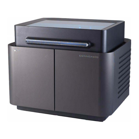
Objet Alaris30 User manual

Alaris303‐DPrinter
InstallationGuide
DOC‐04006
September2008
ObjetGeometriesLtd.


Alaris30 Installation Guide
Objet Confidential and Proprietary Information
3
Copyright
Copyright©2008byObjetGeometriesLtd.Allrightsreserved.
ThisdocumentationcontainsproprietaryinformationofObjetGeometriesLtd.This
informationissuppliedsolelytoassistauthorizedinstallersoftheAlaris303‐Dprinting
systems.Nopartofthisdocumentmaybeusedforotherpurposes,anditmaynotbe
disclosedtootherparties.
Thespecificationsonwhichthisdocumentisbasedaresubjecttochangewithoutnotice.
Nopartofthisbookmaybereproducedinanyformorbyanymeans,norstoredina
databaseorretrievalsystem,withoutpriorpermissioninwritingfromObjetGeometries
Ltd.
September2008
DOC‐04006Rev.A
Trademarks
ThefollowingareregisteredtrademarksofObjetGeometriesLtd.:Objet®,Fullcure®.
ThefollowingaretrademarksofObjetGeometriesLtd.:Alaris30,Connex500,Digital
Material,Eden,Eden500V,Eden350V,Eden350,Eden260,Eden250,PolyJet,PolyLog,Objet
Studio,JobManager,Tango,VeroBlue,VeroWhite,VeroBlack.
MicrosoftandMicrosoftXParetrademarksofMicrosoftCorporation.
Allnamesofproductsandservicescitedinthisbookaretrademarksorregistered
trademarksoftheirrespectivecompanies.
Using this Guide
Thisinstallationguideprovidesinstructionsfortheproperinstallation,placementand
testingoftheAlaris303‐Dprintingsystemuponarrivalatthecustomersite.

Alaris30 Installation Guide
Objet Confidential and Proprietary Information
4
Terms Used in This Guide
Alaris30 printer The Alaris30 3-D printers referred to in this guide.
model material Material used for building models.
support material Material used for supporting the structure of models during
production.
Alaris30 computer The computer built into the Alaris30 printer.
Alaris30 software Software running on the computer inside the Alaris30 printer, which
controls all printer operations.
Alaris30 printer
interface The GUI (graphical user interface) used for controlling the Alaris30
printer.
build tray In the Alaris30 printer: The surface upon which models are produced.

Alaris30 Installation Guide
Objet Confidential and Proprietary Information
5
Contents
1 Installation Checklist
2 Unpacking
2.1 RequiredToolsandParts ........................................................................ 8
2.2 ExternalInspection................................................................................... 8
2.3 UnpackingProcedure .............................................................................. 9
3 Axis Locks and Print-Head Cover
3.1 ReleaseX‐axis.......................................................................................... 12
3.2 RemovePrint‐HeadCover.................................................................... 13
4 Connect Cables and Test Voltage
4.1 InstalltheKVMSwitchbox ................................................................... 14
4.1.1 ConnectCables ........................................................................ 15
4.1.2 SwitchingbetweenComputers ............................................. 16
4.2 ConnectCommunicationCable ........................................................... 17
4.3 PreparePowerCable ............................................................................. 17
4.4 VisualCheckofCablesandCards....................................................... 18
5 Setup Server Workstation & Alaris30 Computer
5.1 TurnPowerOn ....................................................................................... 20
5.2 SetupPoint‐to‐PointCommunication................................................. 20
5.2.1 InformationfromServerWorkstation.................................. 20
5.2.2 Alaris30ComputerSetup....................................................... 22
5.2.3 ServerWorkstationSetup ...................................................... 27
5.2.4 DisableFirewall ....................................................................... 30
5.2.5 TestCommunication............................................................... 32
5.3 DisableAutomaticUpdatesforWindows.......................................... 34
5.4 DisablePowerSaver .............................................................................. 35
5.5 DisableAntivirusSoftware................................................................... 38

Alaris30 Installation Guide
Objet Confidential and Proprietary Information
6
5.6 SetupSharing.......................................................................................... 38
5.6.1 ServerWorkstationProcedure .............................................. 38
5.6.2 Alaris30ComputerProcedure............................................... 40
5.6.3 VerifySharingSetup............................................................... 42
5.7 InstallObjetStudioonServerWorkstation........................................ 42
5.8 BackUpAlaris30Folder........................................................................ 42
6 Material Installation & Calibration Tests
6.1 InstallModelandSupportMaterials................................................... 43
6.2 CalibrationTests..................................................................................... 43
6.3 ModelScaling.......................................................................................... 43

Alaris30 Installation Guide
Objet Confidential and Proprietary Information
7
1 Installation Checklist
Inspect the printer shipping carton to ensure that it is undamaged (page 8).
Open the carton and ensure that the printer and its cover are not damaged
(page 10).
Place the printer on the work surface (page 11). Ensure that there is
sufficient space around the printer (as specified in the Site Preparation
Guide).
Release the axis lock (page 12).
Remove the protective covers from the print heads (page 13).
Connect the KVM switch (page 14).
Connect the server workstation computer to the printer (page 17).
Configure a point-to-point connection from the Server workstation to the
printer (page 19).
Install Objet Studio with Job Manager on the Server workstation (page 42).
Backup the Alaris30 folder (page 42).
Install the model, support, and waste cartridges in the materials drawer
(page 43).
Perform all of the calibration procedures (page 43).
Send a model file (can be a customer model) to the printer and perform a
test printing (page 43).
Explain contents of Startup Kit to customer.
Install the water jet cleaning unit.
Fill out the Completion of Installation (COI) form.
Fill out the Installation Report form.
Fill out the Field Service Report (FSR) form.

Alaris30 Installation Guide
Objet Confidential and Proprietary Information
8
2 Unpacking
2.1 Required Tools and Parts
Thefollowingtoolsarerequiredforthischapter:
•Cuttingpliers
•Pliers
•Handpallettruck
2.2 External Inspection
Beforeremovingthecoverofthepackage,dothefollowing:
•Inspecttheoutsideoftheshippedpackagefordamage.
•Notethestatusofthetiltandshockdetectors.
Figure 2–1 Tilt and Shock Detection
Iftheoutsideofthepackageisdamagedorthetiltandshockdetectors
haveturnedred,thenthepackagewasnothandledproperlyduring
shipment.Inthiscasedothefollowing:
• Photographthedamageandthestatusofthetiltandshock
detectors.
•Contacttheshippersofthepackage.
•Emailyourregionalofficewithdetailsofthedamageandsticker
status.

Alaris30 Installation Guide
Objet Confidential and Proprietary Information
9
Onlyproceedwiththeunpackingandinstallationoftheprinter,ifthe
shipperandyourregionalofficeadvisesyoutoproceed.
2.3 Unpacking Procedure
1. Ensurethattheprinterisunpackedonalevelsurface.
2. Cutthebandsaroundthepackage(withcuttingpliers).
3. Openthetopcoverofthepackage.
Figure 2–2 Top Cover Open
4. Removethewoodencornersupports.
5. Liftupandremovethecoverinsidethepackage.
6. CheckthestatusoftheshockdetectoronthetopoftheAlaris30
printer.
Iftheshockdetectorhasturnedred,thenthepackagewasnot
handledproperlyduringshipment.Inthiscasedothefollowing:
•Photographanydamageandthestatusoftheshockdetectors.
•Contacttheshippersofthepackage.
•Emailyourregionalofficewithdetailsofanydamageandsticker
status.

Alaris30 Installation Guide
Objet Confidential and Proprietary Information
10
Onlyproceedwiththeunpackingandinstallationoftheprinter,if
theshipperandyourregionalofficeadvisesyoutoproceed.
7. Removethestaples(usepliers)connectingtheoutsidepackagingto
thepallet.LiftuptheoutsidepackagingstraightofftheAlaris30
printer.
8. RemovethepackingmaterialaroundtheAlaris30printer.
Figure 2–3 Alaris30 Printer Packing Material
9. Oncethepackingmaterialisremoved,examinetheAlaris30printer
fordamage.Givespecialattentiontoloosepartsorcables,totheUV
protectionglass,andtotheprintingheads.
Iftheprinterisdamaged,dothefollowing:
•Photographthedamage.
•Emailyourregionalofficewithdetailsofthedamage.
Ifthedamagetotheprinterwouldstoptheprinterfromworking
safelyorefficiently,stoptheinstallationandawaitfurther
instructionsfromtheregionaloffice.
The shock detector on the top of the Alaris30 printer acts as a second check on the
handling of the package.

Alaris30 Installation Guide
Objet Confidential and Proprietary Information
11
10. CarefullylifttheAlaris30printeroffthepalletusingahandpallet
truckandmovetheprintertoitsfinallocation.
Objet recommends that the customer keep and store the pallet, the outside
packaging and the packing material for possible future use.

Alaris30 Installation Guide
Objet Confidential and Proprietary Information
12
3 Axis Locks and Print-Head Cover
Thefollowingtoolisrequiredforthischapter:
•Cuttingpliers.
3.1 Release X-axis
CutandremovethecabletiesattachedtotheX‐axisbeltandprinthead.
Figure 3–1 X-axis Cable Ties
Caution: Perform these sections with the printer off.

Alaris30 Installation Guide
Objet Confidential and Proprietary Information
13
3.2 Remove Print-Head Cover
Onceallthecabletiesarecut,removetheheads‐protectingcover(shown
inFigure3–2)bydoingthefollowing:
• Opentheheads‐protectingcover.
•Pullthecoverfromthebottomsidewaysofftheprinthead.
Becarefulanduseextracautiontomakesurethattheprintingheadsand
therollerarenotdamagedwhileremovingthecover.
Figure 3–2 Head Protection Cover

Alaris30 Installation Guide
Objet Confidential and Proprietary Information
14
4 Connect Cables and Test Voltage
4.1 Install the KVM Switchbox
TheinstallationkitincludesaKVMSwitchunit.TheKVMSwitchallows
youtocontrolthetwocomputers(theAlaris30computerandtheServer
workstation)withonekeyboard,monitorandmouse.TheKVMSwitch
supportsUSBinputdevices(keyboardandmouse),VGAandSVGA
video;andcomputerswithUSBports.
Important ThemouseandkeyboardmustbeUSBdevices.PS2‐to‐USBconversion
plugsarenotsupported.
TheKVMswitchcomeswithcablesforconnectingcomputerstothe
switch.Oneendofthecable,whichisconnectedtotheKVMswitch,
consistsofaD‐typeconnectorandanaudioconnector.Theotherendof
thecablehasamonitorconnector,aUSBconnectorandaudioconnectors.
Avoidhavingcablesnearair‐conditioningequipment,ormachinesthat
createelectricalnoise.
Simplekeyboardcommands(knownasHotkeys)controlwhichcomputer
iscurrentlyconnectedtothekeyboardandmouseandhasitsoutput
displayedonthemonitor.
A 101/102-key USB keyboard or similar is recommended.
During the installation of the KVM switch, the audio connectors are not used.
To ensure proper operation of the KVM switch, the Server workstation and the
Alaris30 printer must be properly grounded.

Alaris30 Installation Guide
Objet Confidential and Proprietary Information
15
4.1.1 Connect Cables
1. EnsurethatthepowerisofftotheServerworkstationandtothe
Alaris30printer.
2. Plugthekeyboard,monitorandmousecablesintotheirrespective
portsontheKVMSwitch(seeFigure4–1).Thekeyboardandmouse
portsarelabeledwithiconstoindicatewhichportiswhich.
Figure 4–1 KVM Switch Connections Overview
3. ConnectthecablebetweentheKVMSwitchandtheServer
workstation.Thatis,connectthecable’sKVMSwitchD‐type
connectortotheD‐typesocketontheswitchandconnectthecable’s
monitorandUSBconnectorstotherelevantsocketsontheServer
workstation(seeFigure4–2).
If the Server workstation has the “Keyboard Power On” function, unplug the Server
workstation’s power cord.

Alaris30 Installation Guide
Objet Confidential and Proprietary Information
16
Figure 4–2 Connecting KVM Switch Cables to Server Workstation
4. ConnectthecablebetweentheKVMSwitchandtheAlaris30printer.
Thatis,connectthecable’sKVMSwitchD‐typeconnectortotheD‐
typesocketontheswitch,andconnectthecable’smonitorandthe
USBconnectorstotherelevantsocketsatthebackoftheprinter.
4.1.2 Switching between Computers
TheswitchesonthefrontoftheKVMcanbeusedtoswitchcontrol
betweentheServerworkstationandtheAlaris30computer.
Inadditionhotkeysexistfordoingtheswitchingfromthekeyboard.The
defaulthotkeyforswitchingbetweenthecomputersistheScrollLockkey
(onthekeyboard).PushtheScrollLockkeytwiceandthentheEnterkey
tochangethecontrollingcomputer.

Alaris30 Installation Guide
Objet Confidential and Proprietary Information
17
IftheScrollLockkeyisforsomereasonnotavailable,usethefollowing
proceduretochangethehotkeytotheCtrlkey(thatis,topushingtheCtrl
keytwiceandthentheEnterkey):
1. PressandholdtheNumLockkey.
2. WhiletheNumLockkeyisdown,pressandreleasetheminuskey.
3. ReleasetheNumLockkey.Iftheprocedurewasperformed
correctly,uptothisstep,theCapsLockandtheScrollLockLEDs
shouldflashalternatively.
4. PressandreleasetheTkey.
4.2 Connect Communication Cable
Connectthepoint‐to‐pointNetworkCrosscablefromthebackofthe
printertoavacantnetworkportontheServerworkstation.
4.3 Prepare Power Cable
Attach(orhavethecustomer’selectricalpersonnelattach)theappropriate
powerplugtothepowercablefromthebackoftheprinter.
The minus key must be released within half a second, otherwise the procedure
must be started again.
At this point, ordinary keyboard and mouse functions are suspended. They are
restored after the next step.
This procedure acts as a toggle between the two switching methods. To revert to
the Scroll Lock method, perform this procedure again.
Chapter 5, Setup Server Workstation & Alaris30 Computer contains the procedure
to set up the point-to-point communication between the Alaris30 computer and the
Server workstation. To avoid difficulties with this procedure, Objet recommends
thatthecustomerconnecttheServerworkstationtothe customer’sLANbefore the
Objet point-to-point cable is installed.

Alaris30 Installation Guide
Objet Confidential and Proprietary Information
18
4.4 Visual Check of Cables and Cards
Opentheprinterandvisuallycheckthatallthecardsandcablesareseated
properly.

Alaris30 Installation Guide
Objet Confidential and Proprietary Information
19
5 Setup Server Workstation &
Alaris30 Computer
Thischaptercontainsproceduresforthefollowing:
• Settingupandcheckingpoint‐to‐pointcommunicationbetweenthe
ServerworkstationandtheAlaris30computer(seepage20)
• DisablingsoftwareandWindowsoptionsontheServerworkstation:
•Automaticupdates(seepage34)
•PowerSaver(seepage35)
•Antivirus(seepage38)
•Firewall(seepage30)
• SettingupsharingbetweentheServerworkstationandtheAlaris30
computer(seepage38)
• PreparingfortheinstallationoftheObjetStudiosoftware(see
page42)
• BackinguptheAlaris30folderontheServerworkstation(see
page42)

Alaris30 Installation Guide
Objet Confidential and Proprietary Information
20
5.1 Turn Power On
TurnonthepowertotheServerworkstationandtheAlaris30printer.
ThefollowinginstructionsareforthefirstlogontotheAlaris30printer.
1. Press(atthesametime)Alt‐Ctrl‐Deletetwice.
2. LogintotheAlaris30printeras“administrator”.
5.2 Setup Point-to-Point Communication
5.2.1 Information from Server Workstation
1. OpentheStartmenuontheServerworkstation,right‐clickonMy
ComputerandselectPropertiesfromthedrop‐downmenu.The
SystemPropertieswindowopens.
Figure 5–1 System Properties Window
No password is required for the Alaris30 printer.
Other manuals for Alaris30
2
Table of contents
Other Objet 3D Printer manuals
Popular 3D Printer manuals by other brands

Inventorcloud
Inventorcloud Invent3D Assembly instructions

re:3D
re:3D TERABOT Getting started guide

RAISE 3D
RAISE 3D Pro3 Series user manual

2PrintBeta
2PrintBeta Beta Prusa V2 Deluxe Assembly instructions

3D Upfitters
3D Upfitters CR-10S Pro/CRX R1 Enclosure Kit instruction manual

CULTIVATE 3D
CULTIVATE 3D The Beast v2 Build manual