Objet Alaris30 User manual

Copyright © by Objet Geometries Ltd. all rights reserved.
Objet Confidential and Proprietary Information
DOC-04204 Rev. A
Alaris30
Service Guide
Maintenance
YearlyMaintenanceTasks.............................................................................................2
Z‐axisCoverCleaning...................................................................................................3
LeaksandSpills..............................................................................................................7
ModelCoolingFanInspection.....................................................................................9
HeadDriverInterfaceCardConnectorCleaning ...................................................11
ElectricalCableInspection..........................................................................................13
NeedleInspection&Replacement ............................................................................14
XEncoderReplacement ..............................................................................................78
SupportandModelMaterialFilters..........................................................................25
PumpTubing ................................................................................................................27
WiperAssemblyServicing .........................................................................................32
RollerAssemblyServicing..........................................................................................38
RollerReplacement......................................................................................................49
HeadDriverCardCoolingFanFilters......................................................................67
PrintHeadReplacement.............................................................................................69
XEncoderReplacement ..............................................................................................78
PrintBlockReplacement.............................................................................................88
MainPowerSupplyReplacement .............................................................................96
UVPowerSupplyReplacement...............................................................................102

Alaris30 Service Guide
DOC-04204 Rev. A Confidential and Proprietary Information 2
1 Yearly Maintenance Tasks
RefertotheAlaris30PreventiveMaintenanceKit(DOC‐04005)forthe
preventivemaintenancetasklistfortheAlaris30printers.
Alaris30 Service Guide
DOC-04204 Rev. A Confidential and Proprietary Information 3
2 Z-axis Cover Cleaning
Thez‐axiscovercollectsresiduethatfallsinsidetheprinter.Periodically,
emptythecovertopreventbuildupofforeignmatter.Thez‐axiscoveris
behindtheblower.
2.1 Tools
•Allenkeyset
2.2 Procedure
1. Removetherearpaneloftheprinter.
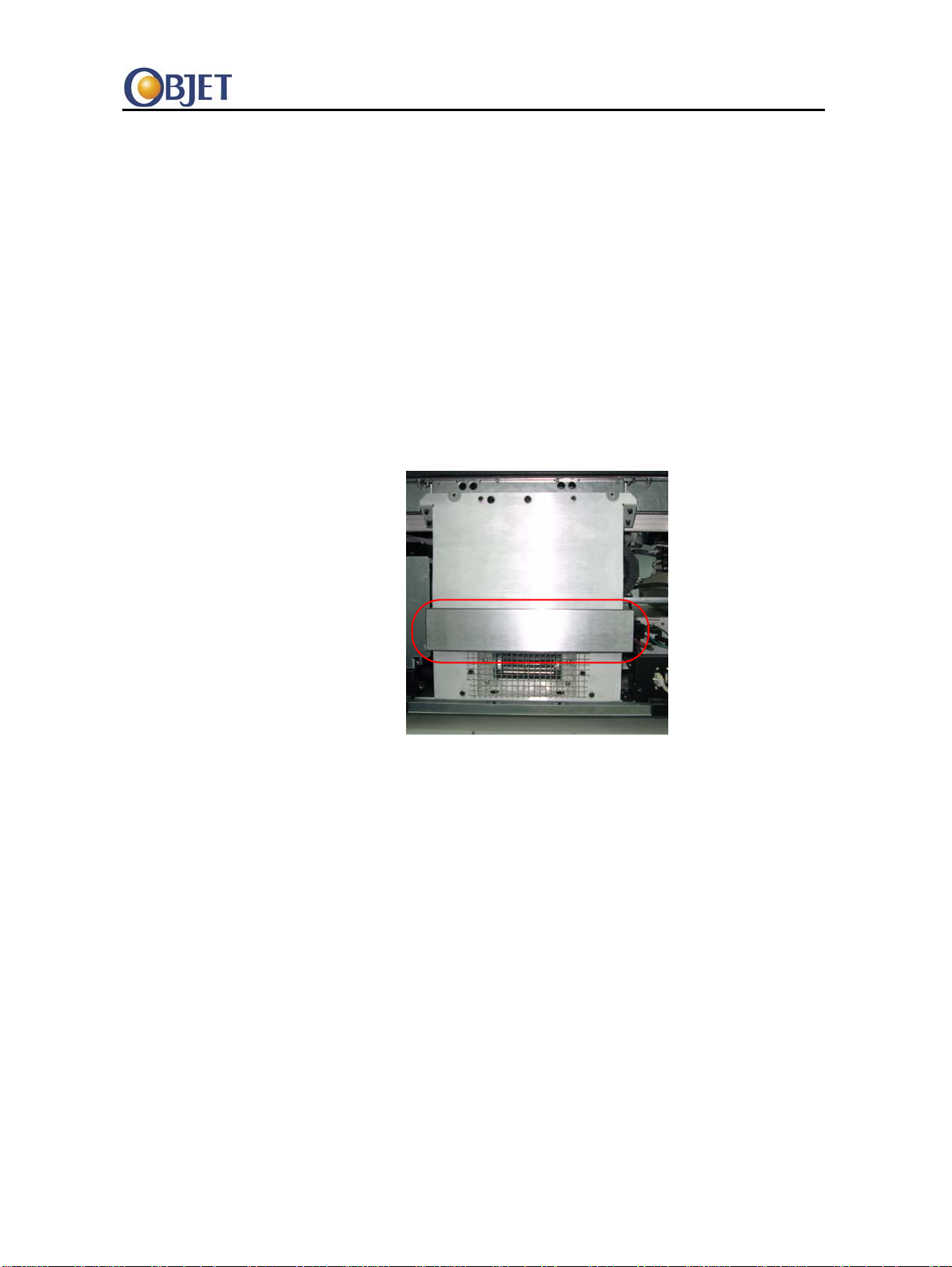
2. Removethefilterfromtheblower.
Figure 1 Filter on Blower
Alaris30 Service Guide
DOC-04204 Rev. A Confidential and Proprietary Information 4
3. Openthepumppanel(nexttotheblower).
Figure 2 Pump Panel—Closed
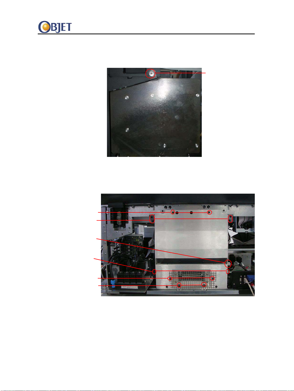
4. Removethetwoscrews,whichsecuretheguardtotheblowerand
removetheguard.
Figure 3 Blower
5. Removetherubbercoverfromeachofthebasescrews.
Screw
Guard screws
Base screws
Top screws
Side screws
Connector
Wing nuts

Alaris30 Service Guide
DOC-04204 Rev. A Confidential and Proprietary Information 5
6. Removethefollowingscrews,whichsecuretheblowertotheframe:
•Basescrews
•Topscrews
•Sidescrews(twoscrewsforeachside).
7. Loosenthewingnuts(oneoneachside).
8. Disconnecttheconnector.
9. Lifttheblowerbythewingnutsandremovetheblowerfromthe
printer.
10. Loosenthe4thumbscrewsthatfastenthez‐axiscovertotheprinter
andremovethecover.
Figure 4 Z-axis Cover—Screws Circled
Figure 5 Remove Z-axis Cover
11. Discard(accordingtolocalregulations)anywasteresidueinthe
coverandwipeitcleanwithapapertowel.
12. Replacethez‐axiscoverandrefastenthethumbscrews.
13. Reattachtheblower.

Alaris30 Service Guide
DOC-04204 Rev. A Confidential and Proprietary Information 6
14. Insertthecarbonfilterintotheblower
15. Closethepumpspanel.
16. Reattachthebackpanel.
Alaris30 Service Guide
DOC-04204 Rev. A Confidential and Proprietary Information 7
3 Leaks and Spills
Aspartofyearlymaintenance,theserviceengineerchecksforsupportor
modelmaterialleaks.Inparticular,leakedprintingmaterialoftencollects
inthereservoirunderneaththeblower.
3.1 Tools
•Papertowels
• Cleaningsolution(isopropylalcohol)
3.2 Procedure
1. Removetheprintercoversandtheblower.
2. Inspectforleakedprintingmaterialinsidetheprinter.Besureto
lookinthefollowinglocations:
•Underthepumpspanel
•Underandaroundthecheckvalves
•Nearthewipermotor(locatedunderneaththebuildtray)and
neartheprintercomputer
•Underthematerialsdrawer
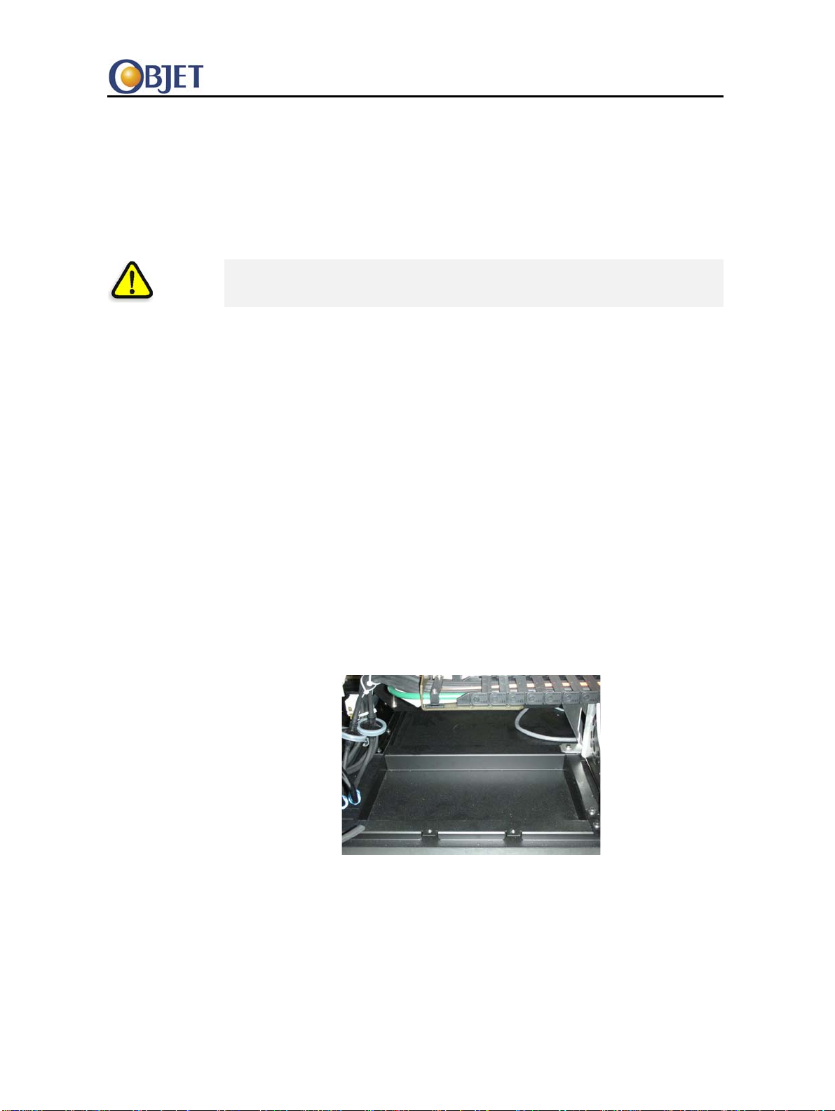
•Undertheblower
Figure 6 Reservoir Underneath Blower
Warning:Be sure to read and understand “” on page 1.

Alaris30 Service Guide
DOC-04204 Rev. A Confidential and Proprietary Information 8
Leak Cleaning 3. Ifyoudetectaleak,dothefollowing:
•Locatethesourceoftheleakandrepairit.
•Forsmallerleaks,soakupanyleakedprintingmaterialusing
papertowels.
•Forlargerspills,followtheinstructionsintheMaterialSafety
DataSheet(MSDS)andanylocalregulations.
4. Cleananyresidueusingapapertowelwettedwithcleaningsolution
(isopropylalcohol).
5. Ifpeopleareincontactwiththearea(ascomparedtoareaswith
electronics),rinsewithsoapandwater,andthendry.
6. Disposeofthewasteinaccordancewithlocalregulations.

Alaris30 Service Guide
DOC-04204 Rev. A Confidential and Proprietary Information 9
4 Model Cooling Fan Inspection
Inspectionproceduretoverifythatthemodelcoolingfansareoperational.
4.1 Procedure
1. MakesuretheprinterispoweredON.
2. IntheAlaris30software,selectMaintenance>Actuatorsand
Sensors.TheActuators&SensorsControlwindowopens.
Figure 7 Actuators & Sensors Control Window
3. IntheFanssection,clickOnfortheModelFan(iftheModelFansare
currentlyoff).
The UV lamp and head driver cooling fans do not require inspection, since they
contain speed sensors and their status is routinely checked by the printer.

Alaris30 Service Guide
DOC-04204 Rev. A Confidential and Proprietary Information 10
4. Visuallyinspectthemodelcoolingfansandverifythefollowing:
•Thebladesareturningrapidly
•Thefansaremovingairandnotcloggedwithdust.
Figure 8 Model Cooling Fans
Other manuals for Alaris30
2
Table of contents
Other Objet 3D Printer manuals


