OBLO Living DOC400 User manual

USER MANUAL
Home Automation Gateway
DOC400


Congratulations and thank you for purchasing the DOC400 OBLO Living Product Home
Automation Gateway. The following product description will provide you with useful infor-
mation about its use.
ATTENTION!
Note regarding the integration of a new gateway:
In order to add the gateway to your account, please use the password and the
security ID given on page 27 of this user manual.

4
CONTENTS
1. OBLO LIVING HOME AUTOMATION GATEWAY………………………………………………………5
2. TECHNICAL INFORMATION…………………………………………………………………………………..6
3. CONFIGURING THE OBLO LIVING HOME SYSTEM………………………………………………..7
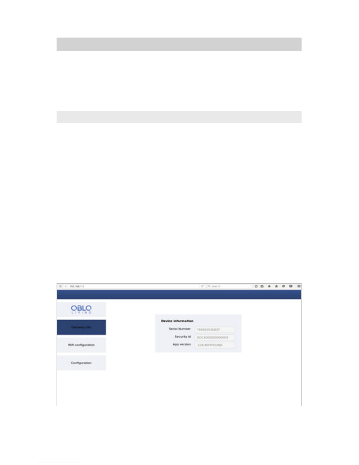
3.1 CONNECTING THE GATEWAYS TO THE HOME NETWORK…………………………………..7
3.2 REGISTERING THE USER’S ACCOUNT…………………………………………………………………………..8
3.3 ADDING THE GATEWAY TO THE USER ACCOUNT………………………………………………………..8
3.4 HOME INSTALLATION…………………………………………………………………………………………………..9
3.5 MANAGING Z-WAVE COMPONENTS…………………………………………………………………………..10
3.5.1 Adding Z-Wave device……………………………………………………………………………………10
3.5.2 Removing Z-Wave device………………………………………………………………………………..10
3.5.3 Closing Z-Wave network…………………………………………………………………………………10
3.5.4 Z-Wave learn mode………………………………………………………………………………………..11
3.5.5 ZigbeeComponents………………………………………………………………………………………..11
3.6 RESETTING THE GATEWAY, NETWORK AND FACTORY SETTINGS……………………….11
3.7 HOME AUTOMATION GATEWAY BUTTON ASSIGNMENTS………………………………….12
4. CLIENT APPLICATION MANAGER………………………………………………………………………..13
4.1 ACCOUNT MANAGEMENT………………………………………………………………………………….13
4.1.1 Creating a new account…………………………………………………………………………………..13
4.1.2 Updating account information…………………………………………………………………………14
4.2 HOMECONFIGURATION…………………………………………………………………………………….15
4.2.1 Adding a gateway to the account…………………………………………………………………….15
4.2.2 Removing a gateway from an account……………………………………………………………..16
4.2.3 Home installation…………………………………………………………………………………………..16
4.2.4 Devicemanagement……………………………………………………………………………………….17
4.2.5 Adding a new device………………………………………………………………………………………18
4.2.6 Removing a device…………………………………………………………………………………………18
4.2.7 Removing the device from a previous network…………………………………………………18
4.2.8 Updating the device name and location…………………………………………………………..19
4.2.9 Expanding functional access in learning mode………………………………………………..19
4.2.10 Setting the timeframe for registration & deregistration……………………………………..19
4.3 CONTROLLING DEVICES……………………………………………………………………………………19
4.3.1 Controlling devices by type…………………………………………………………………………….19
4.3.2 Controlling devices by location……………………………………………………………………….20
4.3.3 Advanced device configuration………………………………………………………………………20
4.3.4 Special features……………………………………………………………………………………………..21
4.4 CONFIGURINGSCENARIOS………………………………………………………………………………..21
4.4.1 Creating New Scenarios………………………………………………………………………………….21
4.4.2 Executing a scenario………………………………………………………………………………………23
4.4.3 Editing a scenario…………………………………………………………………………………………..23
4.4.4 Deleting a scenario………………………………………………………………………………………..23
4.4.5 Disabling a scenario……………………………………………………………………………………….24
4.4.6 Enabling email notification……………………………………………………………………………..24

5
1. OBLO LIVING HOME AUTOMATION GATEWAY
OBLO Living Home Automation Gateway is intelligent multifunctional device that provides man-
agement for the home automation systems. It can control large number of the home automation
devices in the user’s home, such as alarms, outlets, thermostats and more. OBLO Living gateway
is capable to control devices that use one of the following communications protocols: Z-Wave,
ZigBee and IP.
Main feature of the gateway is to fetch states of dierent home automation household appliances
and sensors as well automatically change them based on the user predefined rules.
User can manage Home Automation System using OBLO Living client application for:
• iOS 7.0 (Apple devices) available on Apple Store
• Android 4.0 available on Play Store
Using client applications, users can control their household devices and manage their accounts as
well as the list of their gateways and configuration options.
A cloud-based web application is available for gateway remote access. Using this application, users
can manage account and gateway updates. The cloud service can be found at https://cloud.oblo.rs.
The gateway has two buttons and one LED:
• FRONT button is used to manage Home Automation devices.
• BACK button is used to reset user data, reset the gateway network and reset the gateway to
factory default settings.
• RGB LED inform about gateway status
Use of these buttons is described in more detail in the corresponding sections of this manual (page
12).

6
2. TECHNICAL INFORMATION
Specifications:
• RJ45 Ethernet port
• FRONT and BACK button
• RGB LED for user interaction
Power Supply:
• Adapter (AC/DC): input ~100-240 V, 0.3 A, 50/60 Hz output DC 5 V, 2 A
• Micro USB port
Wireless:
• Wireless network 802.11n, 2.4Ghz compatible
• Z-Wave @868MHz for EU market
• ZigBee Pro @2.4GHz
Operating temperature:
• Indoor usage only, 40° C max
WARNING!
The 5V port of this unit is to be connected only to the devices whose power feeding meets the re-
quirements for SELV (Safety Extra Low Voltage) and complies with Limited Power Source according
to IEC 60950-1.
!

7
3. CONFIGURING THE OBLO LIVING HOME SYSTEM
Configuring the OBLO Living Home system consists of four basic steps.
1. Connecting the gateways to the home network
2. Registering the user’s account
3. Adding the gateway to the user account
4. Home installation
3.1 CONNECTING THE GATEWAYS TO THE HOME NETWORK
The gateway can be connected to the local home network using Ethernet or WLAN connections.
Once connected to power supply, the gateway start operations (after 2 min.) and connect to the
home network with the help of Ethernet connections, if the connected Ethernet RJ45 cables are
working. If an Ethernet cable is not available, the gateway starts in WLAN Access Point mode, which
is only used to configure the wireless network. RGB LED blinks as long as the gateway is in Access
Point mode.
Connect the smart phone or tablet with the gateway access point to access the gateway configura-
tion page. The SSID for the gateway has been assigned an identifier that will be displayed using the
identifier “SSID:DOC400…”. Create a connection to the access point and enter „http://192.168.1.1”
as the URL in the browser for the smart phone or tablet. The page that opens allow an SSID and
serial number for the home network’s router to be entered (Notice the correct spelling!). Internet
connection is required in order to register the gateway with the cloud service. The gateway can only
be enabled and afterwards receive software updates.

8
3.2 REGISTERING THE USER’S ACCOUNT
Users can authenticate gateways and mobile apps with the OBLO Living Home Automation using
the user account. The user name for the account is the email address that is required for register-
ing the account. Account registration may be done through the client or the web application from
https://cloud.oblo.rs.
To create a new user account using the client application, the user must first make sure that their
smart phone or tablet is connected to the local wireless network (WLAN). The OBLO Living Home
Automation application can then be started. Choose the Create New Account option on the login
dialog and follow the setup wizard’s instructions.
OBLO Living Home Automation application ask for a valid email address to be entered as the user
name. This email address is used to send a link to activate the account. Additional legal information
will be provided after tapping on the General Terms and Conditions and Data Protection Provisions
link. Confirm the usage conditions to continue.
Additional account and personal information can be entered as part of following those instructions.
Entry of all information regarding the account details is optional. It may be changed at any time. The
asterisk (*) indicates mandatory entries.
Once the user name and password have been validated, an activation link is sent to the user by
email. It may be several minutes before that email message arrives. Confirm the activation of the
account by tapping the link in the message. (Check your Spam folder, just to be sure.)
Additional information about account registration through the cloud application can be found in
Section (from page 15).
3.3ADDING THE GATEWAY TO THE USER ACCOUNT
Either a mobile application or a cloud service can be used to associate a gateway with a user
account. To make the association using a mobile application, open the OBLO Living Home app
and log into the user account. Select the Home Installation option from the main menu. On the
subsequent Home Installation screen, select the Add Gateway option in the upper right corner. The
new Gateway wizard will start and request a gateway SSID (secure SID), a password and a symbolic
gateway name (page 15).
• The S/N (Serial Number) is a unique identifier for every gateway device. It consist of 12 char-
acters (e.g. as 7CDD9078CC00) and can be found on the device and in it packaging.
• The SID (Secure ID) is a unique, secret identifier for a gateway. It consist of 16 characters (e.g.
DOC400012H5J93AC). This number can be found on the bottom case of gateway.
This number can be found on the last page of the manual.

9
As soon as the required information has been entered, tap the button to continue. When gateway
information validity is verified and if gateway is not assigned to another user account, then will be
added to user account.
The gateway must be connected with the same local network used with mobile phone with OBLO
Living client application.
Additional information about adding a gateway to an account through the client application can be
found in Section 4.2.
3.4 HOME INSTALLATION
The Gateway Configuration option become available after tapping the Home Installation option on
the client’s main menu. To make the Options menu appear, tap and hold the Gateway button on
the Home Installation screen. Select the Edit option from that menu. The option starts the Gateway
Configuration wizard.
In the first step, the user can change the gateway name. The gateway SSID cannot be changed
once it has been added to the user account. Tap the button to continue to the Setup Home
Assignments step.
The user can manage the associated floors and rooms in a subsequent step. Adding the floors and
rooms can be accessed by tapping the + option in the upper right corner. Tapping this control and
holding it for a moment can remove each room and each floor. Once the user is happy with the
home assignments, tap the button to continue to the Device Management step.
In this step, the user can add new devices by tapping the Find Devices button. This action place
network in a mode, which can add devices. Read the operating instructions for the selected compo-
nents to do so. From the same screen, devices can be removed by tapping the device and holding it
for a longer time, and then selecting the Delete option (regarding this, see the respective operating
instructions).
Z-Wave devices that have not been removed from the previous network must be removed first.
This can be done using the Exclude Device option on the Settings menu in the upper right
corner of the screen (see page 17).
Once the configuration of the gateway has been completed, tap the button to complete the
Home Installation wizard process.
Additional information about configuring a gateway and mobile device through the mobile app can
be found in Section 4.2.1.

10
3.5MANAGING Z-WAVE COMPONENTS
Home Automation Gateway is a Z-Wave Plus security enabled gateway. It can be included and
operated in any Z-Wave network with other Z-Wave certified devices from other manufacturers
and/or other applications. All non-battery operated nodes within the network will act as repeaters
regardless of vendor to increase reliability of the network.
3.5.1 Adding Z-Wave device
Before adding new Z-Wave device, make sure that device was removed from previous network. To
add new Z-Wave device to the network, user must open Z-Wave network for inclusion. There are
two ways to open the network:
• Using mobile application: Tap the Home Setup option on the mobile application’s main menu
and select the desired gateway button by tapping it and holding it until add device menu ap-
pears. Go to Add Device to introduce a new component. Select Find devices.
•
• Using gateway button: Short press FRONT button two times on the gateway.
If the network has been opened for inclusion, the LED will blink blue once per second. During the
time network is open, user must activate learn mode on the device according to specific device
instruction related with the inclusion in the Z-Wave networks. To do so, follow the instructions in
the device’s manual.
When another controller is included in OBLO Living Gateway it will initiate network information
replication from the OBLO Living Gateway to the included controller.
3.5.2 Removing Z-Wave device
To remove Z-Wave device from the network, user must open Z-Wave network for exclusion. There
are two ways to open the network for exclusion:
• Using mobile application: Tap the Home Setup option on the mobile application’s main menu
and select the desired gateway button by tapping it and holding it until add device menu ap-
pears. Go to Add Device and select Exclude Device option from the Settings menu in the upper
right corner of the screen.
• Using gateway button: short press FRONT button four times.
During this time, the LED will blink blue five times per second. The corresponding Z-Wave device
must be removed from the network during this blinking period. To do so, follow the instructions in
the respective user’s guide.
The procedure for removing controller device is the same as for other devices.

11
3.5.3 Closing Z-Wave network
The Z-Wave network is closed by pressing FRONT button 2 times while network is open or by using
the client application. When the network is closed, the LED will turn o.
3.5.4 Z-Wave learn mode
To enable Home Automation Gateway to receive information from another controller, start learn
mode. To initiate learn mode Short press on BACK button twelve times. When controller enters
learn mode it will lose all Z-Wave devices that were previously included. Controller replication is
implemented at minimum level and it is enabled by placing the controller in the learn mode.
To include Home Automation Gateway to another controller network, start inclusion on the in-
clusion controller and start Learn mode on Home Automation Gateway by short press on BACK
button twelve times.
Home Automation Gateway will ignore any basic command class commands from devices.
Home Automation Gateway supports Association Command Class. It implements one association
group, which is Lifeline group with grouping identifier equal to 1. This group returns Device Reset
Locally notification when the device is reset. Maximum number of devices that can be added to the
group is 1. To control association, if the device supports association, go to advanced view of the de-
vice. Click on Node ID field of the devices to associate and type all Node IDs separated by comma.
To control multichannel association of the device go to advanced view of the device. Click on Node
ID field of the device and in the field enter Node ID/Endpoint of the device to associate. For example
26/2 where 26 is a Node Id and 2 is Endpoint.
To remove/replace failed node from client application main screen select home setup, select a
gateway and tap on Add device. Tap and hold the failed device. A popup will appear with remove
and replace options. To reset Z-Wave to default settings perform factory reset of the Gateway.
3.5.5 Zigbee Components
Adding ZigBee devices is done in the same manner as Z-Wave devices.
ZigBee learning mode
Follow the same procedure for the Z-Wave mode in order to register ZigBee components. The LED
also provide information about the status of the gateway.
In the Access Point mode, LED blinks blue one time per second. When starting the gateway, only the
during boot loading LED light blue. Booting takes roughly 2 minutes.

12
3.6RESETTING THE GATEWAY, NETWORK AND FACTORY SETTINGS
Reset user preferences
This function permit to reset all user configuration settings (all user data, settings and devices will
be erased). Short press on FRONT button six times reset user preference. During reset LED blink
red two times per second.
Restart the network
This function permit the user to reset the network connection settings to factory settings. Once
the network has been restarted, the gateway will be restarted. Once the network cable has been
connected to the gateway after the network has been restarted, it continue to use the network con-
nection. If the network cable is not connected to the gateway, the gateway enters in Access Point
mode. When press the BACK button three times gateway reset the network configuration. During
reset LED blink red five times per second.
Factory settings
The factory settings function reset the gateway to the state in which it was delivered (all user data,
settings and devices will be erased). Short press on BACK button nine times gateway will reset to
factory settings. During reset LED blink red one time per second.
3.7 HOME AUTOMATION GATEWAY BUTTON ASSIGNMENTS
The Home Automation Gateway has 2 buttons (FRONT and BACK button). Certain features will
be activated by tapping and holding the button for longer periods of time. Both buttons has been
assigned a special feature (Figure 1).
• FRONT button: Managing the Z-Wave and ZigBee network
• BACK button: System settings (reset, learning mode…)
BACK button FRONT button RGB LED
Reset user preferences Short press 6x Blink red 2x per second
Network reset Short press 3x Blink red 5x per second
Factory reset Short press 9x Blink red 1x per second
Closing network Short press 2x Light green IDLE
Node inclusion Short press 2x Blink blue 1x per second
Node exclusion Short press 4x Blink blue 5x per second
Network learning mode Short press 12x Blink blue 2x per second
Boot mode Long press 5
seconds
Blink red 2x per
second
Light blue
IDLE
Normal mode Light green IDLE
Error mode no network Blink blue 5x per second
System error mode Light purple IDLE
AP mode Blink blue 1x per second

13
4. CLIENT APPLICATION MANAGER
4.1 ACCOUNT MANAGEMENT
4.1.1 Creating a new account
Illustration 1 Illustration 2
1. Tap the Create New Account button on the login dialog (see Illustration 1).
2. Enter a valid email address and the password on the login dialog. An activation link will be
sent to the specified email address (see Illustration. 2).
3. Agree with the General Business Terms and Conditions and Data Protection Provisions and
tap the button . The complete text of the General Business Terms and Conditions and
the Data Protection Provisions can be reviewed by tapping the General Business Terms and
Conditions and Data Protection Provisions button.
Illustration 3 Illustration 4
4. Enter the account details and tap the button. Entries indicated by an asterisk (*) are man-
datory entries. All other entries can also be filled in later (see Illustration 3).
5. Enter the your personal information and tap the button to close the wizard (see Illustration 4).
6. Once the account has been successfully registered, a message with an activation link will
be sent to the email address specified in the account name (make sure to check the Spam

14
folder). Otherwise, a failure notice will be displayed.
7. Confirm the activation link sent in the email message.
4.1.2 Updating account information
Illustration 5 Illustration 6
1. To update the user account information, tap the user icon in the upper right corner of the main
menu and select the Account Settings option (see Illustration 5).
2. The Account Settings wizard will be started.
3. The password for the account can be changed in the first step. To continue changing account
details, tap the button (see Illustration 6).
Illustration 7 Illustration 8
4. Information about the account details can be changed in the second step. All of the entries
are optional. To continue to the third step for updating personal information, tap the button
(see Illustration 7).
5. Personal information can be updated in the third step. All of the entries indicated with an
asterisk (*) are mandatory fields. All other entries are optional (see Illustration 8).
6. Tap the button to complete the Account Settings wizard process.

15
4.2HOME CONFIGURATION
4.2.1 Adding a gateway to the account
Illustration 9 Illustration 10
Illustration 11
User can register more than one gateway on its account
Follow these steps to add a gateway
1. Log into the account that should register the new gateway.
2. Select the Home Installation menu option to open a list of the gateways associated with the
account (see Illustration 9).
3. Tap the Add Gateway option in the upper right corner to start the Home Installation wizard
(see Illustration 10).
4. A gateway can be added to the account in the Add Gateway step.
5. Enter the Secure SID (SID), password (PW) and a name as the gateway information (see
page 27). The gateway may only be added when the correct combination of SID and pass-
word have been entered (see Illustration 11).
6. Tap the button to add the gateway and continue the home configuration process. If the
gateway has been added, a success message will be displayed. Note: an Internet connection
will be required for this option.
7. The home configuration can be setup in the subsequent steps, see Section 4.2.3. Note: gate-

16
way configuration will require a smart phone or tablet that is active in the same network as
the gateway.
4.2.2Removing a gateway from an account
Illustration 12 Illustration 13
Follow these steps to remove a gateway properly.
1. Start the mobile app.
2. Select the Home Installation menu option to open a list of the gateways associated with the
account (see Illustration 12).
3. Find the gateway in the list and tap the gateway button and hold it until the options menu is
displayed (see Illustration 13).
4. Select the Delete option.
5. Confirm execution.
4.2.3Home installation
Configuration of the home network uses the Home Installation wizard, as explained in 5.2.1. The
home gateway must be in the same network as the smart phone or tablet. The home assignments
and device management can be configured using the following options.
1. Login to the account, to which the gateway was added.
2. Select the Home Installation menu option to open a list of the gateways associated with the
account.
3. Find the gateway in the list and tap the gateway button and hold it until the options menu is
displayed.
4. Select the Edit option.
5. Information about the name of the gateway can be changed in the first step. Tap the button
to continue configuring the division of the floor(s).
6. The division of the floor(s) can be configured in the second step. To add a new floor, tap the
+ button in the upper right corner and enter a new floor name. To delete the floor, tap the
opened Floor button and hold it, then tap the Delete option. All of the rooms associated with
the floor will be deleted when the floor is deleted. Devices that are associated with those

17
rooms will be moved into the unknown devices group. A floor name can be changed by tap-
ping on the floor (see Illustration 14).
7. To continue configuring rooms, tap the button.
8. The rooms can be configured in the third step. To add a new room, choose the corresponding
floor from the menu on the menu bar, tap the + option and enter the room name. To delete a
new room, select the floor where the room is located, tap and hold the Room button to open it
and then select the Delete option from the menu. All devices will be moved into the unknown
devices group when the room has been deleted. A room name can be edited by briefly tap-
ping on the room (see Illustration 15).
9. To continue managing devices, tap the button.
Illustration 14 Illustration 15
4.2.4Device management
Illustration 16 Illustration 17
To add a new device, follow Steps 1 through 9 from Section 4.2.3 to open the Home Installation
wizard. To continue directly with the device configuration step, select the Find Devices option, as
described in Section 4.2.5. In that manner, new devices can be added, existing devices removed,
devices from the previous network removed, network switch settings made and device names and
locations managed.

18
Illustration 18 Illustration 19
4.2.5Adding a new device
Please note, that the distance between the gateway and the clients shall not be more than 0.5
meters during integrating in/excluding from the network.
1. To add a device, tap the Find Devices button. This action will open a new window for integrat-
ing the device. The counter in the window will display the amount of time until the network
will be closed again.
2. Integrate the device. This process may vary from device to device. Read the manual for the
device. A guide that indicates how fully-supported devices can be integrated can also be
found by tapping the Help option in the upper right corner of the screen.
3. If a device is added to a network, it will be displayed above the list of devices.
4. A symbolic name can be assigned using the Edit option by tapping on the device button and
holding it and the device can be selected. (see Illustration 17).
Please note that with battery-operated components, a Wake-up function has to be performed after
successful registration with the gateway (the procedure is the same as including the component,
e.g. pressing the button 3x with ZHS04).
In case the range of the nearest repeater is not large enough, please use an additional power repeater.
4.2.6Removing a device
1. To remove a device, tap on the device and hold it while selecting the Delete option.
2. The type of device (ZigBee or Z-Wave) will determine which of the following processes
should be used.
a. In the case of ZigBee devices, deletion merely needs to be confirmed.
b. In the case of Z-Wave devices, the network will be opened for the deletion process. Once
the network has been opened, the device must be deleted manually. Follow the instruc-
tions in the device’s manual for removing the device.
4.2.7 Removing the device from a previous network
1. Tap the setting menu icon in the upper corner and select the Remove Device option (see

19
Illustration 19).
2. When the dialog opens, the network will be opened for removing components. Follow the
procedures for removing the device. Additional information can be found in the user’s manual
for the respective components.
4.2.8Updating the device name and location
By default a device will be assigned a predetermined name consisting of the device type and ID. The
device will not be assigned to a room. To update the parameters (see Illustration 15):
Tap the device symbol and hold it.
1. Update the Edit entry on the Device Information dialog.
2. Choose the device location from the Location list (see Illustration 18).
4.2.9Expanding functional access in learning mode
Access between the gateway and the components to be learned can be extended in learning mode.
Check the corresponding checkbox to do this. (see Illustration 16).
4.2.10 Setting the timeframe for registration & deregistration
1. Open the Settings menu from the Device Configuration screen in the upper right corner and
select Deactivate Network.
2. When the dialog is displayed, enter the descried timeframe for the duration in seconds.
3. Tap the OK button to confirm this action.
4.3CONTROLLING DEVICES
4.3.1 Controlling devices by type
Illustration 20
1. Select the Device by Type option on the application’s main menu.
2. To filter devices by type, choose a type from the menu on the left.
3. To release the filter, tap the home icon in the upper left corner.
4. In addition to filtering by type, a filter by location may also be applied, by choosing the device
location using the option in the upper right corner.

20
5. Each device can be depicted and controlled using its own button in the middle of the appli-
cation screen (see Illustration 20).
6. Advanced device options will be made available by tapping on the device button and holding
it. For more information, see 5.3.3.
4.3.2 Controlling devices by location
Illustration 21 Illustration 22
1. Select the Device by Location option on the application’s main menu.
2. To filter devices by type, choose a location from the menu on the left.
3. To release the filter, tap the home icon in the upper left corner.
4. In addition to filtering by type, a filter by location may also be applied, by choosing the device
type using the option in the upper right corner.
5. Each device can be depicted and controlled using its own button in the middle of the appli-
cation screen (see Illustration 21).
6. Advanced device options will be made available by tapping on the device button and holding
it (see Illustration 22). For more information, see 5.3.3.
4.3.3 Advanced device configuration
Illustration 23
Other manuals for DOC400
2
Table of contents
Other OBLO Living Gateway manuals
Popular Gateway manuals by other brands

Sygonix
Sygonix 1898921 RSL 433 MHz App instruction manual

CITELlink
CITELlink SIP Handset Gateway Installation & configuration guide

Funkwerk
Funkwerk artem ComPoint Butterfly manual

SIMES
SIMES GATEWAY WIFI-108 instruction manual

SKYMICROWAVE
SKYMICROWAVE T-30 user manual

Multitech
Multitech MULTIVOIP MVP-130FXS Specifications