OBLO Living DOC400 User manual

USER MANUAL
Home Automation Gateway
DOC 400


TABLE OF CONTENTS
1. IMPORTANT SAFETY INFORMATION....................................... 4
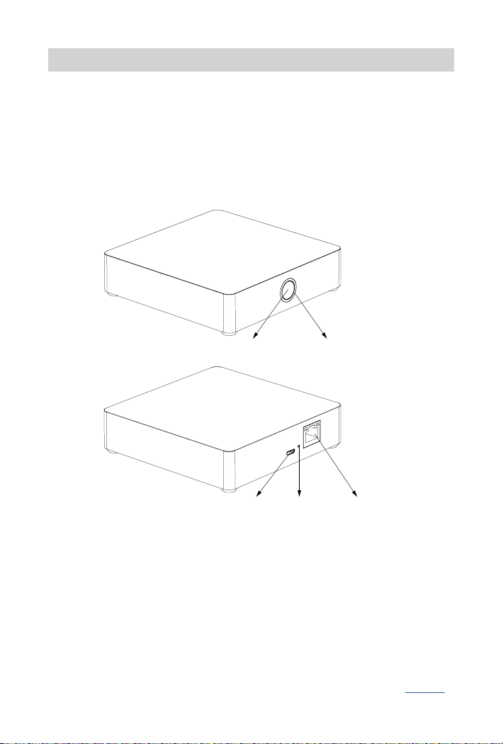
2. DEVICE DESCRIPTION ................................................... 5
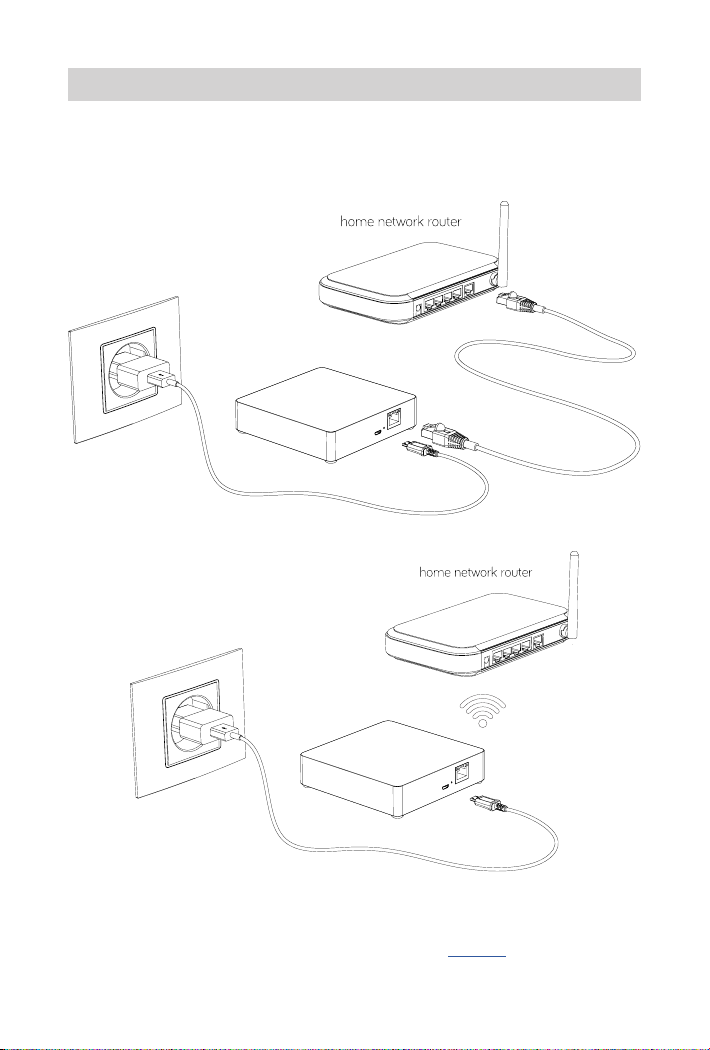
3. INSTALLATION OF THE OBLO LIVING GATEWAY ............................6
3.1 WIFI CONFIGURATION OF THE GATEWAY....................................................................................................7
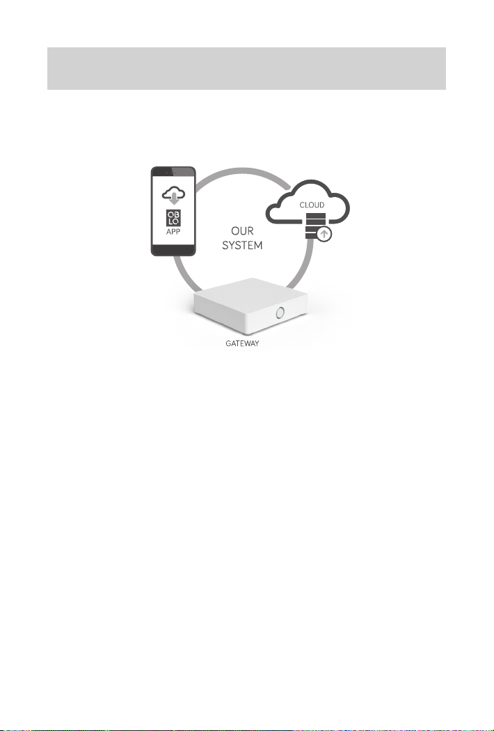
4. CONFIGURING THE OBLO LIVING HOME AUTOMATION SYSTEM ............. 8
4.1 INSTALL OBLO LIVING CLIENT APPLICATION........................................................................................... 9
4.2 CREATE USER ACCOUNT............................................................................................................................................9
4.2.1 Create user account by using client application ..............................9
4.2.2 Create user account by using web application ..............................10
4.3 ADD THE GATEWAY TO THE USER ACCOUNT........................................................................................ 11
4.3.1 Add the gateway by using client application ................................11
4.3.2 Add the gateway by using web application .................................11
4.4 HOME SETUP.......................................................................................................................................................................12
5. DEVICE MANAGEMENT ..................................................13
5.1 MANAGE DEVICES BY USING CLIENT APPLICATION.......................................................................13
5.1.1 Add a device to the gateway...............................................13
5.1.2 Remove a device .........................................................14
5.1.3 Update device name and location..........................................15
5.2 MANAGE DEVICES BY USING GATEWAY’S MAIN BUTTON.......................................................... 15
5.2.1 Add a device to the gateway ...............................................15
5.2.2 Remove a Z-Wave device..................................................15
6. CONTROLLING AND MONITORING DEVICES ...............................15
6.1 DEVICES BY LOCATION...............................................................................................................................................15
6.2 DEVICES BY TYPE.............................................................................................................................................................16
6.3 ADVANCED DEVICE CONFIGURATION..........................................................................................................16
7. SCENE MANAGEMENT ...................................................17
7.1 CREATE NEW SCENE......................................................................................................................................................17
7.2 RUN THE SCENE...............................................................................................................................................................20
7.3 EDIT THE SCENE ..............................................................................................................................................................20
7.4 DELETE THE SCENE....................................................................................................................................................... 21
7.5 DISABLE THE SCENE.....................................................................................................................................................21
8. RESET NETWORK CONFIGURATION .......................................21
9. RESET USER PREFERENCES ..............................................21
10. FACTORY RESET ........................................................21
11. BUTTONS/FUNCTIONS .................................................22
12. TECHNICAL DATA ......................................................22
13. DECLARATIONS OF CONFORMITY .......................................22
March 10th 2017

4
Congratulations and thank you for purchasing OBLO Living Home Automation
Gateway device. Below you will find useful operating guidelines.
WARNING!
The 5V port of this unit is to be connected only to the devices whose power feeding
meets the requirements for SELV (Safety Extra Low Voltage) and complies with
Limited Power Source according to IEC 60950-1.
1. IMPORTANT SAFETY INFORMATION
Before using OBLO Living Home Automation Gateway, please read the following information to
avoid any potential dangers:
1. Read the instructions carefully and follow the precautions in this manual. All mains connec-
tions must be carried out by a trained and qualified person
2. Only use the original mains adaptor supplied with the device
3. Disconnect the device from mains (mains chargers) before cleaning. Clean device with a
damp cloth, do not use detergents
4. Do not use device in gas-filled environments
5. Do not place the device near heat sources
6. Do not expose the device to direct sunlight
7. Do not place cables and/or power supplies under heavy objects. Also, avoid routes near sharp
or abrasive objects and walkways
8. Keep out of reach of children
9. Do not carry out any maintenance on the device, instead contact your supplier
10. Make sure that ventilation slots and the cooling unit are not covered
11. As the device generates heat, this can lead to discoloration on the surface of furniture. Make
sure there is at least 10cm of clearance around the device
12. The device must not be located in the rooms with a high level of humidity e.g. kitchen, bath-
rooms, etc.
13. Under no circumstances should you open the device or the mains adaptor. This must only be
carried out by a qualified engineer
14. Do not touch any contacts on the device with your fingers or metal objects. This could cause
a short circuit
15. Do not handle the device when your hands are wet due to risk of electric shock

5
2. DEVICE DESCRIPTION
OBLO Living home automation gateway takes central place in home automation system.
Combined with OBLO client (Android/iOS/HTML) applications and OBLO cloud service it provides
a turnkey platform that covers lighting, security, safety, energy management and other aspects of
the fast-growing home automation markets.
By supporting the most popular wireless communication protocols today (Zigbee, Z-Wave, IP),
OBLO Living gateway communicates with connected devices and enables users to monitor and
control their home.
Illustration 1: OBLO Living home automation gateway
OBLO Living home automation gateway consists of:
• FRONT (main) button, which is used to manage home automation devices
• BACK button, which is used to reset user data, reset the gateway network, reboot the gateway
and reset the gateway to factory default settings
• LED indicator informs user about gateway status
• Power supply socket
• Ethernet
Use of these buttons is described in more detail in the corresponding section of this manual (page 22).
Front button
FRONT
BACK
Power supply socket Back button Ethernet
LED indicator

6
3. INSTALLATION OF THE OBLO LIVING GATEWAY
In order to install your OBLO Living gateway, please follow next steps:
1. Plug in the Home Automation Gateway to the AC power supply
2. Connect the Gateway to the home network router by using Ethernet ( Illustration 2) or WiFi
Connection (Illustration 3)
Illustration 2: Ethernet connection
Illustration 3: WiFi connection
In case you have connected your gateway device to the home network router by using Ethernet
cable, the installation process is done and you can proceed to the Section 4 (Configuring the OBLO
Living home automation system).

7
3.1 WIFI CONFIGURATION OF THE GATEWAY
In case you would like to connect the gateway device to the home network router by using WiFi
connection, please follow next steps:
1. After powering up, the gateway enters AP (Access Point) mode if Ethernet cable is not con-
nected. In AP mode LED will blink blue. In this mode gateway creates its own WiFi network
that allows the end user to configure it for connection to home network router over WiFi
(gateway’s SSID or network name is printed on the label on the back side of the device)
2. Connect your client device (PC, tablet or smart phone) to the WiFi network created by gateway
3. In web browser of your client device launch default IP address printed on the label on the
back side of the gateway (typically 192.168.1.1). Device information page should be displayed
as shown in Illustration 4
Illustration 4
4. In main menu select “WiFi configuration” page as shown in Illustration 5, after which gateway
should list all available WiFi networks in your home
Illustration 5
5. After selecting your home network router’s WiFi network, type in the password and press
“Apply” button to finish WiFi configuration of your gateway
6. Upon successful operation LED should go green indicating that your gateway is connected to
your home network router’s WiFi network. Otherwise, repeat the procedure starting from step 1

8
4. CONFIGURING THE OBLO LIVING HOME AUTOMATION
SYSTEM
OBLO Living Home Automation system consists of:
• OBLO Living client application
• OBLO Living home automation gateway
• OBLO Living cloud
Illustration 6: Our System
OBLO Living client application is intuitive and easy to use. Its comfortable graphical user interface
will smoothly guide users through the process of configuration of their space. The app can be used
both in-home or remotely – it is smart enough to connect to the gateway directly if possible, to
ensure the best user experience.
OBLO Living home automation gateway takes central place in home automation system.
Combined with OBLO client (Android/iOS/HTML) applications and OBLO cloud service it provides
a turnkey platform that covers lighting, security, safety, energy management and other aspects of
the fast-growing home automation markets.
OBLO Living cloud plays an important role in OBLO home automation system, since it enables
home control outside local network. Built around modern web technologies, it ensures the highest
security and robustness with the lowest latency in home automation communication chain. It also
allows monitoring and controlling of the home from any browser-based device.
Please follow next steps for configuring OBLO Living Home Automation system:
1. Install OBLO Living client application
2. Create user account
3. Add the gateway to the user account
4. Home setup

9
4.1 INSTALL OBLO LIVING CLIENT APPLICATION
In order to start configuring OBLO Living home automation system, the user needs to install OBLO
Living client application. By using client application, users can control their household devices and
manage their accounts as well as the list of their gateways and configuration options.
OBLO Living client app is available for download at the Apple and Google application stores.
4.2 CREATE USER ACCOUNT
Account registration may be done in two ways:
1. By using client application
2. By using web application at https://cloud.oblo.rs
4.2.1 Create user account by using client application
Please follow next steps in order to create new account:
1. To create a new user account by using client application make sure that your smart phone or
tablet is connected to the Internet and start the application.
2. Tap the “Create new account” button on the login dialog (see Illustration 7)
Illustration 7 Illustration 8
3. Enter a valid email address and the password on the login dialog (Illustration 8)
4. Agree with Terms of service and Privacy Policy and tap the button . The complete text of
Terms of service and Privacy Policy can be reviewed by tapping the “Terms of service” and
“Privacy Policy” buttons
5. Enter the account details and tap the button . Entries indicated by an asterisk (*) are man-
datory entries. All other entries can also be filled in later (see Illustration 9)
6. Enter your personal information and tap the button to close the wizard (see Illustration 10)

10
Illustration 9 Illustration 10
7. Once the account has been successfully registered, a verification link will be sent to the email
address specified in the account name (make sure to check Spam folder). Otherwise, a failure
notice will be displayed
8. Confirm the activation link sent in the email message
4.2.2 Create user account by using web application
Please follow next steps in order to create new account:
1. Visit https://cloud.oblo.rs
2. Tap the “Don’t have an account” button on the login dialog (see Illustration 11).
3. Enter your personal and login information on the login dialog (see Illustration 12).
Illustration 11 Illustration 12
4. Agree with Terms of service and Privacy Policy and tap the button REGISTER. The complete
text of Terms of service and Privacy Policy can be reviewed by tapping the “Terms of service”
and “Privacy Policy” buttons
5. Once the account has been successfully registered, a message with an activation link will be
sent to the email address specified in the account name (make sure to check Spam folder).
Otherwise, a failure notice will be displayed.
6. Confirm the activation link sent in the email message

11
4.3ADD THE GATEWAY TO THE USER ACCOUNT
The gateway can be added to the user account in two ways:
1. By using client application
2. By using web application
NOTE: More than one gateway can be added to the user account.
4.3.1 Add the gateway by using client application
Please follow next steps in order to add the gateway to the user account:
1. Make sure that your smart phone/tablet and the gateway are active within the same network
2. Open the OBLO Living application and log into the user account
3. Select Home Setup option from the main menu (Illustration 13)
4. On the Home Setup screen tap the “Add gateway” button in the upper right corner (Illustration 14)
Illustration 13 Illustration 14
5. Enter required gateway information:
a. Security ID – is a unique, secret identifier for a gateway. It consists of 16 characters (com-
bination of letters and numbers) and can be found on the back side of the Safety Infor-
mation card that comes in a box together with your gateway device.
b. Serial number – a unique identifier for every gateway device. It consist of 12 characters
(e.g. CDD9078CC00) and can be found on bottom of the device
c. Name – choose a name for your gateway
6. Tap the button to add the gateway and continue the home configuration process
7. If the gateway has been added, a success message will be displayed
4.3.2 Add the gateway by using web application
Please follow next steps in order to add the gateway to the user account:
1. Visit https://cloud.oblo.rs and log into the user account
2. Select My equipment option from the main menu
3. On the My equipment screen tap the button in order to add the gateway to the user
account ( see Illustration 15)

12
Illustration 15
4. Enter required gateway information:
a. Security ID – is a unique, secret identifier for a gateway. It consists of 16 characters (com-
bination of letters and numbers) and can be found on the back side of the Safety Infor-
mation card that comes in a box together with your gateway device.
b. Serial number – a unique identifier for every gateway device. It consist of 12 characters
(e.g. 7CDD9078CC00) and can be found on bottom of the device
c. Name – choose a name for your gateway
5. Tap the SAVE button to add the gateway and continue the home configuration process. If the
gateway has been added, a success message will be displayed
4.4HOME SETUP
The user can setup its smart home by using OBLO Living client application. To setup the home,
please follow next steps:
1. Make sure that your smart phone/tablet and the gateway are active within the same network
2. Log in to the account to which the gateway was added
3. Select Home Setup option from the main menu to open a list of the gateway devices asso-
ciated with the account
4. Find the gateway in the list and tap the gateway button to open the options menu
5. Select the Edit option
6. In the first step, the user is able to change the name of the gateway. Tap the button to
continue managing the associated floors and rooms
7. In the second step, the user can manage associated floors:
a. To add a new floor, tap the button + in the upper right corner and enter a floor name
b. To delete the floor, tap the floor button and hold it until the delete option appears.
NOTE: All of the rooms associated with the floor will be deleted once the floor is deleted.
Devices associated with those rooms will be unsorted.
c. To change the floor name, briefly tap on the existing floor name (Illustration 16)
8. To continue managing rooms, tap the button :
a. To add a new room, choose the floor at which you want to add the room and tap the
button + in the upper right corner to enter a room name

13
b. To delete the room, select the floor at which the room is located, tap and hold the room
name until the delete option appears
NOTE: Devices associated with the deleted room will be unsorted.
c. To change the room name, briefly tap on the existing room name (Illustration 17)
Illustration 16 Illustration 17
9. Once you are satisfied with the home configuration, tap the button to continue to Device
Management section.
5. DEVICE MANAGEMENT
To manage devices, the user should choose one of the following ways:
1. By using client application (recommended way to manage devices)
2. By using gateway’s main button
5.1 MANAGE DEVICES BY USING CLIENT APPLICATION
In order to open Device management section select Home setup option from the application’s main
menu and by tapping gateway’s button select option Add device.
In the Device Management section the user is able to:
1. Add a device to the gateway
2. Remove a device
3. Update device name and location
5.1.1 Add a device to the gateway
Please follow next steps in order to add a new device to the gateway:
1. Tap the “Help” button in the upper right corner
2. Select the device which you want to add to the gateway and read instructions for adding the
device (Illustration 18)

14
3. After having read the instructions, tap the “Find devices” button in the upper left corner. This
action will open a new window for integrating the device. The remaining time for device inte-
gration will be displayed (see Illustration 19)
4. Add the device based on manufacturer’s instructions, since the process may vary from device
to device
5. Once the device is added to network, it will be displayed among the list of devices
NOTE: In order to add a new Z-Wave device to the network, make sure that the device is removed
from the previous network first (see manufacturer’s instructions).
Illustration 18 Illustration 19
5.1.2 Remove a device
Please follow next steps in order to remove a device:
1. Tap on the device name and hold it until the “Delete” option appears (see Illustration 20)
2. The type of device ( ZigBee or Z-Wave) will determine which of the following processes
should be used:
a. In case of ZigBee device, you just need to confirm deletion
b. In case of Z-Wave device, the network will be opened for exclusion process. Once the
network is opened, the device needs to be excluded manually according to manufacturer’s
instructions (see Illustration 21)
Illustration 20 Illustration 21

15
5.1.3 Update device name and location
To update device name and location, please follow next steps:
1. Tap on the device name and hold it until the “Edit” option appears
2. Tap on the “Edit” button
3. In the new dialog, change the device name and choose the device location from the drop down list
4. Tap the button “Done” in the upper right corner
5.2 MANAGE DEVICES BY USING GATEWAY’S MAIN BUTTON
By using gateway’s main button, the user is able to:
1. Add a device to the gateway
2. Remove a device (this applies only to Z-Wave devices)
5.2.1 Add a device to the gateway
Please follow next steps in order to add a new device to the gateway:
1. Short press gateway’s main button 2 times to open network for device inclusion. While net-
work is open LED will blink blue once per second
2. Start adding procedure on the device according to manufacturer’s instructions
3. Upon successful operation LED will blink light purple 4 times. There should also be visual
indication on the added device (see manufacturer’s instructions)
5.2.2 Remove a Z-Wave device
Please follow next steps in order to remove a Z-Wave device:
1. Short press gateway’s main button 4 times to start Z-Wave device exclusion procedure.
During the operation, LED will blink blue 5 times per second
2. Start exclusion on the Z-Wave device according to manufacturer’s instructions
3. Upon successful operation LED will blink light purple 4 times. There should also be visual
indication on the excluded device (see manufacturer’s instructions)
6. CONTROLLING AND MONITORING DEVICES
6.1 DEVICES BY LOCATION
Please follow next steps in order to control or monitor devices by location:
1. Select Device by location option in the application’s main menu
2. To filter devices by location, choose a desired location from the menu on the left side
3. In a quick control dialog on the right side (Illustration 22), the user is able to control actuators
(e.g. light on/o) and monitor sensors (e.g. read the temperature)
4. To release the filter, tap the home icon in the upper left corner

16
6.2 DEVICES BY TYPE
Please follow next steps in order to control or monitor devices by type:
1. Select Device by type option in the application’s main menu
2. To filter devices by type, choose a desired type from the menu on the left side
3. In a quick control dialog on the right side (Illustration 23), the user is able to control actuators
(e.g. light on/o) and monitor sensors (e.g. read the temperature)
4. To release the filter, tap the home icon in the upper left corner
Illustration 22 Illustration 23
6.3ADVANCED DEVICE CONFIGURATION
Please follow next steps in order to configure the device:
1. Select Device by location or Device by type option in the application’s main menu
2. Find the device you want to configure
3. Tap the device button and hold it until Device details dialog is opened (Illustration 24)
4. Each change you enter will be immediately applied to the both, device and gateway
Illustration 24

17
7. SCENE MANAGEMENT
One of the main features of OBLO Living client application is scene. Scene is specific event or set
of actions created by end user. Scenes can be triggered by one or more events/devices, which are
called triggers. The scene can also be set to send an email notification to the user’s email address
or push notification to the user’s smartphone.
By using OBLO Living mobile application the user is able to:
1. Create new scene
2. Run the scene
3. Edit the scene
4. Delete the scene
5. Disable the scene
7.1 CREATE NEW SCENE
Please follow next steps in order to create new scene:
1. Select Scenes option in the application’s main menu
2. Tap the “Add scene” button in the upper right corner (Illustration 25)
Illustration 25
3. To add a new trigger (or triggers) to the scene, tap the “Add” button in the upper right corner
and choose type of the trigger
4. In case you would like to create device trigger (or triggers), please follow next steps:
a. In the device trigger dialog, choose the device you want to add as a trigger
b. In the drop down list, choose functionality and its value
c. In case you would like to set device delay time, choose an option and tap the “OK” button
to add the trigger (Illustration 26)
5. In case you would like to create time trigger (or triggers), please follow next steps:
a. In the time trigger dialog, choose the time when the scene should be active (Illustration 27)
b. Choose the schedule for the scene. In case of one-time event, set the desired date. In

18
case the event should repeat, choose the Weekly option button and the days when the
scene should occur
c. Tap the “OK” button to add the trigger
Illustration 26 Illustration 27
6. Repeat steps 3 to 5 and use logical operators AND/OR (upper right corner) to combine
multiple triggers (e.g. we would like to define an action “when light intensity is less than 20
AND motion is detected”)
7. Once you have set all triggers, tap the button to go to the next step
8. In the new dialog you will be able to set the status (or statuses) at which the scene will be
active. The status can be added by pressing “Add” button in the upper right corner ( Illustration
28). If you do not define any status, the scene will be active at all statuses
Illustration 28
9. Once you have set all status(es), tap the button to go to the next step
10. In the new dialog you will be able to define an action (or action sets) for defined triggers. Upon
creation of an action set, you will be asked to define a name of the action set (Illustration 29)
11. For selected action set you will be able to add following actions by pressing “Add” button in
the upper right corner (Illustration 30):
a. Control device by location
b. Control device by type

19
c. Send email notification
d. Send push notification
e. Set the status
Illustration 29 Illustration 30
12. In addition to definition of an action set, you will be able to set delay time between actions
sets execution. Delay time can be added by pressing “Delay” button in the upper left corner
(Illustration 31).
13. By default, delay of 1 second is added after last created action set. By selecting delay control,
you can change delay time (Illustration 32)
Illustration 31 Illustration 32
NOTE: In case you are using your smartphone for defining action sets and delay time, you
need to open slider control as described in Illustrations 33, 34 and 35.

20
Illustration 33 Illustration 34 Illustration 35
14. Once you have set action sets/delay time you will be able to test defined scene:
a. In case you are using tablet, tap the button “Test” in the upper right corner to test the scene
b. In case you are using smartphone, tap the button to test the scene
Otherwise, tap the button to define a name for your scene.
7.2 RUN THE SCENE
Please follow next steps in order to run the scene:
1. Tap the Scenes option in the main menu to open the list of available scenes
2. Choose the scene you want to run and tap the button
3. From the drop down menu select option Run
7.3 EDIT THE SCENE
Please follow next steps in order to edit the scene:
1. Select Scenes option in the application’s main menu to open the list of available scenes
2. Choose the scene you want to edit and tap the button
3. From the drop down menu select option Edit
4. Follow steps 3 to 14 from the section 7.1 to edit the scene
Other manuals for DOC400
2
Table of contents
Other OBLO Living Gateway manuals
Popular Gateway manuals by other brands

ZyXEL Communications
ZyXEL Communications ZyWALL 10 reference guide

Carel
Carel CloudGate Assembly instructions

DELTA GROUP
DELTA GROUP EnOcean O3-DIN Application guide

Covia
Covia UM-125 user manual

RTA
RTA 460PSTCP-NNA4 Product user guide

Ruckus Wireless
Ruckus Wireless SmartCell Gateway 200 Getting started guide