Obtura III MAX User manual

OPERATOR’S MANUAL
Welcome
to the
Your essential guide to our clinically-advanced Heated Gutta Percha System
2260 Wendt Street, Algonquin, IL 60102
(800) 344-1321 • www.obtura.com
© 2011 Obtura Spartan® 57412G - 10/17/16

Heated Gutta Percha System
The Obtura III MAX is intended to be used by professionally-qualified dentists, endodontists and dental clinicians
for specialty procedures in root canal and restorative dentistry.
This equipment conforms to the requirements of the Medical Devices Directive 93/42/EEC and satisfies the
electrical safety requirements of EN 60601-1 and electromagnetic emissions and immunity standards of EN
60601-1-2.
This equipment is not suitable for use in the presence of flammable anesthetics.
Model 823-800 DC 12V, 1.0A
Medical Device Class IIa. Electrical Class II equipment. Type BF Applied Part.
Instructions for cleaning and a product diagram are also included on a separate laminated sheet.
The precision of the indicated value of temperature is +/- 5°C.
Use accessories manufactured or supplied by Obtura Spartan only.
This equipment contains no electrical parts serviceable by the user.
Environmental Conditions
Symbol
SN/PN
M
+/-
SymbolDescription Description
Ambient Temperature +10ºC to 40ºC -5ºC to +50ºC
Relative Humidity
Attention, see accompanying documents Type BF applied part
Class II Equipment
Use by
Single use, do not re-use
Steam sterilize at temperature indicated
Batch or Lot code Memory preset for temperature
Serial Number/Part Number
Temperature Up/Down
Temperature Up/Down representsthe acceptable
temperature range for transportation of thisdevice.
Allow unit to come to room temperature before use.
Year of Manufacture
Power On/Off
Do not dispose of this equipment as unsorted municipal
waste, it isto be collected separately. Consult local
regulations for disposal.
30% to 75%, non-condensing 30% to 75%
Atmospheric Pressure 860 hPa to 1060 hPa 700 hPa to 1600 hPa
Normal Use Transport and Storage
+48 C
C-17
˚
˚
LOT
NOTES 19
OPERATOR’SMANUAL HEATED GUTTA PERCHA SYSTEM
135
°
C

Quick Start Guide
1. Insert the handpiece cord connector into the handpiece cord port on the rear of the main control unit.
(Follow thecord-label instructions, or you mayfollow the “Handpiece Attachment/Detachment” instructionson page 9)
2. Insert the power supply connector into the power supply port. Then plug the power supply into the appropriate
----electrical outlet. (Use the appropriate interchangeable electric adapter. See page 3 for details.)
3. Use the buttons as described in the picture below to operate your new Obtura III MAX System.
More detail on setup and operation is included in this manual. You may also follow the product diagram
located on the opposite side of the provided laminated cleaning instruction card.
Main Power Button
Temperature Buttons
Memory Button
Press and hold this button to turn
the unit on or off.
Use the “+/-“ buttons to change the
temperature by 1 degree.
Press this button to select different
Memory presets.
OPERATOR’SMANUAL HEATED GUTTA PERCHA SYSTEM
Recommended separation distances between portable and mobile RF communications equipment and
the Obtura III Max Heated Gutta Percha System
The Obtura III Max Heated Gutta Percha System is intended for use in an electromagnetic environment in which
radiated RF disturbances are controlled. The customer or the user of the Obtura III Max Heated Gutta Percha System
can help prevent electromagnetic interference by maintaining a minimum distance between portable and mobile RF
communications equipment (transmitters) and the Obtura III Max Heated Gutta Percha System as recommended
below, according to the maximum output power of the communications equipment.
Rated maximum output power of
transmitter
W
Separation distance according to frequency of transmitter
m
150 kHz to 80 MHz
d= 1.2 √P80 MHz to 800 MHz
d= 2.3 √P
0.01 0.12 0.12 0.23
0.1 0.38 0.38 0.73
1 1.2 1.2 2.3
10 3.8 3.8 7.3
100 12 12 23
For transmitters rated at a maximum output power not listed above, the recommended separation distance din
meters (m) can be estimated using the equation applicable to the frequency of the transmitter, where Pis the
maximum output power rating of the transmitter in watts (W) according to the transmitter manufacturer.
NOTE 1 At 80 MHz and 800 MHz, the separation distance for the higher frequency range applies.
NOTE 2 These guidelines may not apply in all situations. Electromagnetic propagation is affected by absorption
and reflection from structures, objects and people.
18GUIDANCE AND MANUFATURER'S DECLARATION

Table of Contents
Warranty.................................................................................................................................................................1
Safety Information..................................................................................................................................................1
Overview................................................................................................................................................................2
System Description.................................................................................................................................................2
Unpacking and Assembling.....................................................................................................................................3
Operation...............................................................................................................................................................4
Installing a Needle..................................................................................................................................................5
Bending the Needle................................................................................................................................................5
Loading Gutta Percha.............................................................................................................................................5
Expressing Gutta Percha..........................................................................................................................................5
Sterilization Instructions.........................................................................................................................................6
Maintenance...........................................................................................................................................................7
Error Codes..........................................................................................................................................................10
Handpiece Attachment/Detachment......................................................................................................................10
Theory of Operation.............................................................................................................................................10
Frequently Asked Questions..................................................................................................................................11
Factory Repair/Contact Us....................................................................................................................................12
Replacement Parts................................................................................................................................................12
Material Data Safety Sheet....................................................................................................................................13
Manufactured By:
Obtura Spartan
2260 Wendt Street
Algonquin, IL 60102
(800) 344-1321
www.obtura.com
Authorized Representative in EEA:
Quality Endodontic Distributors Ltd.
Units 10/12 Orton Enterprise Centre
Bakewell Road, Orton Southgate
Peterborough, PE2 6XU, UK
Tel: 01733 404 999
Fax: 01733 361 243
OPERATOR’SMANUAL HEATED GUTTA PERCHA SYSTEM
Guidance and Manufacturer’s Declaration – Electromagnetic Immunity
The Obtura III Max Heated Gutta Percha System is intended for use in the electromagnetic environment specified
below. The customer or the user of the Obtura III Max Heated Gutta Percha System should assure that it is used in
such an environment.
Immunity test IEC 60601
Test Level Compliance
Level Electromagnetic environment –guidance
Conducted RF
IEC 61000-4-6
Radiated RF
IEC 61000-4-3
3 Vrms
150 kHz to 80 MHz
3 V/m
80 MHz to 2.5 GHz
3 V
3 V/m
Portable and mobile RF communications equipment
should be used no closer to any part of the Obtura III
Max Heated Gutta Percha System including cables,
than the recommended separation distance
calculated from the equation applicable to the
frequency of the transmitter.
Recommended separation distance
d= 1.2 √P
d= 1.2 √P80 MHz to 800 MHz
d= 2.3 √P800 MHz to 2.5 GHz
where Pis the maximum output power rating of the
transmitter in watts (W) according to the transmitter
manufacturer and dis the recommended separation
distance in meters (m).
Field strength from fixed RF transmitters, as
determined by an electromagnetic site survey, a
should be less than the compliance level in each
frequency range. b
Interference may occur in the vicinity of equipment
marked with the following symbol.
NOTE 1 At 80 MHz and 800 MHz, the higher frequency range applies
NOTE 2 These guidelines may not apply in all situations. Electromagnetic propagation is affected by absorption
and reflection from structures, objects and people.
a
Field strengths from fixed transmitters, such as base stations for radio (cellular/cordless) telephones and land mobile
radios, amateur radio, AM and FM radio broadcast and TV broadcast cannot be predicted theoretically with accuracy.
To assess the electromagnetic environment due to fixed RF transmitters, an electromagnetic site survey should be
considered. If the measured field strength in the location in which the Obtura III Max Heated Gutta Percha System is
used exceeds the applicable RF compliance level above, the Obtura III Max Heated Gutta Percha System should be
observed to verify normal operation. If abnormal performance is observed, additional measures may be necessary,
such as re-orienting or relocating the Obtura III Max Heated Gutta Percha System.
b
Over the frequency range 150 kHz to 80 MHz, field strengths should be less than 3 V/m.
GUIDANCE AND MANUFACTURER'S DECLARATION 17
EMC Table..........................................................................................................................................................15

TWO-YEAR WARRANTY
Obtura Spartan warrants that all products sold by the company are of high quality materials and workmanship.
The Obtura III MAX is warranted against defects in materials and workmanship for two (2) years from date of
purchase. Obtura Spartan’s liability and customer’s sole remedy in the event of any claimed defect shall be limited
to repair or replacement of the item at Obtura Spartan’s option. All parts or components are warranted for two (2)
full years, excluding consumable items such as plunger seals, needles and cleaning accessories. This warranty does
not cover damage caused by misuse or abuse of the item.
All consequential damages are excluded. This warranty is given in lieu of any other warranties, expressed or
implied, including any warranty of manufacturability or fitness for use. Failure to clean the instrument according
to the instructions in this manual may void the warranty.
To obtain warranty service, the customer must return the instrument (shipping charges pre-paid) to the factory or
an authorized service center with a written explanation of the claim. To obtain warranty service, the instrument
must be received within 2 years from date of purchase.
To register for your Obtura III MAX two-year warranty, please take a moment to fill out the registration card
included in your clear plastic introductory packet.
SAFETY INFORMATION
1. Please read the operator’s manual in its entirety before using the Obtura III MAX.
2. To avoid explosion hazard, do not use the Obtura III MAX in the presence of flammable materials.
3. Do not allow heated parts to come in contact with soft tissue. All handpiece components attached to the heating
chamber are hot and may cause burns if used improperly. During normal use, the handpiece is not intended to
contact the patient. Always use a thermal protector for added protection in the event of accidental patient
contact. In addition, the use of a rubber dam will increase protection.
4. Do not abuse the handpiece cable. Ensure that the handpiece cable and power supply cable are free from cuts,
nicks or other damages.
5. Place the main control unit within sufficient proximity to the patient so as not to disrupt operation by reaching
too f ar with the handpiece.
6.This Obtura system complies with current Electromagnetic Compatibility standards (IEC 60601-1-2). However,
the usershould ensure that any possible electromagnetic interference does not present an additional risk of
interfering with or damaging the device or any other electronic devices in the vicinity. (See pages 15-18).
7.The Obtura System does not use RF energy to function.Therefore, it is not likely to cause any interference in
nearby electronic equipment. (See pages 15-18).
8. The Obtura system should only be used with the provided cables and accessories. Use of other cables or
accessories has the potential to damage the device or affect compliance to EMC standards.
9. Cables and Accessories:
• Handpiece Cord - Max length 8’, IEC 60601-1
• Power Cord - Max length 8’, IEC 60601-1
10. Requirements of cables and accessories:
• 2-wires unshielded cable - 1.5m, AC/ DC Adapter Type: FW7555M/12
• Obtura Handpiece shielded cable - 2m, Handpiece Attachment/Detachment
Disclaimer: Obtura Spartan does not assume any responsibility or liability for incorrect diagnosis or failed procedures due
to operator error or equipment malfunction. Clinicians who are not familiar with the techniques or intended uses of this
product should attend courses and receive training on the subject prior to use.
To ensure continued compliance with EC Directives and safety, use only the power supply included with
this product or supplied by Obtura Spartan, PN 823-711.
WARRANTY 1
OPERATOR’SMANUAL HEATED GUTTA PERCHA SYSTEM
16GUIDANCE AND MANUFATURER'S DECLARATION
Guidance and Manufacturer’s Declaration – Electromagnetic Immunity
The Obtura III Max Heated Gutta Percha System is intended for use in the electromagnetic environment specified
below. The customer or the user of the Obtura III Max Heated Gutta Percha System should assure that it is used in
such an environment.
Immunity test IEC 60601
Test Level Compliance Level Electromagnetic environment –
guidance
Electrostatic
discharge (ESD)
IEC 61000-4-2
± 6 kV contact
± 8 kV air
± 2, 4, 6 kV contact
± 2, 4, 6, 8 kV air
Floor should be wood, concrete or
ceramic tile. If floors are covered
with synthetic material, the relative
humidity should be at least 30 %.
Electrical fast
transient/burst
IEC 61000-4-4
± 2 kV for power
supply lines
± 1 kV for
input/output lines
± 2 kV for power supply lines
± 1 kV for input/output lines
Mains power quality should be that
of a typical commercial or hospital
environment.
Surge
IEC 61000-4-5
± 1 kV line(s) to
line(s)
± 2 kV line(s) to
earth
± 1 kV line(s) to line(s)
± 2 kV line(s) to earth
Mains power quality should be that
of a typical commercial or hospital
environment.
Voltage dips, short
interruptions and
voltage variations on
power supply input
lines
IEC 61000-4-11
<5 % UT
(>95 % dip in UT) for
0.5 cycle
40 % UT
(60 % dip in UT)
for 5 cycles
70 % UT
(30 % dip in UT)
for 25 cycles
<5 % UT
(>95 % dip in UT) for
5 sec
100 % dip in UT
for 0.5 cycle
60 % dip in UT
for 5 cycles
30 % dip in UT
for 25 cycles
100 % dip in UT
for 5 sec
Mains power quality should be that
of a typical commercial or hospital
environment. If the user of the
Obtura III Max Heated Gutta Percha
System requires continued
operation during power mains
interruptions, it is recommended that
the Obtura III Max Heated Gutta
Percha System be powered from an
uninterruptible power supply or a
battery.
Power frequency
(50/60 Hz)
magnetic field
IEC 61000-4-8
3 A/m 3 A/m
Power frequency magnetic fields
should be at levels characteristics of
a typical location in a typical
commercial or hospital environment.
NOTE UTis the (AC) mains voltage prior to application of the test level.

Overview
Congratulations on your purchase of the Obtura III MAX! Please read the entire manual prior to
using this unit. Here are some useful tips that will aid your usage of the Obtura III MAX:
When you are ready topractice with your ObturaIII MAX, you should become familiar with its components.
After attachingtheneedle and thermal protector, turn the ObturaIII MAX on and set it to operating temperature.
It takes theunit approximately 120 secondsto reach thehighest operatingtemperature of 200°C. The high
temperature settingwill improve guttaperchaflow, especially when used in the cold practice block (sold
separately). Begin by filling the plastic practice blocks with guttapercha per the instructions included. Use
condenserstocondense the material void free. We recommend the Obtura Spartan S-Kondenser (available in 3 sizes).
•The soft silver applicator needles are designed to conduct heat to insure even at the needle tip; however,
as theneedletip cools between uses, you should express 3 cm of guttapercha topre-heat the tip just prior to
use. The needlesare bendable to fit thetooth, however, they may break if they are repeatedly bent or if they are
bent at the needleattachment point. Always use theMulti-Tool to bend the needle. Do not kink the needle, as
any restriction will impede flow. After a few practice sessions, proper needle bending will be easily accomplished.
Obtura applicator needles are designed for one use only.
•Do not loosen or remove the blue plastic Heater Nut. The Heater Nut is fastened to the gun with a set-screw;
removal of theheater nut will causedamage. TheHeater Nut must be kept tightly fastened in order to secure the
heater tothe handpiece when expressing guttapercha.
•The stand for the handpiece may be positioned by itself or it may be attached to the bottom of the control
unit. Thestand can be attached to either side of the control unit with four phillips-head screws that are fastened
to thebottom ofthestand (see page 3 for further details).
•The cord to the handpiece can extend from the front or rear of the unit. If a front exit is desired, gently press the
handpiece cableinto thetracks on the bottom of theunit, to exit either on theleft-front or theright-front (page 3).
•Cleaning the Obtura III MAX is simple but very important; just follow the directions in this manual (page 6)
or on the provided laminated cleaninginstruction card. If your ObturaIII MAX is cleaned on a regular basis it
will provide yearsof reliable service. If you donot clean your unit, it may become clogged and difficult to move
the plunger dueto abuildup of old, hardened guttapercha.
Overview
Congratulations on your purchase of the Obtura III MAX! Please read the entire manual prior to using this
unit. Here are some useful tips that will aid your usage of the Obtura III MAX:
Thank you for purchasing the Obtura III MAX. We believe it is a beneficial instrument that will enhance
your practice. We are continually striving to improve our products and services. If you have any questions or
suggestions, we would appreciate hearing from you. We are also interested in seeing any X-rays you may have
of interesting cases. Feel free to contact us at: 1-800-344-1321 (or 1-877-485-3556 in Canada); we welcome the
opportunity to speak with you. Also, visit our website at: www.obtura.com.
System Description
The ObturaIII MAXisintended for useby professionally-qualified dentists, endodontists and dental clinicians to heat
guttapercha and toplace it intothepreviously prepared root canals of human teeth, in order to provide quick and
complete obturation of the root canal.
There is a minimum level of understanding and background assumed in the descriptions and instructions found
in this manual; if at any time you feel overwhelmed or unsure of how to properly operate your Obtura III MAX
unit, immediately cease use and call Obtura Spartan for assistance. We value safety first and foremost.
The ObturaIII MAX features an interchangeable plug-in handpiece. Any Obtura III MAX handpiece will work with
any Obtura III MAX base unit. However, the Obtura III MAX handpiece cannot be retrofit to the Obtura III or any
2OVERVIEW
OPERATOR’SMANUAL HEATED GUTTA PERCHA SYSTEM
GUIDANCE AND MANUFACTURER'S DECLARATION 15
IEC 60601-1-2:2007 (Ed 3.0)
Guidance and Manufacturer’s Declaration – Electromagnetic Emissions
The Obtura III Max Heated Gutta Percha System is intended for use in the electromagnetic environment specified
below. The customer or the user of the Obtura III Max Heated Gutta Percha System should assure that it is used in
such an environment.
Emission test Compliance Electromagnetic environment –guidance
RF emission
CISPR 11 Group 1
The Obtura III Max Heated Gutta Percha System uses RF
energy only for its internal function. Therefore, its RF
emissions are very low and are not likely to cause any
interference in nearby electronic equipment.
RF emissions
CISPR 11 Class B The Obtura III Max Heated Gutta Percha System is
suitable for use in all establishments, including domestic
establishments and those directly connected to the public
low-voltage power supply network that supplies buildings
used for domestic purposes.
Harmonic emissions
IEC 61000-3-2 IEC 61000-3-2 class A
Voltage fluctuations/flicker
emissions
IEC 61000-3-3 Complies
EMC Table

other previous model.
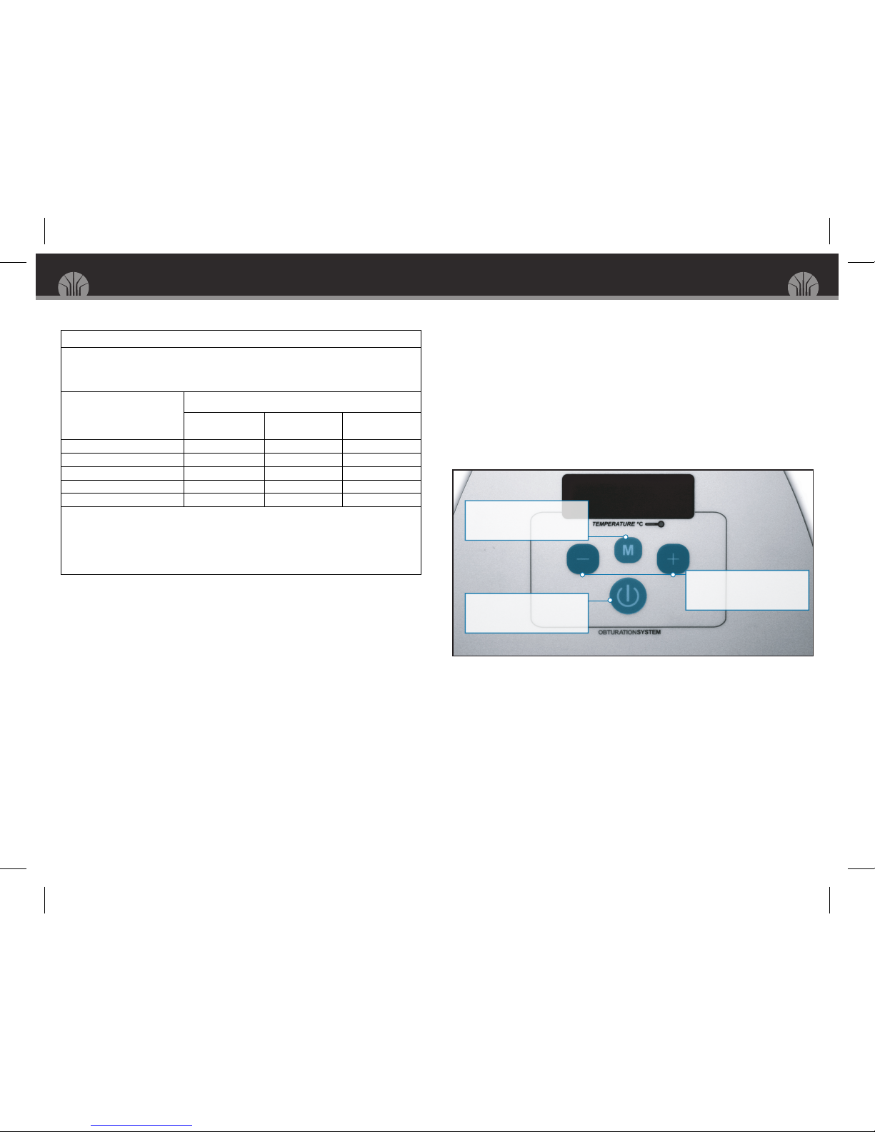
The Obtura III MAX utilizes push-button digital temperature controls for more accurate, reproducible settings,
and a memory function that stores up to 5 user-selectable temperature settings for your convenience.
TheObturaIII MAX complies with current Electromagnetic Compatibility standards (IEC 60601-1-2). Theuser should
ensure that any possible electromagneticinterference isnot present, as it could potentiallydamagethedevice or any
other electronicdevice in the vicinity.
Unpacking and Assembling
Check all packaging for signs of damage; report any damage with the shipping agent immediately, so that claims
will be honored in a timely way.
Save all packing materials in the event of an instrument move or shipping at a later date (also see our “Greener
Earth” commitment on the reverse side of customer introductory letter).
Remove the clear plastic introduction bag, main control unit, handpiece, handpiece stand (complete with stand
attachment spacer and screws), power supply box, bagged supplies and accessory tool kit. Check for loose items.
Unwrap the main control unit and place on a flat surface. Locate the unit so that by extending the cord you will
not pull the unit off the surface. The handpiece cable length is approximately 224 cm (88 in.).
Locate the handpiece stand and place it next to the main control unit. The stand provided for the handpiece can
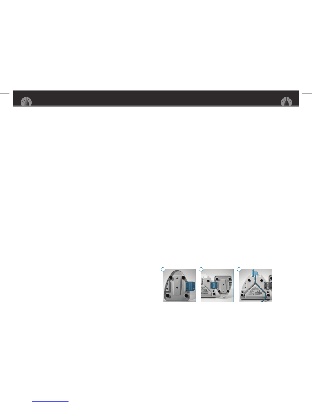
be attached to the Obtura III MAX (if desired) by the following means:
After determiningwhich sideyou want thestand placed on, simply remove the2 screws on the bottom of
--------the stand. After the screws are removed, hold theattachment platetothebottom of the stand, and re-attach
--------it tothedesired location soit hangs off theside(as shown in diagram A). Then attach the handpiecestand
--------and bracket tothemain control unit using the two remaining screws (seediagram B).
Plugthehandpiece cord connector intothe rear ofthe main control unit (note thealignment of the “red dot” at the
12 o’clock position, and a“click” to signifycomplete insertion). Should theuser require the cord toexit thefront
of the unit, invert theObtura III MAX on a smooth, soft surface and gently press the cableintothetracksprovided,
leavinga small loop ofcable from thehandpiece cord port to the beginningofthe track. The cablecan exit on the
left-front or the right-front (see diagram C), or from the rear (without use of thecabletracks).
Open the whitepower supply box and remove the power supply unit and receptacleblades. Choose the correct
blade tofit your electrical outlet and slideit on to the power supplyunit. Plug the power supply connector into
thepower supplyport at the rear of themain control unit; plug the power supply unit intoan electrical outlet. The
ObturaIII MAX screen will momentarily light up, indicating the version of installed firmware, and then turn off.
This only occurs when first connecting themain control unit to the electrical outlet.
UNPACKING AND ASSEMBLING 3
A B C
OPERATOR’SMANUAL HEATED GUTTA PERCHA SYSTEM
SECTION VI – Health Hazards
Routes of Entry: Skin and eye contact. Inhalation.
Signs and symptoms of exposure:
Skin contact: Repeated exposure may cause skin dryness or cracking
Eye contact: Irritating to eyes
Inhalation and Ingestion: Excessive inhalation of vapors can cause irritation of the respiratory tract,y
nausea, dizziness, or headache. Product has a low order of acute oral toxicity, but ingestion of large
quantities may cause nausea, vomiting, and gastrointestinal irritation. May cause injury if aspirated into lungs.
Medical conditions aggravated by exposure: Persons with pre-existing central nervous system (CNS) disease,
neurological conditions, skin disorders, chronic respiratory diseases, or impaired liver or kidney function should
avoid exposure.
SECTION VII – Emergency First Aid Procedures
Eyes: Check for and remove contact lenses. If irritation or redness develops, flush eyes with cool, clean, low
pressure water for at least 15 minutes. Hold eyelids apart to ensure complete irrigation of the eye and eyelid
tissue. Do not use eye ointment. Seek medical attention immediately.
Skin Contact: Remove contaminated shoes and clothing. Clean affected area thoroughly with mild soap and
water. Do not use ointments. Seek medical attention if irritation persists.
Inhalation: Immediately move victim to fresh air. If victim is not breathing, immediately begin rescue breathing.
If heart has stopped, immediately begin cardiopulmonary resuscitation (CPR). If breathing is difficult, seek
medical attention immediately.
Ingestion: DO NOT induce vomiting unless directed to do so by a medical personnel. Never give anything by
mouth to an unconscious person. If spontaneous vomiting is about to occur, place victim’s head below knees. If
victim is drowsy or unconscious, place on the left side with head down. Do not leave victim unattended. Seek
medical attention immediately.
SECTION VIII – Special Precautions, Spill/Leak Procedures, and Transportation
In case of spill: Small Spill and Leak, absorb with an inert material and dispose of properly. For Large spill and
leak, secure the area and control access. Dike far ahead of a liquid spill to ensure complete collection. Pick up
free liquid for disposal using absorbent pads, sand, or other inert non-combustible absorbent materials. Place into
appropriate waste containers for later disposal.
Waste disposal: Waste must be disposed of in accordance with federal, state, and local environmental control regulations.
Handling: DO NOT spray into or around ignition sources. After handling, always wash hands thoroughly with
soap and water. Use only with adequate ventilation. Avoid breathing vapors or spray mists.
Storage: Keep container in acool, well-ventilated area. Avoid all sources of ignition (spark or flame). Store below 120 °F.
Transportation: D.O.T. Ground – Not Regulated. IATA Air – Flammable Liquid, n.o.s., Hazard Class 3, UN1993,
Packing Group III
SECTION IX – Special Protection Information / Control Measures
Protective wear: Safety glasses and nitrile gloves
Ventilation: Provide exhaust ventilation or other engineering controls to keep the airborne concentrations of
vapors below their respective occupational exposure limits.
Respiratory Protection: Use organic vapor cartridge type respirator if ventilation is inadequate.
Work / Hygienic Practices: Wash thoroughly after handling. Have eye-wash facilities immediately available.
***IMPORTANT***
While seller believes that the information contained herein is accurate, such information is offered solely for its
customers’ consideration and verification under their specific use conditions. This information is not deemed a
warranty or representation of any kind for which seller assumes legal responsibility.
24-Hour Emergency #: (U.S.) (800) 535-5053 • (Outside U.S.) (352) 323-3500
14 MATERIAL DATA SAFETY SHEET

Operation
Operation of the ObturaIII MAX has been designed to be intuitive, however, to fully realize the extent of theinstrument
and itsmany features, please read this entire section.
There are four (4) tactile switches on the front of the ObturaIII MAX and an LCD display. The functions of the
four switches are: Power On/Off , Temperature Up, Temperature Down and Temperature Memory (as shown
in the“QuickStart Guide” section). When the ObturaIII MAX is activated, the3-digit display will indicate
the current operatingtemperature in degrees centigrade, and any memory presets desired. Description of each
button follows:
Press the Power On/Off button to activate the Obtura III MAX. The display will show the last used set-
------point temperature. After 5-seconds, theactual heater temperature will be displayed, heatingup tothe
------set-point. Press the Power button again to toggle off.
With theunit on, press the Temperature Up (+) button toincrease the set-point temperature in single degree
------increments. Press the Temperature Down (-) button to reduce the set-point temperature, also in one degree increments.
The Temperature Memory button retrieves preset memory set-points. A quick press of this button displays the
------letter “M” and the preset position number. Thetemperature associated with thememory settingisdisplayed on the
------three-digit display. To set theunit tothistemperature, no other action is required, and after 5 seconds, it will now
----- be thenew set-point temperature and will be indicated on theunit screen. To access another memory position,
------again press the Temperature Memory button todisplay thedesired memory setting, and again within 5-seconds,
------the unit will set tothenext positioned temperature.
To reset a memory location, press the Temperature Memory button until the preset position number you
------want to modify is shown. Then, within 5 seconds, adjust the preset temperature with the Temperature -------
------Up (+) and Temperature Down (-) buttons. The memory and the display are now set to the new temperature.
------After 5 more seconds, with no button pressed, the Obtura III MAX display will change from the previously
------set temperature to the new set-point temperature. Note: preset memories are saved even during power failure.
The Obtura III MAX requires approximately 120 secondstoheat from ambient room temperature of about 25°C, to
maximum operatingtemperature of 200°C.
For your convenience, the tablebelow can be used as a reference:
4OPERATION
Memory Number Factory Preset New Setting Date
M1 140°C
M2 150°C
M3 170°C
M4 180°C
M5 200°C
OPERATOR’SMANUAL HEATED GUTTA PERCHA SYSTEM
Material Safety Data Sheet
Obtura Cleaning Solution
Catalog Numbers: 822-609, 3069-01, 3069-01A, 823-703, 823-601, 823-600, 823-603, 35-114, 823-803
SECTION I – Manufacturer
Obtura Spartan
2260 Wendt Street
Algonquin, IL 60102
(800) 344-1321
SECTION II – Hazardous Ingredients / Identity
% by weight CASRN
40 – 60 % 64742-88-7
COMPONENT
Solvent Naphtha, (petroleum)
medium aliphatic
d-limonene 40 - 60 % 5989-27-5
SECTION III – Physical & Chemical Characteristics
Solubility: Less than 0.1%
Boiling Point: 157 °C @ 760 mmHg
0.80 – 0.82 @ 20°C
Vapor Density: 4.8
V.O.C Content: 100%, 810 g/L, 6.75#/gal
Evaporation Rate (Butyl Acetate = 1): 0.15
Appearance / Odor: Colorless Liquid with Orange Aroma
SECTION IV – Fire & Explosion Data
Flash Point: 40 °C (104 °F)
Flammable Limits in Air, % by Volume (Estimated): Lower: 0.7%, Upper: 6%
Extinguishing Media: Dry chemical, water spray, fog, or foam
Auto-ignition Temperature: Not Established
Special Fire Fighting Procedures; Unusual Fire and Explosion Hazards: Small Fire, Use Dry chemical powder.
Large Fire, use water spray, fog, or foam. Cool containing vessels with water jet in order to prevent pressure
build-up, auto-ignition, or explosions. Firefighters must use full bunker gear including NIOSH-approved positive
pressure self-contained breathing apparatus to protect against potential hazardous combustion or decomposition
products and oxygen deficiencies. Evacuate area and fight fire from a maximum distance or use unmanned hose
holders or monitor nozzles.
SECTION V – Physical Hazards (Reactivity Data)
Stability: Stable
Hazardous Polymerization: Will not occur
Hazardous Decomposition Products: Carbon Oxides (carbon monoxide and carbon dioxide) upon combustion.
Conditions and Materials to Avoid: Extremely reactive or incompatible with oxidizing agents.
2
2
O
Health
Fire
Reactivity
MATERIAL DATA SAFETY SHEET 13

Installing a Needle
To place the gutta percha where desired in the root canal, choose an applicator needle diameter best suited (20, 23 or
25-gauge). With the Obtura III MAX off and cool, remove the needle nut using the Multi-Tool; the needle nut should
remain on the Multi-Tool when unscrewed. Place the appropriate needle in the rear of the needle nut, so that the length of
the needle protrudes through and forward (diagram G). Re-attach the needle nut on to the heater thread using the Multi-
Tool, making sure not to cross-thread (diagram H). Tighten until snug (do not over tighten, but do not leave too loose).
Bending the Needle
In most situations, a straight applicator needle will not provideaccess to the root canal. UsingtheMulti-Tool, gently
bend theneedletoprovide a shape conducive to the procedure (see diagram I). Be careful not to bend too sharply as
kinks will result and gutta percha flowwill beblocked. For accessto difficult to reach root canals, simply loosen the
needlenut, rotate theneedletodesired position, and then re-tighten.
Loading Gutta Percha
WARNING: USING MORE THANONE STICK OF GUTTA PERCHA AT A TIME MAY DAMAGE THE SEAL.
DO NOT USE MORE THAN ONE PIECE AT A TIME.
Power on the ObturaIII MAXand wait for theheater to come up toyour desired temperature. Press the handpiece release
button on the top of theObturaIII MAX handpiece and withdraw the plunger shaft. Insert a guttapercha stickintothe
chamber via the opening just forward ofthe release button (see diagram J). Re-insert theplunger shaft until theplunger seal
engages the gutta percha pellet. Some resistance will be felt as thegutta perchaispushed forward totheheatingchamber.
Expressing Gutta Percha
Specifics totechnique will not be addressed here, but a few reminders and hints follow:
•When expressing gutta percha, do not “withdraw” the Obtura III MAX, but let the gutta percha fill “push” the
----------needle out of the canal. Pulling the needleout may cause voidsand require condensation or re-work.
•Take care when bending needles, as a kink will make it all but impossible to express material. Also, repeated
----------bending will cause needle weakening and subsequent breakage.
•Wait for the gutta percha to come up to full operating temperature before attempting to express; material that
----------is too cool will require much more pressure or may be impossibleto pass through asmall diameter applicator needle.
•Before beginning a procedure, express about 3 cm of gutta percha so that the up-to-temperature material will be
----------at the end of theneedle; the warm material will fill space more completely.
INSTALLING A NEEDLE 5
G
I
J
H
OPERATOR’SMANUAL HEATED GUTTA PERCHA SYSTEM
Factory Repair/Contact Us
Factory Service is available at Obtura Spartan. Please call the number below for technical support and
problem diagnosis.
ObturaSpartan
(800) 344-1321
www.obtura.com
It is necessary to acquire an RMA number before returning your unit. Failure to do this may result in longer repair
times and additional charges.
If you have spoken to the repair department and it is determined that the unit must be returned to the factory,
please be sure to pack carefully and appropriately. Use the original box and packaging (if possible), or a
minimum of 8 cm (3 in) impact-absorbing insulation in yournew box. Obtura Spartan will not be responsible for
damage due to improper packing or shipping. Insurance is optional andhighly recommended.
Note: Unauthorized repair will void all warranties. Authorized repair procedures must follow all safety
precautions. Be sure that the power supply connector is disconnected from the power supply port before
authorized repairs, and that safety glasses are worn at all times during the authorized repair procedures.
Replacement Parts
PN PNDescription Description
823-800
823-810
823-711
823-616
823-618
823-812
823-620
823-635
823-815
822-602
822-604
823-813
822-613
825-103
823-814
823-623
822-609
Obutra III MAX Complete System
Obtura III MAX Handpiece
Obtura Power Supply
Obtura Needle Nuts - Pack of 2
Obtura Plunger Seal Assembly
Obtura III MAX Plunger Shaft with Plunger Seal
Obtura Applicator Needles - 20 Gauge
Obtura Applicator Needles - 25 Gauge
Obtura III MAX Thermal Protectors - Pack of 4
Obtura Gutta Percha - Box of 100 Pieces
Obtura Flow 150 Gutta Percha - Box of 100 Pieces
Obtura III MAX Multi-Tool
Obtura Cleaning Brushes - Pack of 2
Obtura Heater Reamer Tool
Obtura III MAX Handpiece Bushing
Obtura Applicator Needles - 23 Gauge
Obtura Cleaning Kit - Bottle of Cleaning
Solution with 2 Brushes
12 FACTORY REPAIR/CONTACT US

6STERILIZATION INSTRUCTIONS
Sterilization Instructions
The Obtura Thermal Protectors are designed to provide patient protection from the elevated temperatures
of theheating chamber. Patient contact requires that the Thermal Protectors be sterilized between uses to
prevent cross-contamination issues.
Thermal Protector Sterilization Instructions
1.Turn off the unit and allow it to cool to room temperature.
2. Using the Obtura Multi-Tool, disengage the tab on the rear of the thermal protector.
3. Pull the Thermal Protector off the front of the handpiece.
4. Place the Thermal Protector in a cassette-style autoclave at 135°C for 10 minutes.
NOTE: The Applicator Needle on theObtura is not intended for multiple uses. It should be removed after
a single use and disposed of. Anew Applicator Needle shall be used for each procedure. Failure to change
the Applicator Needleincreases therisk of cross-contamination during aprocedure.
5. After replacingthe Applicator Needle, Reinstall the Thermal Protector by pressingit ontothe front of
the handpiece. Be careful of the Applicator Needle as it is capable of injuring your hand.
By steam sterilizingtheThermal Protector and using a new Applicator Needle every time, you are greatly
reducing the chance of any cross-contamination to your patients.
If you have any questions regardingthis or any other aspect of using the ObturaSystem, please call us at
1-800-344-1321.
Thank you,
ObturaSpartan
OPERATOR’SMANUAL HEATED GUTTA PERCHA SYSTEM
In the control unit, the data stream from the handpiece is read (and thetemperature interpreted) by a micro controller.
This builds display datafor theLCD and reads thetouch-panel. The processor also turns the heating element on and off
several hundred times per second tomaintain constant temperature. A“watchdog” processor performsself-diagnostics
for the system.
Power supply voltage never enterstheObtura III MAX, as the voltage isconverted to 12-volts DC via an external switch-
mode power supply. Selection and installation of the appropriate plug blade is all that isnecessary to configure theunit.
Low-voltage enters thecontrol unit case via a “standard” power supply connector.
Frequently Asked Questions
Q. How often should the unit be cleaned?
A. The Obtura III MAX should be cleaned at theend ofeach day or procedural session (see page 6).
Q. How often should the applicator needle be changed?
A. The applicator needlemust be changed after each patient operation and when damage isdetected or suspected. Thisis
----to ensure proper operation and toprevent the spread of infectious diseases.
Q. How often should the plunger seal be changed?
A. Observe seal for wear; replace if seal is torn or missing (see page 8).
Q. Why should I only use one pellet of gutta percha?
A. Critical lengths of the mechanical components of theObturaIII MAXhave been designed for asinglepiece of gutta
----percha; using more can cause excessive back pressure and damage (see page5).
Q. Is theObtura III MAX Handpiece Autoclavable?
A. No, the Obtura III MAX handpiece isnot autoclavable. It should be cleaned usinga BIREX-type solution. Onlythe
----thermal protectors are autoclavable, once removed from the handpiece.
Q. The handpiece trigger isnot working, how can I fix it?
A. Incorrect bushing installation can cause the trigger not to work. Make sure the bushingis installed with the small
----indicator line at the 12’ O’ Clock position at theback ofthehandpiece (see page8).
Q. Can I leave the needle nut loose so that it can be rotated duringuse?
A. No, the needle nut is not designed tobeused in this manner. Theneedle nut must always be tightened securely
---before extruding gutta percha (see page 5).
Q. How doI disconnect the ObturaIII MAX Handpiece Connector from thebase unit?
A. Squeeze the serrated section on thehandpiece cord connector (by thetriangle) and gently pull back. Connector does
----not turn (see page9).
Q. Can I use the Obtura III MAX if thedisplay is showing an Error Code?
A. No, your ObturaIII MAXunit should be evaluated and repaired if it isdisplaying an error codeon the screen (see page 9).
Q. Is there any way to reduce the force required to extrude guttapercha?
A. Yes, afew options exist. You may try toincrease the operatingtemperature toimprove the flow ability of our
---standard guttapercha. ObturaSpartan also sellsFlow150 gutta percha and Resinatepelletsthat may flow
---more easily than the standard guttapercha.
FREQUENTLY ASKED QUESTIONS (AND ANSWERS) 11
135
°
C

Error Codes
Handpiece Attachment/Detachment
To Attach: Hold the handpiece cord connector at the rear of the main control unit, facing the triangle indicator at the
12 O’Clock position (see diagram N). Plug in to the handpiece cord port when proper alignment is reached.
To Detach: Squeeze the serrated section on the handpiece cord connector (by the triangle) and gently pull back (see
diagram O). Connector does not turn.
Error Code Fault Remedy
S-1
S-2
H-1
H-2
H-3
B-1
P-1
Handpiece disconnected (communication failure)
Cannot reach Temp. in 255 sec
Heater Wire open
Heater Wire short
Thermocouple error
Internal control base failure
Power Supply fault
Heater fault – Contact factory for repair
Replace handpiece or contact factory for repair guidance
Not user-serviceable–Contact factory for repair
Replace power supply or contact factory for repair guidance
1) Verify fitment ofhandpiece connector
2) Remove and replace
3) Check cable for breaks or damage
4) Check connector for broken or bent pins
5) Contact factory for handpiece repair/replacement
N O
OPERATOR’SMANUAL HEATED GUTTA PERCHA SYSTEM
Theory of Operation
Theheating system ofthe ObturaIII MAXis a closed-loop design to ensure consistent temperatures and uniform gutta
percha flow. This meansthat thetemperature of the heater is read several hundred times per second and corrected (as
necessary) to insure accurate and consistent heating.
In the handpiece, the temperature ofthe heating chamber is detected by a thermocouple integrated into the heating
element and encapsulated with epoxy. The output from the thermocouple is converted by an analogue-to-digital
converter, and intoadigital stream for use by the main control unit.
Thehandpiece is composed of a two-piece heat-resistant composite body that encapsulates thetrigger assembly
, heater
system and plunger.
Guttapercha is placed intothetop of the handpiece shell and expressed via the plunger shaft assembly. Pressing the
handpiece trigger, which pushes the shaft via a spring-loaded pawl, moves the shaft forward. The heater assembly is
directly connected to thehandpiece shell, providing a straight through path for gutta percha, warming it in the process.
10 ERROR CODES
Maintenance
For best results, theObtura III MAX handpiece should be cleaned daily. Thisprevents build-up of excess guttapercha
within the heating chamber.
Regular Maintenance (Day to Day Cleaning)*
Tools you will need:
•Multi-Tool
•Cleaning brush and Cleaning solution
•Disposable cloth (napkin, gauze, etc.)
1. Prior to cleaning, ensure that your Obtura III MAX unit is turned off, fully cooled and unplugged.
2. Unlatch and remove the thermal protector usingtheMulti-Tool.
3. A) Usethe Multi-Tool to unscrew the needlenut from the heater thread.
B)Set aside the needlenut. Dispose of theneedle(for optimum performance, Obtura applicator needles
------should be used only once).
4. Extrude all remaininggutta percha by squeezingthehandpiece trigger. The guttapercha will come out in solid pellet form.
5. Push and hold the release button, removingtheplunger shaft from thehandpiece.
6. A) Inspect the plunger seal for guttapercha.
B) Ifguttapercha ispresent, dip thecleaning brush intothe cleaning solution, fully coating the brush.
C) Clean the plunger seal with the cleaningbrush in a backand forth motion until all visible guttaperchaiscleared.
7. A) Inspect the insideofthe handpiece shaft for any visible guttapercha.
B) Ifguttapercha ispresent, re-dip the cleaning brush intothe cleaning solution, fullycoatingthebrush.
C) Place the cleaningbrush insidethehandpiece shaft and clean in aback and forth motion until all visible
------guttapercha is cleared.
8. A) Reassemble all components in the reverse order from which they were detached.
B) Place the handpiece back on its cradle.
WARNING: AT NO POINT SHOULD ANY PART OF THE OBTURA III MAX HANDPIECE BE SUBMERGED
INTO THE CLEANINGSOLUTION.
NOTE:A)For optimal cleaning, useaBirex®-type solution to aid in disinfecting and deodorizing your Obtura III MAX unit.
B) Never spray the disinfectant solution directlyon tothe unit; always spray into adisposablecloth, then wipedown.
*The above regular maintenance cleaning instructions are also displayed on the provided laminatedcleaning
instruction card, which containsvisual diagrams for your convenience.
MAINTENANCE 7

Extended Maintenance
As Needed for:
•Repeated plunger seal failure
•The plunger shaft repeatedly gets stuck in handpiece
•The cleaning brush is ineffective in removing excess gutta percha from the handpiece shaft during normal cleaning
Tools you will need:
•Multi-Tool
•Cleaning brush and Cleaning solution
•Disposable cloth (napkin, gauze, etc.)
•Heater Reamer Tool*
1. Prior tocleaning, ensure that your Obtura III MAX unit is turned off and fully cooled.
2. Unlatch and remove thethermal protector using the Multi-Tool.
3. Use the Multi-Tool tounscrew theneedle nut from the heater thread. Set aside theneedle nut. Dispose of the needle
---(for optimum performance, Obturaapplicator needles should be used only once).
4. Turn the unit back on and allow it to reach full operating temperature (200˚) in order to loosen residual gutta percha.
5. Oncethe full operatingtemperature is reached, turn off the unit and unplug.
6. Immediately extrude all remaininggutta percha into a disposable cloth by squeezing the handpiece trigger.
---(WARNING: CONTENTS WILL BE EXTREMELY HOT!)
7. Push and hold the release button, removing the plunger shaft from the handpiece. Visually inspect the plunger seal
---to determineif a replacement isnecessary (example: metal threads at the tip of the plunger shaft are exposed or there
---is other obvious erosion).
8. Using the heater reamer tool, clean thehandpiece shaft in a back and forth motion until all visible gutta
---perchais cleared.
9. Dip thecleaning brush intothecleaningsolution, fully coating the brush. Clean the handpiece shaft with the cleaning
---brush in a back and forth motion until all excess gutta percha is cleared.
10. Reassemble all componentsin the reverse order from which they were detached. Place the handpiece back
-----on its cradle.
WARNING: AT NO POINT SHOULD ANY PART OF THE OBTURA III MAX HANDPIECE BE SUBMERGED
INTO THE CLEANING SOLUTION.
NOTE:A) For optimal cleaning, use a Birex®-type solution to aid in disinfecting and deodorizing your ObturaIII MAXunit.
B) Never spray thedisinfectant solution directly on totheunit; always spray intoa disposable cloth, then wipe down.
*The heater reamer tool should only be used as needed.
The Thermal Protectors must sterilized before use.
OPERATOR’SMANUAL HEATED GUTTA PERCHA SYSTEM
8MAINTENANCE
Handpiece Bushing
HandpieceBushingis susceptible to wear caused by the bushing misalignment. This causes thetrigger pawl towear
at the pawl engagement opening. Thebushingshould be aligned in the handpieceso that bushing rotation ceases. To
install the handpiece bushing, slide it in the opening at the rear ofthehandpiece (diagram K), and turn clockwiseuntil
resistance is felt. The handpiece bushing should be cleaned or replaced asneeded.
Plunger Shaft Assembly
Areas of inspection consist of theplunger seal and the plunger teeth. The plunger seal should be inspected for wear or
breakage. Gutta perchaexpressed through the handpiecewill give aquick and accurate indication of theplunger seal’s
condition. If excessive gutta perchapasses bythe seal, theplunger seal assembly should be replaced. The plunger teeth
should beinspected for wear or chipping. Theplunger shaft should be replaced ifplunger teeth are badly chipped or
slipping occursduringtesting. Theplunger shaft of the ObturaIII MAX should be checked for bending; if it will not roll
smoothly on a piece ofglass or flat tabletop (indicatinga bow or bend), it should be replaced, as theuse ofa bent shaft
maycausedamage to the heater bore.
Plunger Seal Assembly
To remove theplunger seal assembly, first locate theMulti-Tool’s small hex shapeopening(diagram L). Then heat theend ofthe
plunger shaft (alighter will work; please use precaution)tosoften the thread-locker. After the thread-locker softens, carefully
insert the plunger seal assemblywithin the hex shape opening, and unscrew the plunger seal assembly from theplunger shaft
(diagram M). To replace the assembly, thoroughly clean the end of the plunger, usingextra care, to be sure thethreadsare clean
and dry. Re-apply and tighten the plunger seal assembly using the Multi-Tool’s hex utility once again. Donot over-tighten.
Needle Nut
Theneedle nut may become filled with guttapercha, which will inhibit complete tighteningand thermal transfer from
theheater to the applicator needle. Theneedlenut threads can be cleaned with a1/4-28tap, but it’s usuallymore
efficient to replace it. Theneedle nuts can be collected and cleaned thoroughlyat a later datefor re-use. If the needle
nut does become filled with gutta percha, it may indicate that theneedle nut has been tightened insufficiently. Use the
Multi-Tool toassure proper fit.
Handpiece Cable Assembly
The handpiece cable should be thoroughly inspected at the handpiece entry point for brokenwires and cracks in the cable
housing (may be duetothe frequent bendingin this area). These signs are an intermittent problem where theunit will
work fineinitially, but when thehandpiece cable is bent, theunit stops heating altogether. Ifthese conditions exist, the
error codes on theObturaIII MAX display can diagnose them (see error codes chart on page 9).
K
L M
MAINTENANCE 9
Table of contents
Popular Medical Equipment manuals by other brands

OREX
OREX PcCR 1417 ACL4 installation manual

agiliti
agiliti NP Duo user manual

Fazzini
Fazzini ANEROID SPHYGMOMANOMETER Instructions for use

Custo Med
Custo Med custo screen 300 operating manual

Aseptico
Aseptico DTC 2 AEU-26 Operation and maintenance instruction manual

Direct Supply
Direct Supply ATLAS owner's manual