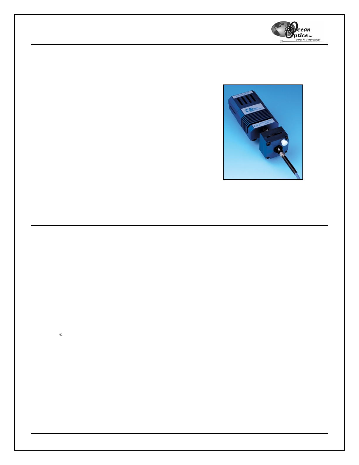
LS-1 Series Tungsten Halogen Light Sources
LS-1 Series Tungsten Halogen Light Sources 6
Installing the Blue Filter or Teflon Discs in the R-LS-1
The BG-34 filter and Teflon disc can be permanently installed into the LS-1 to further optimize your experiment.
The BG-34 filter amplifies the blue region in relation to the other regions in the spectrum, while the Teflon discs
diffuse the light emitted from the R-LS-1. A BG-34 transmission graph can be found at the end of this manual.
Before installing blue filter discs, Teflon discs, or light bulbs in the R-LS-1, you must first remove the R-LS-1 from
the rack it is installed in.
See the Removing the R-LS-1 from a Rack section before continuing.
Follow the instructions below to install the BG-34 blue filter or Teflon discs into the R-LS-1:
Note: This procedure involves opening the R-LS-1 light source. Before opening, ensure that the lamp has been
off long enough to allow the unit to cool and disconnect the power supply from the R-LS-1.
1. Make a note the location of the four Phillips screws on the bottom of the R-LS-1. You must return these
screws to this exact position when reconnecting the R-LS-1.
2. Loosen the four Phillips screws on the bottom of the R-LS-1. These screws hold the blue anodized bulb
housing in place on the R-LS-1 card.
3. Slide the R-LS-1 in place on the card until the recessed silver Allen screw is visible under the blue
anodized bulb housing on the bottom of the R-LS-1 card.
4. Use the Allen wrench included with the R-LS-1 to loosen the small silver screw. It is not necessary to
remove this screw completely.
5. Slide the silver lamp tube out of the blue anodized bulb housing.
6. Insert the BG-34 filter or Teflon disk you wish to install into the ½” counter bore on the inside of the blue
anodized bulb housing (where the silver lamp tube resides when the lamp is assembled). Ensure that the
disk lays flush against the bottom of the ½” counter bore.
7. Replace the silver lamp tube, ensuring that it fully inserted into the ½” counter bore.
8. Hold the silver lamp tube in place and re-insert the small silver screw that you loosened in Step 4. This
fastens the silver lamp tube in place.
9. Tighten the four Phillips screws on the bottom of the R-LS-1 card. Ensure that the black wire is still
connected to the rear of the silver lamp tube.
10. Connect the R-LS-1 as described in the Connecting the R-LS-1 section.
You have now properly installed the BG-34 or Teflon disc into the R-LS-1.
Using the Filter Slot on the R-LS-1
The 3 mm slot between the lamp and the fiber coupler can be used to hold filters or light blocks. You can place a
filter in the filter slot, but you must heed the following warnings:
• Filters must be 3 mm thick or less
• Filters should not be plastic, as they may melt from the intense heat generated by the lamp
• Filters should not be flammable materials, as they may ignite due to the intense lamp heat
• Filters cannot be clamped in place, as there is no filter locking mechanism built into the lamp
Artisan Technology Group - Quality Instrumentation ... Guaranteed | (888) 88-SOURCE | www.artisantg.com