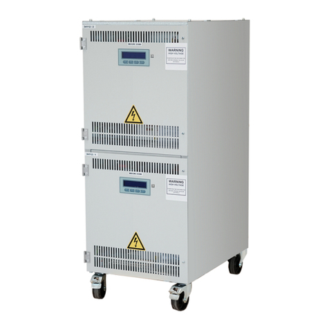
OCEM DIAM3200 IGBT User manual

Use and Maintenance Manual
ocem
EN
3f5fce93-e8c9-4dd7-bbfa-15aabef6433c
Stackable
Constant
Current
Regulator
(IGBT)
UT-MT-0938_1.0_30-03-2023 (EN)

Contact us
Editions
Revision Date Notes
1.0 30-03-2023 First publication
UT-MT-0938_1.0_30-03-2023 (EN) | These specications may be subject to change.
© Copyright 2021 OCEM Aireld Technology (Italia) | All rights reserved.
OCEM Aireld Technology, and any other name/brand associated with products OCEM Aireld Technology mentioned or indicated in this document,
are trademarks or registered by OCEM Aireld Technology. The rights of third parties on each registered trade mark mentioned in this document
are the property of their respective owners.
The copyrights of this manual are the property of OCEM Aireld Technology. The instructions, drawings, tables and other contained in this manual
are of a reserved technical nature and cannot be reproduced and/or disclosed, whether in full or in part, without prior authorization of the
Manufacturer. The reproduction of this manual is allowed for the sole purpose of making one backup copy. OCEM Aireld Technologyreserves,
under the law, the property of this manual, by prohibiting the transfer to third parties and/or the unauthorised reproduction.

UT-MT-0938_1.0_30-03-2023 (EN)
Use and Maintenance Manual
DIAM3200
3
1 GENERAL INFORMATION
1.1 Safety information 5
1.2 EC directive 5
1.3 Package content 6
1.4 Manual reference guide 7
1.5 Safety instructions 7
1.6 Safety symbols 8
1.7 Denitionofoperator 8
1.8 Limited warranty 9
1.9 CE marking 10
1.10 Condentiality,industrialpropertyrights 10
1.11 Disposal 10
1.12 Articleidentication 10
2 FIXTURE DESCRIPTION
2.1 Generalcharacteristics 11
2.2 Operatingprinciple 12
2.3 Reference standards 13
2.4 Nb.ofsteps 13
2.5 Supplyvoltage 14
2.6 Nominalpower 14
2.7 Wired remote control 14
2.8 Communication network 14
2.9 Protection systems 14
2.10 CUT-OUToutputdisconnector 14
2.11 Product Code 15
2.12 Behaviourincaseoffault 16
2.13 Wiring 17
3 INSTALLATION
3.1 Constant current regulator 19
3.2 Handlingandpositioningofthedevice 20
3.3 Preliminarychecks 21
3.4 Connectiontothepowersupply 22
3.5 Connectionoftheseriescircuit 23
3.6 Remotecontrolconguration 24
3.7 External circuit selector interlock 25
3.8 Testsandchecks 26

UT-MT-0938_1.0_30-03-2023 (EN)
Use and Maintenance Manual
DIAM3200
4
4 ADJUSTMENTS AND MAINTENANCE
4.1 Preliminaryoperations 29
4.2 Selectionoftheoperationmode 30
4.3 Navigationmap 31
4.4 Local monitoring 32
4.5 Warning,faultandalarmmessages 33
4.6 Troubleshooting 34
4.7 Accesstotheparameters 35
4.8 Editparameters 36
4.9 Softwarecongurationutility 41
4.10 Scheduledmaintenance 42
4.11 CorrectiveMaintenance-ComponentIdentication 43
4.12 Troubleshooting 45
4.13 Spareparts 52

GENERAL INFORMATION
UT-MT-0938_1.0_30-03-2023 (EN)
Use and Maintenance Manual
DIAM3200
5
1 GENERAL INFORMATION
1.1 Safety information
HIGH VOLTAGE - RISK OF DEATH
This equipment is normally used in systems using dangerous and lethal levels of voltage.
Usetheutmostcarewhenoperatingandmaintainingtheequipmentandtherelatedcircuits.
Consulttheapplicablerulesandregulationsonsafetyandworkprecautions:
●IEC61820,IEC61821
●FAA AC 150/5340-26
Always operate in compliance with all relevant standards and regulations in force in the country in which the
installationandoperationofthedeviceiscarriedout.
Installationandcommissioningofthedevicemayonlybecarriedoutbyqualiedpersonnelwhoareadequately
trainedonthefeaturesandtheuseofthedevice.
Stay away from potentially active parts.
Disconnecttheenergysourcesbeforeperformingoperationsonthedevice.Allowadequatedischargingtimefor
anyresidualenergybeforeaccessingthedevice.Useasuitablemeasuringinstrumenttocheckforresidualvoltage
beforecomingintocontactwithpotentiallyactiveparts.
Access the internal sides of the device only in cases of absolute necessity, such as
maintenance or repairs.
Wait until the device is completely de-energised before opening the device or removing the
panel for maintenance.
All personnel working on the device and its associated circuits must be qualied and trained
in rst aid and cardiopulmonary resuscitation (CPR) techniques.
1.2 EC directive
ThisdevicecomplieswiththerequirementsoftheECDirectives:
●2014/30/EUwithregardtoelectromagneticcompatibility
●2014/35/EUwithregardtolowvoltagedevices
The information in this document is for information purposes only and cannot be considered
a substitute for the declaration of conformity signed and issued by the Manufacturer or of
the certicates accompanying the product.

GENERAL INFORMATION
UT-MT-0938_1.0_30-03-2023 (EN)
Use and Maintenance Manual
DIAM3200
6
The CCRs DIAM3200 of OCEMAireld Technology are optimized static power supplies, controlled by IGBTs
(insulatedgatebipolartransistors),designedtomaintainaconstantoutputcurrent,independentofloadorpower
supplyuctuations.
Theoutputcurrentremainsconstantwithanaccuracyof100mAformainsvoltageuctuations±10%andwithall
loadsbetween0and100%andupto30%oftransformerswithopensecondary.
Thankstoitsuniquepowerarchitecture,theCCRsDIAM3200ofOCEMAireldTechnologyintroducenodistortion
ordegradationofthepowerfactor,whichremainsthatoftheload.Theharmoniccontentreectedonthesupply
networkisthereforeparticularlylow,overtheentireoutputcurrentrangeandforanyload.
Noadaptationtotheloadviasocketsisnecessary.ThedigitalprocessingcapabilityoftheDSPprocessorallows
ittobeadaptedtoanytypeofload:LEDxtures,halogenxtures,electronicconvertersorcombinedsystems.
TheCCRsDIAM3200ofOCEMAireldTechnologyperformanautomaticcalibrationthatavoidsanyanalogue
adjustmentduringmaintenance.AsimpleandintuitiveHMIuserinterfaceallowscleardisplayofalarmindications,
oftheCCRstatusandofallrelevantparameters.
Thesedevicesarespeciallydesignedforsupplyingairportvisualaids,incompliancewithallinternationalstandards.
Thedeviceisdesignedincompliancewith:
●ICAOAirportDesignManual,Part5;
●IEC61822(CCR),61821(Maintenance).
Immediately check for visible damages of the device and of the containing parts. Carefully
unpack the device and check for visible damages.
Store all the components in the original packaging until the time of installation.
Take care not to damage sheet metal parts, cables and internal components.
The device described in this manual is designed to power series circuits intended for airport
lighting of runways, taxiways and aircraft aprons.
1.3 Package content

GENERAL INFORMATION
UT-MT-0938_1.0_30-03-2023 (EN)
Use and Maintenance Manual
DIAM3200
7
1.4 Manual reference guide
Thisdocumentcontainsalltheinformationrelatedtotheequipmentanddescribestheprocedurestofollowduring
theinstallationoftheproductandduringordinarymaintenance.Thedocumentisindentedforalloperatorsthat
mustinterveneontheequipment.
This document does not replace in any manner applicable laws, rules or regulations, included the
standards FAA and ICAO.
Theprecautionsprovidedinthemanualarealwaysprecededbyasymbolasillustratedbelow:
Indicates the warnings, the notes, the suggestions and other points on which is intended to
draw the attention of the reader.
Indicates the operations to be carried out mandatorily or the information which should be
carefully read to avoid possible risks.
Indicates particular risks connected with the power supply. It reports the operations to be
carried out mandatorily or the information which should be carefully read to avoid possible
risks.
Theseprecautionssafeguardthepersonalsecurityofeveryonewhoworkonand/orareinproximityoftheequipment
andoftherelativesupplycircuits.
The failure to comply with the instructions (in particular those preceded by danger, warning, caution
precautions) can cause serious injury or death.
1.5 Safety instructions
CAREFULLY READ THIS DOCUMENT.
The improper use of the equipment or the failure to comply all the precautions indicated
implies life danger and serious injury to persons and damages to things.
HAZARD OF ELECTRICAL SHOCK, EXPLOSION OR ELECTRIC ARC
Carefully read the enclosed documentation before installing or starting to use the equipment.
Do not install the equipment until the completion of all construction works required to carry
out the work.
DO NOT OPERATE ON POWERED CIRCUITS
Do not carry out any operation on powered circuits.
Beforeeveryaccess,inspectionorinterventionontheequipment,ensuretohaveswitchedothe
equipmentbyopeningthemainpowerswitchandbyremovingthesupplyfromtheunit(openthe
powerswitchatthebeginningofthelineorswitchotheconstantcurrentregulator).
The failure to comply all the precautions indicated implies life danger and serious injury to
persons.

GENERAL INFORMATION
UT-MT-0938_1.0_30-03-2023 (EN)
Use and Maintenance Manual
DIAM3200
8
1.6 Safety symbols
Thesymbolsillustratedinthefollowingtableareusedintheuserandmaintenancemanualandonthedevice.
Thesesymbolsindicatetheexistenceofanydangeroussituations,toindicateobligationsandprohibitionsinrelation
tothesituationsthatmayrepresentanhazardfortheoperatororindicatethebehaviourtoadopttominimizethe
riskfortheoperator.
Warning signs Prohibition and obligation signs
W001 | General warning sign P001|Generalprohibitionsign
W004 | Laser beam M001 | General mandatory sign
W005|Non-ionizingradiation M002 | Refer to instruction manual/
booklet
W006|Magneticeld M005|Connectanearthterminaltothe
ground
W012 | Electricity M009|Wearprotectivegloves
W017 | Hot surface M015|Wearhighvisibilityclothing
W027|Opticalradiation M021 | Disconnect before carrying out
maintenanceorrepair
1.7 Denition of operator
Alloperationsondevicesandonitsinternalpartsmustbeperformedbyprofessionalsta,properlyformedand
awareoftherisksconnectedwiththepowersupplyandtotheuseoflowandhighvoltagecircuits.
Take all the precautions in compliance with the safety standards for the work carried out on
electrical installations and however for the works carried out using electrical installations or
in buer zones of the installations and of the electrical devices.
Alloperationsonequipmentsandonitsinternalpartsmustbeperformedbyprofessionalsta,properlytrained
forCardioPulmonaryResuscitation(CPR)techniques.
Never operate on devices if there is not at least another operator properly trained for CPR
techniques.
CheckthatOperatorsdonotoperateoutsidetheirownspeciceldsofcompetenceandresponsibility.OCEM
AireldTechnologydeclinesanyandallliabilityarisingfromwrongoperationscarriedoutbyuntrainedpersonnel
intheuseofthedevices,orderivingfromthenoncomplianceofgeneralsafetystandards.

GENERAL INFORMATION
UT-MT-0938_1.0_30-03-2023 (EN)
Use and Maintenance Manual
DIAM3200
9
1.8 Limited warranty
OCEMAireldTechnologyassuresthatalltheDIAM3200productsmarketedarefreeofmanufacturingdefects
atthetimeofshipment.Thislimitedwarrantywillbevalidfortheperiodindicatedinthesalesagreement.THIS
LIMITEDWARRANTYIMMEDIATELYDECAYSIFTHEPRODUCTISUSEDFORPURPOSESOTHERTHAN
ORIGINALLYINTENDED.
ThislimitedwarrantyisprovidedbyOCEMAireldTechnologytotheoriginalpurchaserofDIAM3200productsasidentiedby
thedocumentsissuedatthetimeofpurchase.Thislimitedwarrantycanbetransferredtothesubsequentpurchasersofthe
Product,onlyonconditionthatthisProductisresoldasNEWandwiththeoriginalpackaging.
Each change and/or tampering made to the product immediately terminates the warranty. OCEM
Aireld Technology cannot be held responsible for any damage to items or persons deriving
from the failure to comply with instructions relating to installation, use and maintenance of
the product, and to the installation and storage environmental conditions stipulated by the
Manufacturer or by applicable rules regarding electrical devices and systems.
Incaseofpotentialdefectsornon-usabilityoftheGoodssupplied,theapplicablewarrantythatexcludesanyotherlegalwarranty
andagreement-appliestothedefectsofmaterials,inthedesign,and/orintheinstallationoftheGoodssupplied.Thewarranty
consists,dependingontheSupplier,intherepairorreplacement,attheexpenseoftheSupplier,ofeachfaultycomponentor
malfunctioningcomponentfromthebeginning,butisnotextendedtodamagesarisingfromnegligenceorwear.
Thiswarrantylastsforatleast12monthsafterthedateonwhichthereceivedGoodsareputintoservice,butwillnotinany
caseexceed24monthsfromtheshippingdate.
FAA
For FAA certied products this warranty lasts for at least 4 years after the date on which
the received Goods are put into service, but will not in any case exceed 5 years from the
shipping date.
TheSupplierundertakestorepairorreplacethecomponentsintheshortestpossibletimewithoutprejudicetothefactthatfor
thesocalledcommercialcomponentsandmoregenerallyforthecomponentssuppliedbythird-partymanufacturers,willonly
beappliedthetermsoftherespectiveoriginalmanufacturer'swarranties.
ThewarrantyabsolvesfromallliabilitytheSupplieranddoesnotapplytothedamageofanykind,causedby:improperuse
bytheCustomerorbytheCustomer’ssta,useofinadequatematerials,orincorrectorinsucienttreatments;installation
ofequipmentsorsparepartsnotapprovedbytheSupplier;installationandoperatingworkingoftheGoodsreceivedwithout
followingtheindicationsandtheinstructionsprovidedbytheSupplier’sTechnicalsta;improperorexcessiveuse,insucient
maintenance,and/orworksnotcarriedoutincompliancewiththeinformationprovidedintheuseandmaintenanceinstructions;
anyotherreasonnotattributabletotheSupplier.TheCustomermustshoulder,atitsowncostandemployingitsownsta,
withoutinvolvingtheSupplier,thoserepairsthatonthebaseoftheSupplier’sopinionareconsideredcompliantatamoderate
leveloftechnicalknow-how.
TheCustomermust,underpenaltyofexpiration,communicatethecomplaintconcerningthedefectorthenon-compliancetothe
Supplierwithin 8 days from the date of discovery of the defect,andmustsendawrittenrequesttoactivatetheintervention
underwarranty.Theinterventionrequestunderwarrantymustbesentto:
OCEM Aireld Technology | via della Solidarietà, 2/1 | 40056 Valsamoggia BO (Italia)
TheCustomermustbearthetravelandaccommodationcostsbornebythetechnicalstaoftheSupplierthatmust
completeontheinstallationsiteanyinterventionassociatedwiththeguarantee.
Thewarrantyexcludesanyotherdamage,includedthoseresultingfromeconomiclossandfromlowproduction
capacity;direct,indirectorconsequentialdamages;andtheContracttermination.
TheSupplierisnotinanymannerresponsibleforanyothercompensationorindemnity,includingdamagederived
frommissedorreducedproduction,fromthelossofchance,fromthemissedorreducedprot,fromthelossof
contracts,impossibilityofuseoringeneralthepartialuse,inadditiontoindirectand/orconsequentialdamages.

GENERAL INFORMATION
UT-MT-0938_1.0_30-03-2023 (EN)
Use and Maintenance Manual
DIAM3200
10
1.9 CE marking
ThisequipmentcomplieswiththerequirementsofEuropeanlegislationfortheCEmarking.The
usershouldcarefullyreadthisdocumentandrespectalltherequirementsquoted.
ThisequipmentmeettherequirementsinrelationtohealthandsafetyofthemainECdirectives,andinparticular
oftheEMCDirectiveonelectromagneticcompatibility(2014/30/EU)andoftheLVDirectiverelatingtoelectrical
equipmentdesignedforusewithincertainvoltagelimits(2014/35/EU).
1.10 Condentiality, industrial property rights
TheCustomerneedstoadoptthemaximumcondentialitywithrespecttoalltheinformationoftechnicalnature
(including,bywayofexampleandnotexhaustively,plans,programmes,documentation,formulas,recipes,setting
andcorrespondence)receivedbytheSupplierorinanycaseassimilatedorgainedduringtheconclusionofthe
Contract of sale.
Anyrightregardingintellectualandindustrialpropertyconnectedtoequipmentandtoanyotherelementincluded
inthesuppliedGoodsasindicatedintheContractremainexclusivepropertyoftheSupplier.
1.11 Disposal
Attheendofuse,theusermustconferallthewasteinsuitabledierentiatedwastecollectioncentres.
ItistheresponsibilityoftheuserthecorrectdisposaloftheequipmentinaccordancewiththeWEEE
Directiveandwiththerespectivenationallawsinforceatthetimeofdisposal.Theseequipments
mustneverbedisposedofinthehouseholdwaste.
1.12 Article identication
Oneachequipmentthereisanidenticationplateofthearticle,wherethearticlecodeisreported;ontheplate
thereareadditionaldata:thenameofthemodel,employmentsoruse,powersupplyfeatures,anytrademarks
and/ormarksthatattesttheagreementoftheequipmenttospecicregulationsorlegislations.

DESCRIPTION
UT-MT-0938_1.0_30-03-2023 (EN)
Use and Maintenance Manual
DIAM3200
11
2 FIXTURE DESCRIPTION
2.1 General characteristics
TheDIAM3200constantcurrentregulatorsaredesignedforthepurposeofpoweringseriescircuitsforluminous
xturesofairportareas:runways,taxiwaysandaircraftaprons.
TheDIAM3200constantcurrentregulators(URCC)areoptimizedstaticpowersupplies,whosecontrolisensured
byinsulatedgatebipolartransistors(IGBT),capableofmaintainingconstanttheoutputstepsindependentlyfrom
theloaductuationsandthesupplyvoltage.
TheDIAM3200constantcurrentregulatorsarestackable(max.3units)tooptimizethespacetheyoccupyonthe
ground.
TheDIAM3200constantcurrentregulatorsarecompliantwiththerules:
IEC61822,Edition2.0
AENADIN/DNYM/PPT/002-05/13
The DIAM3200 constant current regulators described in this manual have been designed to
be installed on the levelled oor with adequate atness and strength characteristics.
The normal installation condition is a xed, stable and non-slip oor, free of protuberances,
hollows or inclined planes, designed and constructed with characteristics suitable to the
actual operating conditions.
The positioning of the unit must guarantee easy access to complete use and maintenance
operations.
The supply circuits, of suitable technical specications, can be positioned within pipes, ducts
or cable trays that comply with the applicable regulations in force.
In the same conduit, without separations, no conductors referring to dierent services must
be laid (this prohibition is extended to all connecting lines, even if the conductors operate
at the same operating voltage).

DESCRIPTION
UT-MT-0938_1.0_30-03-2023 (EN)
Use and Maintenance Manual
DIAM3200
12
2.2 Operating principle
Thecontrolandmanagementsystemofthedeviceisscheduledtomanagetheoperationoftheconstantcurrent
regulatorautomatically.Theunitalsoprovidesthepossibilityofadvancedfunctions,whichcanbeactivatedbythe
userifrequired(Wig-Wagmodeand4-20mAmode).
Whenabrightnesslevelisselected,thesystemactivatesthemaincontactorandadjuststhebipolartransistorsto
supplytheoutputseriescircuitwithacurrentvalueinaccordancewiththesetvalue.
Thedevicecontinuouslymeasurestheloopcurrent(viaaHalleectsensor),whichiscomparedwiththesetvalue.
Thedetectedrejectionisusedtocorrecttheoperatingparametersviaadigitalregulator.
Thedischargersontheoutputlineofthedevice(OLA)protectthedevicefromanyovervoltagesinthecircuit.
Theburntlampsdetector(LFD)allowsthedetectionofthepresenceofburntlampsontheseriescircuit.Ifused,
theLFDfunctionmustbeproperlyconguredandcalibratedontheeld.
Optionaldevicesperformcontrolandmonitoringoftheoperatingparameters,disconnectionmanoeuvresofthe
outputcircuittotheload,andinputovervoltageprotection,simplifyingtheoperationandfunctioningofthedevice:
●Aninsulationmonitoringsystem(EFD)allowscontinuousanalysisoftheresistancevaluebetweentheseries
circuitandearth,signallingtheexceedingofthepre-alarmandalarmthresholds.
●Anoutputdisconnectiondevice(CUT-OUT)simpliesthemaintenanceontheHVside:unitsequippedwith
thedisconnectiondevicecanbeservicedwithouttheneedtodisconnecttheseriescircuitterminalsand
theearthconnection.
●Inputdischarger(ILA)systemtoprotectagainstovervoltagesontheunit'ssupplylineofthedevice.
Inadditiontolocalcontrol,theconstantcurrentregulatorcanalsobecontrolledremotelythroughsuitableconnection
interfaces.Supervisionoftheconstantcurrentregulatormanagementsystemcanbedonethroughtheintegrated
displayandkeypad,orthroughtheAlizesoftwareinterface(usinganexternalPCconnectedviaUSBcabletothe
controller).
Bymeansoftheoptionalintegratedoutputcircuitselector(ICS),itispossibletoselectwhichportionoftheseries
circuittopower,inadditiontothesetcurrentlevel.

DESCRIPTION
UT-MT-0938_1.0_30-03-2023 (EN)
Use and Maintenance Manual
DIAM3200
13
2.3 Reference standards
Theconstantcurrentregulatorsaremanufacturedinaccordancewiththefollowingstandard:
●IEC61822,Edition2.0:Electricalinstallationsforlightingandsignallinginairportsandheliports-Constant
current regulator.
●AENADIN/DNYM/PPT/002-05/13:Technicalspecicationsforconstantintensitycontrollers.
2.4 Nb. of steps
Theconstantcurrentregulatorscanbeequippedwithanumberofstepsvaryingfrom1to8,eachcongurablein
therange1.8-6.6A,tomeetdierentend-userrequirements.
AccordingtoIEC61822,thenominaloutputcurrentrangeis:
●Type1:from4.8to6.6A
●Type2:from2.8to6.6A
The table provides the normalised CCR pre-settings. These settings can be modied in accordance with the
requirementsofanairport.
Type Nb. of steps CCR
1
B3 6.6 A
B2 5.5 A
B1 4.8 A
2
B5 6.6 A
B4 5.2 A
B3 4.1 A
B2 3.4 A
B1 2.8 A
Thetoleranceis±0.1Aforeachadjustmentwithinthenominaloutputcurrentrange.
The constant current regulator can supply a low-current heating brightness level (preferably
1.8 A), which is used to remove condensation from inside the xtures without switching on
the lamps.
The symbol for the local setting is B0.

DESCRIPTION
UT-MT-0938_1.0_30-03-2023 (EN)
Use and Maintenance Manual
DIAM3200
14
2.5 Supply voltage
Theconstantcurrentregulatorscanbesuppliedwithdierentvoltagelevels,dependingonthenetworkvalues.
Thesingle-phasepowersupplycanbechosenfromthefollowingvalues:220,230,240VAC[±10%(IEC),50/60Hz].
Thetwo-phasepowersupplycanbechosenfromthefollowingvalues:380,400o415VAC[±10%(IEC),50/60Hz].
Attention:Thesupplyvoltagevaluechosenwhenorderingcannotbechanged.
2.6 Nominal power
Theconstantcurrentregulatorsprovideamaximumoutputvoltagethatcanbeselectedaccordingtorequirements:
●2,5kVA
●5,0kVA
●6,5kVA
Attention:Thenominalpowervaluechosenwhenorderingcannotbechanged.
2.7 Wired remote control
Theconstantcurrentregulatorscanbecongured to be controlled andmonitored through dry contacts(relay
125VAC/2Aor125VDC/2Aforresistiveloads)andbyaninternalorexternalvoltage(from20to60VDC,positiveor
negative)orthroughwiredconnector(32PIN).
2.8 Communication network
Theconstantcurrentregulatorscanbeequippedwithdierentcommunicationinterfaces,dependingonrequirements.
OneormoreRJ45orD-Sub9-pin(M/F)doorscanbeprovidedonthefrontpaneltoprovideconnectivitythrough
themainstandards:
●RS485:serialcommunicationstandardEIA.
●LonTalk:controlprotocoldenedbythestandardISO/IEC14908.1
●Ethernet:networktechnologyforcommunicationviaLAN(Modbus/TCP).
2.9 Protection systems
Dependingoninstallationrequirements,theconstantcurrentregulatorscanbeequippedwithoptionalprotective
devicesinadditiontothethermal-magneticprotectionofthepowersupplyprovidedasstandard:
●Overvoltagedischargerontheinputline.
●Earthfaultdetectoroftheseriescircuit.
2.10 CUT-OUT output disconnector
TheinstallationofanoptionalCUT-OUTdisconnectorisausefultoolformaintenanceoperationsontheseries
circuit.ThemainfunctionofthedeviceistoeasilyconnectthepolesHV1andHV2oftheseriescircuittoearth
withoutneedforrewiringoperations.UsingtheCUT-OUTdisconnectitisalsopossibletoperformaloopimpedance
measurement.

DESCRIPTION
UT-MT-0938_1.0_30-03-2023 (EN)
Use and Maintenance Manual
DIAM3200
15
2.11 Product Code
example: D32 - IEC 5 - 40 02 - F 66A - ICS2 - S2 - ...
Reference standards1:
IEC
AEN
=IEC(61822,Edition2.0)( )
=AENA(DIN/DNYM/PPT/002-05/13)( )
Nb. of steps (brightness - from 1,8 to 6,6 A):
from 1 =1nb.ofsteps to
8
=8nb.ofsteps
Supply voltage:
22
23
24
=220VAC
=230VAC
=240VAC
38
40
41
=380VAC
=400VAC
=415VAC
Nominal power:
02
05
06
=2,5kVA
=5,0kVA
=6,5kVA
(Wired) remote control:
0
E
F
I
=notpresent( )
=Drycontacts(auxiliaryinternalsupplyVDC)( )
=Drycontacts(auxiliaryexternalsupplyVDC)( )
= 32 Pins terminal ( )
Communication network (default: 1):
1
2
3
4
= RS485 (x1)
= RS485 (x2)
= LonTalk (x1)
=Ethernet(x1)
5
6
7
8
=RS485+Ethernet
=Ethernet(x2)
= RS485 + LonTalk
=LonTalk+Ethernet
Protection systems (sum of the gures):
1
2
4
=InputdischargerILA
=Thermal-magneticcircuitbreakerCB(standard)
=EarthfaultdetectorEFD
CUT-OUT output disconnector:
0
A
D
= None ( )
=DisconnectorSIMALT2(withjumper,3positions)( )
=DisconnectorSCC(withhandle,3positions-ontheback)( )
Options2:
ICSx =SelectorICSwitxoutput(max.6)3
Stacked setting up
S2
S3
=2CCR-ICSpossible(connectedtolowerCCR)
=3CCR-ICSnotpossible
Particular equipments4:
DTxxxx =Specicationsprojectidenticationcode
1Always check the compatibility of the options with the selected reference standard: ( ) available only for D32‑IEC version..., ( ) available only for D32‑AEN
version... ;
2Anyadditionalcodesidentifytheoptionsintegratedinthedevice(ifnooptionisavailable,thiseldisabsent);
3The Selector ICS is compatible only with single CCR or with stacked setting up S2;
4AnycodeDTxxxxisassignedbythemanufacturertoidentifyanydesignspecicationsimplementedinthedevice(ifnoparticularequipmentisavailable,this
eldisabsent).
Inthe exampleD32 -IEC5-4002-F66A-ICS2-S2: CCRmodule made upof 2 unitsmodel DIAM3200(equal to
eachother).TheCCRsarecompliantIEC61822,5steps.Supplyvoltage400VAC,nominalpower2.5kVA.Wired
remotecontrolthroughstandarddrycontacts(withauxiliaryexternalsupplyVDC).Ethernetcommunicationnetwork
(2doors).Equippedwiththermal-magneticcircuitbreakerCB(standard)andearthfaultdetector(EFD).CUT-OUT
disconnectorSIMALT2typewith3positionsjumper.2waysintegratedcircuitselectorICS(connectedtolowerCCR).

DESCRIPTION
UT-MT-0938_1.0_30-03-2023 (EN)
Use and Maintenance Manual
DIAM3200
16
2.12 Behaviour in case of fault
Iftheunitdetectsafaultoranerror,thecontrolsystemappliescorrectionsandinformstheoperatorthrougha
messageonthedisplay.Thepossibletypesofwarningare:
●WARNING:theconstantcurrentregulatorcontinuesnormaloperationbutalertstheoperatorthataproblem
ispresent(thisisthecasewithEFDorLFDfault).
●ALARM:theconstantcurrentregulatorisunabletocontinuenormaloperationandinterruptsthecurrent
supplyduetoaninternalfault(e.g.alarmofoneoftheovercurrentthresholdlevels)oranexternalfault
(e.g.opencircuit).
When a fault occurs, prompt action must be taken to identify the cause of the fault and
eliminate the problem.
The system can only be reset by means of a manual reset (STOP key).
The unit preserves the memory of messages detected during operation even in the event of
the supply voltage. When switching the unit back on, proceed to resolution and restoration
of all messages in the memory.
2.12.1 Input voltage monitoring
TheinputvoltagemonitoringsystemanalysesandevaluateswhetherthepowersupplyvalueUiallowsthedevice
tofunctionproperly.WhentheinputvoltagevaluegoesoutoftheratedinputvoltageoperatingrangeUin(-15%
+20%)andremainsoutsidetherangeforacertainperiodoftime,thesysteminterruptsthepowersupplyandthe
unit goes into alarm.
Inthecaseofovervoltages:
●Ui>120%Uin:ifthevoltagevaluerisesabovethepre-alarmthreshold,theunitcontinuestooperatefora
maximumperiodof60seconds,afterwhichthesystemshutsdownandgoesintoalarmstatus.
●Ui>130%Uin:assoonastheinputvoltagevaluerisesabovethelimitthreshold,thesystemshutsdown
and goes into alarm status.
Inthecaseofovervoltages:
●Ui<85%Uin:ifthevoltagevaluefallsbelowthepre-alarmthreshold,theunitcontinuestooperatefora
maximumperiodof60seconds,afterwhichthesystemshutsdownandgoesintoalarmstatus.
●Ui<75%Uin:assoonastheinputvoltagevaluefallsbelowthelimitthreshold,thesystemshutsdownand
goes into alarm status.
If the error condition is temporary and the input voltage value returns within the operating
range, the unit automatically resets.
If the unit shuts down and goes into alarm status, when the voltage values return to within
a narrow range (Uin ±10%) the unit restarts. The unit preserves the memory of the alarm
message, which must be reset manually.

DESCRIPTION
UT-MT-0938_1.0_30-03-2023 (EN)
Use and Maintenance Manual
DIAM3200
17
2.13 Wiring
TowiretheDIAM3200systemproperly,useonlycablescompliantwiththerelevanttechnicalspecications(FAA
L-824,IEC/EN60228),speciallydesignedforairportinstallationsandsafety-criticalsystems.
The cables necessary for the functioning of the unit are not included in the supply. It is the
customer’s responsibility to arrange appropriate certied equipment to connect the units.
Before connecting the unit, check that the unit conguration is compatible with the actual
system conditions.
Always check the supply voltage and the load installed on the series circuit.

Page intentionally left blank
UT-MT-0938_1.0_30-03-2023 (EN)
Use and Maintenance Manual
DIAM3200
18

INSTALLATION
UT-MT-0938_1.0_30-03-2023 (EN)
Use and Maintenance Manual
DIAM3200
19
Series circuit
monitored by IRM*
*(additional device)
Series circuit
with EFD option
integrated in the regulator
3 INSTALLATION
3.1 Constant current regulator
TheDIAM3200constantcurrentregulators,installedtosupplytheseriescircuits,arecapableofsupplyingcurrent
totheseriescircuittoprovidethenecessarybrightnesstothelightxturesinstalledonthecircuit.Thenumberof
selectablebrightnesslevelsmustbeconsistentwiththeintendedfunctionalityofthecircuitdesign.
Thefeaturesofseriescircuitmustbecompliantwiththedispositionsofcompetentbodiesandwiththeregulations
inforce.Theloadactuallysuppliedbytheseriescircuitmustnotexceedtheoperatinglimitsoftheconstantcurrent
regulator.
For the construction of the supply circuits and for the series circuits, refer to the requirements
of the relevant Standards.
For the conformity of the light xtures supplied by the constant current regulators through
the series circuits, refer to the specic product certications.
Do not connect the constant current regulator to circuits which have not previously undergone
high-voltage insulation tests or to cables which show signs of damage or deformation.
Before making connections, check that the series circuits and light xtures are correctly
congured and installed.
As an alternative to the earth fault detector integrated in the regulator (EFD option), optional
devices are available for monitoring the series circuit (IRM), able to generate warning and
alarm messages to be integrated in the mandatory reporting for the proper management and
maintenance of the airport (FAA AC 150/5340-30).
These devices are a useful accessory for the management of faults and for an easier
identication of the cabin problems.
For more information, contact technical support.

INSTALLATION
UT-MT-0938_1.0_30-03-2023 (EN)
Use and Maintenance Manual
DIAM3200
20
3.2 Handling and positioning of the device
Topositionthedevicecorrectly,takethefollowingaspectsintoconsideration:
●Accesstotheunitfromthefrontsidemustbeguaranteedtomakeoperationandmaintenanceprocedures
easy.
●Theconstantcurrentregulatorscanbearrangedsidebysideorstackedoneontopoftheother(uptoa
maximumof3)tooptimiseoorspace.Attention:stackingistheresponsibilityoftheManufacturerandmust
berequestedinthearticlecodewhenordering.
●Maintainafreespaceofatleast20cmattherearsideoftheunittoensureproperventilationofthedevice.
Before proceeding with the operation, check the conditions of the device:
●checkthatthemechanicalxingofthecomponentsaresteady;
●checkthattheinternalconnectionsareproperlytightened;
●checkthattheinternalequipotentialconnectionsareallwellrealized.
Always use lifting equipment of suitable characteristics: before handling the load, check
the weight and dimensions of the load to be lifted, verifying the correct positioning of the
centre of gravity.
Do not attempt to lift the machine using anchor points other than those indicated.
Table of contents
Other OCEM Controllers manuals